

Page 1

Electro Magnetic Compatibility (EMC)
This equipment complies with European rules for EMC according to
EN55013, EN55020 and EN50082-1.
Operation is subject to the following two conditions:
1 This device may not cause harmful interference.
2 This device must accept any interference received, including interference
that may cause undesired operation.
The equipment conforms with the EMC directive and low-voltage
directive.
This device complies to FCC rules under test conditions that included
use of system cables and connectors between system components. If you
have any problems, contact your dealer.
Warnings
Any unauthorized modification to this equipment may cause violation of
the FCC rules resulting in the revocation of the authorization to operate
the equipment.
To prevent fire or shock hazard, do not expose this accessory to rain or
moisture.
The exclamation mark within a triangle is intended to alert the
user to the presence of important operating and maintenance
(servicing) instructions in the literature accompanying the
appliance.
Note: We advise you to use the following types of mains power adaptors in
combination with the camera:
UK Philips VCM1162/01R
EUR Philips VCM1162/00R
2
Page 2

English
Interface Box
Table of contents
Introduction.................................................................................................................4
Installation....................................................................................................................5
Mounting the box
System cable
External power supply
Location of switches and connectors
Settings.............................................................................................................................9
Input selector switch
Internal switches
Power supply (Internal/External)
Last in line switch
Volume preset
Cable length compensation selector
Possible configurations....................................................................................11
Third party camera, video and audio signals
System camera with external audio
VCR input and output of separate camera
Third party monitor
Cash Register Interface
System camera at long distance
English
g
Page
Read these instructions, before putting your system in operation.
g
3
Page 3
Introduction
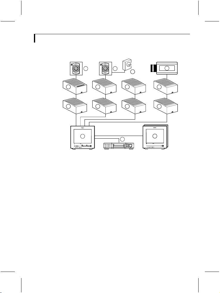
Thank you for buying this accessory for your observation system.
>
N
<
E
R
A
A
R
F
6 6
4
4 4
1
Colour Observation system
_
talkaction menu
+ next
auto
>
N
<
E
R
A
A
R
F
8
4
4
4
2
view
1 System monitor
2 Video recorder (VCR)
3 Slave monitor
4 Accessory boxes (0-2 per cable)
5 Interface box
6 System cameras
7 Non system cameras (CVBS)
8 Mains power adapter
The following items are included in this kit:
1 Interface box
1 System cable (5m/15ft)
1 User manual
Colour Observation Monitor
Colour Observation Monitor
CL 66610005_005a.AI
7
5
4
3
g
4
Page 4

The interface box can be used to add, or extract, normal standard audio
and/or video signals to, or from, your Colour Observation system.
This means that the interface box can be used to connect a third party
camera to your Colour Observation system. It can also be used to
connect e.g. a Cash Register Interface to the Colour Observation system,
or to connect a system camera to a third party system.
Other possible configurations are described in chapter 'Possible
configurations'.
Selection between the twisted pair system cable input and CVBS/Audio
input is done by means of an outside switch.
Installation
Remark: When the systemconfiguration is altered, the system monitor needs to check
and memorise the configuration of the cameras and accessories connected to its inputs.
This is done automatically when the power is switched on. Use the power switchto
switch off; only operating the power save key is not sufficient. If switching off is
impracticable, use the auto install option of the system monitor's install menu.
g
5
Page 5
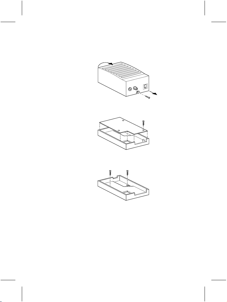
Mounting the box
1 Loosen the screw holding the cover and remove the cover.
CL 76610003_001.AI
2 Remove the circuit board
1.
CL 66610005_502.AI
3 Fasten the bottom plate of the box with two screws.
CL 66610005_504.AI
4 Fit the circuit board.
5 IMPORTANT: Adjust the settings of the circuit board switches to
configure the box according to your system. See section 'settings'.
6 Fit the cover and secure the screw holding it.
7 Now make the connections. See section 'possible configurations' for the
correct connections and the setting of the 'input selector switch' and the
internal 'slide switches'.
g
6
Page 6

System cable
For the interconnections between the monitor, accessories and camera,
a system cable is supplied. For an optimum picture and sound quality,
you should always use 4-wire dual twisted-pair cable when extending the
connection (max. 300m/900ft). The cable and plugs are available in the
hobby and professional trade. Fix the connectors to the cable
corresponding to the figure below.
4
5
4
3
2
5
4
3
2
5
4
3
2
2
3
2-3
4-5
2-3
CL 66610005_006.AI
Caution: The plugs used for the observation system have the same dimensions as
standard telephone plugs.
Never connect the security system with telephone equipment!
External power supply
5
4-5
If the cable length between monitor and system camera exceeds
200m/600ft after an accessory is inserted in the line, a mains power
adapter (optional) should be used to power the system camera
(see accessories). In this way the max. allowed cable length is extended to
300m/900ft.
g
7
Page 7

There are two ways to connect a mains power adaptor to the system;
• To the external supply socket at the rear of the system camera, or
• to the external supply socket (4) at the inside of the interface box.
Remark: This does not apply for the VSS2903/19T.
Location of switches and connectors
1 4 6 7
OUTPUT
24V INT
LAST YES
2
5
3
CABLE LENGTH
COMPENSATION
1 Auxiliary audio out (Cinch)
2 Auxiliary video out (BNC)
3 System cable output (output to connect system monitor)
4 Supply socket for mains power adaptor
5 Cable length compensation selector
6 Slide switches (last in line/power supply internal or external)
7 Volume preset
8 Auxiliary audio in (Cinch)
9 Auxiliary video in (BNC)
10 Input selection switch (Auxiliary/System camera)
11 System cable input (input for system camera)
EXT.
NO
INPUT
8
9
10
11
CL 76610003_002.AI
g
8
Page 8

Settings
Input selection switch (10)
With this switch you can select which audio/video input is displayed on
the screen of the system monitor.
There are two possibilities:
• CAMERA
The system camera input is selected.
When a system camera is connected, the system monitor reproduces the
image and sound from the system camera.
• AUX.
The auxiliary input is selected.
When a third party camera is connected, the system monitor reproduces
the image and sound of the third party camera.
Remark: It is not possible to connect both a device to the aux. input and to the
camera input when the selector switch is in camera position.
Internal switches
Remark: This option does not apply for the VSS2903/19T.
Two switches, located on the circuit board inside the case, are used to
configure the circuit according to the system. The two small slide
switches have the following functions:
Switch Description
24V INT EXT Power supply (24V) Internal/External
LAST YES NO Last in line
g
9
Page 9

Power supply Internal/External (6)
Set this switch to;
• INT
When no external power supply is used.
• EXT
When an external power supply is used.
Last in line switch (6)
Set this switch to;
• YES
When the interface box is the last accessory box in the system cable.
• NO
When another accessory box is connected to the system camera input of
the interface box.
Volume preset (7)
By means of the volume preset, you can adjust the audio level of the
device (for e.g. of a third party camera) which is connected to the 'audio
in'-input.
Cable length compensation selector (5)
This selector adapts the interface box to the length of the system cable
connecting system monitor and interface box. This to optimize the
picture quality. Set the cable length compensation selector to the correct
cable length. The length set must be the same as the length of the system
cable connecting the system monitor and interface box
(0-300m/900ft max.).
Remark: This only compensates for the aux. input.
g
10
Page 10

Possible configurations
This section shows the system configurations which are possible with the
interface box. The figure below shows a block diagram with the
audio/video signal paths.
OUTPUTSINPUTS
>
N
<
E
A
R
R
A
F
VIDEO -IN (BNC)
AUDIO-IN (CINCH)
The following configurations are possible:
Remark: In some configurations,the camera cannot be synchronisedto the system
monitor (not locked). When a quad monitor is used in quadmode, it will result in
unusable pictures.
1 Third party camera, video and audio signals (not locked)
Third party camera
AUX. INPUT
I/F box
AUX. OUTPUT
VIDEO-OUT (BNC)
AUDIO-OUT (CINCH)
A/A box or
int. box
Colour Observation system
_
view
talkaction menu
auto
+ next
CL 76610003_003.AI
Colour Observation system
_
view
talkaction menu
auto
+ next
11
camera aux.
24V
EXT.
INT.
NO
YES
LAST
CL 76610003_007.AI
g
Page 11

2 System camera with external audio (locked)
Remark: Audio from the aux. input isalways added tothe camera sound.
>
N
<
E
A
R
R
A
F
A/A box
A/A box or
int. box
I/F box
Microphone
24V
EXT.
INT.
NO
camera aux.
YES
LAST
3 VCR input and output of separate camera (locked)
>
N
<
E
A
R
R
A
F
camera aux.
A/A box
I/F box
24V
EXT.
INT.
NO
YES
LAST
VCR
only sound of camera
A/A box or
int. box
Colour Observation system
_
view
talkaction menu
auto
+ next
CL 76610003_009.AI
Colour Observation system
_
view
talkaction
menu
auto
+ next
CL 76610003_005.AI
g
12
Page 12

4 Third party monitor (Break-out box)
• with system monitor attached, locked
• without system monitor attached, not locked
>
N
<
E
A
A/A box or
R
R
A
F
int. box
A/A box or
int. box
I/F box
24V
EXT.
INT.
NO
camera aux.
YES
LAST
5 Cash Register Interface (locked, with external audio loop)
>
N
<
E
A
R
R
A
F
camera aux.
A/A box
I/F box
24V
EXT.
INT.
NO
YES
LAST
Cash Register
Interface
Third Party
A/A box or
int. box
Colour Observation system
_
talkaction menu
view
+ next
auto
Third party
CL 76610003_006.AI
Colour Observation system
_
talkaction
menu
view
+ next
auto
CL 76610003_004.AI
13
g
Page 13

6 System camera at long distance (locked)
(max. cable length 200m/600ft)
>
N
<
E
A
R
R
A
F
I/F box
A/A box or
int. box
Colour Observation system
talkaction menu
_
view
+ next
auto
Power supply
NO
camera aux.
24V
EXT.
INT.
YES
LAST
Remark: This option does not apply for the VSS2903/19T.
CL 76610003_008.AI
g
14
Page 14

Technical specifications
TV standard both PAL and NTSC
Power supply through the system cable (24 V
Power consumption 70 mA
System connectors RJ11E modular ("telephone" connectors)
System cable 4-wire dual twisted-pair telephone cable
Inputs
Camera input RJ11E system input
Auxiliary inputs
• audio input Cinch (0.5 V
• video input BNC (1 V
• power input External supply socket, 24 V
(optional)
Outputs
System monitor output RJ11E system output
Auxiliary outputs
• audio output Cinch (0.5 V
camera input
• video output BNC (1 V
camera input
Weight 170 gr.
Dimensions (hxwxd) 119 x 77 x 42 mm
Ambient conditions ammonia resistant
Ambient temperature
• operating -20...+55 °C
• storage -25...+70 °C
Ambient humidity 20...98 %RH
Specifications may change without notice.
, 10 kOhm)
pp
, 75 Ohm)
pp
, 1 kOhm) from system
pp
, 75 Ohm) from system
pp
DC
)
DC
, 0.3 A
147
 Loading...