

Page 1

Electro Magnetic Compatibility (EMC)
This equipment complies with European rules for EMC according to
EN55013, EN55020 and EN50082-1.
Operation is subject to the following two conditions:
1 This device may not cause harmful interference.
2 This device must accept any interference received, including interference
that may cause undesired operation.
The equipment conforms with the EMC directive and low-voltage
directive.
This device complies to FCC rules under test conditions that included
use of system cables and connectors between system components. If you
have any problems, contact your dealer.
Warnings
Any unauthorized modification to this equipment may cause violation of
the FCC rules resulting in the revocation of the authorization to operate
the equipment.
To prevent fire or shock hazard, do not expose this accessory to rain or
moisture.
The exclamation mark within a triangle is intended to alert the
user to the presence of important operating and maintenance
(servicing) instructions in the literature accompanying the
appliance.
2
Page 2

English
Alarm/Action Box
Table of contents
Introduction.................................................................................................................4
Installation....................................................................................................................6
Mounting the box
Installation and setting of an optional
Passive Infra-Red (PIR) detector
Location of the PIR
Installation of the PIR
PIR settings
Walk test LED
Pulse counter
System cable
Action output
Alarm input
Settings..........................................................................................................................13
Designating the box (CAMERA # switch)
Box number
Tamper switch active
Last in line switch
Double addressing error
English
g
Page
Read these instructions, before putting your system in operation
g
3
Page 3
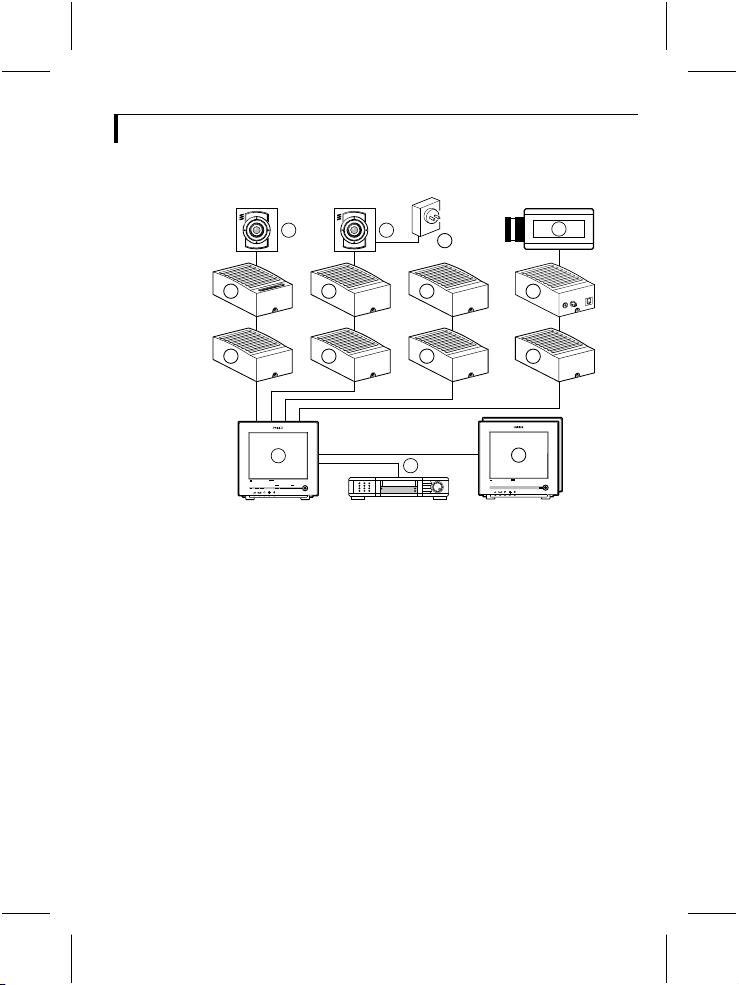
Introduction
Thank you for buying this accessory for your observation system.
>
N
<
E
R
A
A
R
F
6 6
4
4 4
1
Colour Observation system
_
talkaction
menu
+ next
auto
>
N
<
E
R
A
A
R
F
4
8
4
4
view
2
Colour Observation Monitor
Colour Observation Monitor
7
5
4
3
CL 66610005_005b.AI
1 System monitor
2 Video recorder (VCR)
3 Slave monitor
4 Accessory boxes (0-2 per cable)
5 Interface box
6 System cameras
7 Non system cameras (CVBS)
8 Mains power adapter
The following items are included in this kit:
1 Alarm/action box
1 System cable (5m/15ft)
1 User manual
1 PIR unit (for version with PIR)
1 Cable (50 cm) for interconnection between alarm/action box and
PIR (for version with PIR)
g
4
Page 4

N.O. = Normally Open
N.C. = Normally Closed
common
CL 66610005_511.AI
N.O.
N.C.
The alarm/action box performs two distinct functions:
1 Action
This function, for example, opens a door remotely.
Pressing the action button of the system monitor activates a relay contact.
This contact (N.O., N.C.) can activate, for instance, a door opener.
Note that the action button only activates the action box designated to
the camera input whose picture is shown on the monitor screen.
2 Alarm
This function provides alarm inputs to the security system. All kinds of
detectors having a N.O. or N.C. contact are supported, for example:
• infrared detectors
• smoke detectors
• magnetic door/window contacts
When a detector triggers the alarm/action box, the system monitor
automatically switches to the camera input the alarm/action box is
designated to. The system monitor produces an alarm and activates its
alarm contact.
There are two versions of the alarm/action box: one with a Passive
InfraRed (PIR) motion detector and one without. The description in this
manual applies to both versions.
If the automatic camera sequence is active, it stops at the camera input in
question.
g
5
Page 5
Installation
Remark: When the system configuration is altered, the system monitor needs to check
and memorize the configuration of the cameras and accessories connected to its inputs.
This is done automatically when the power is switched on. Use the power switch to
switch off. Operating the power save key is not sufficient.
If switching off is impracticable, use the auto install option of the system monitor's
install menu.
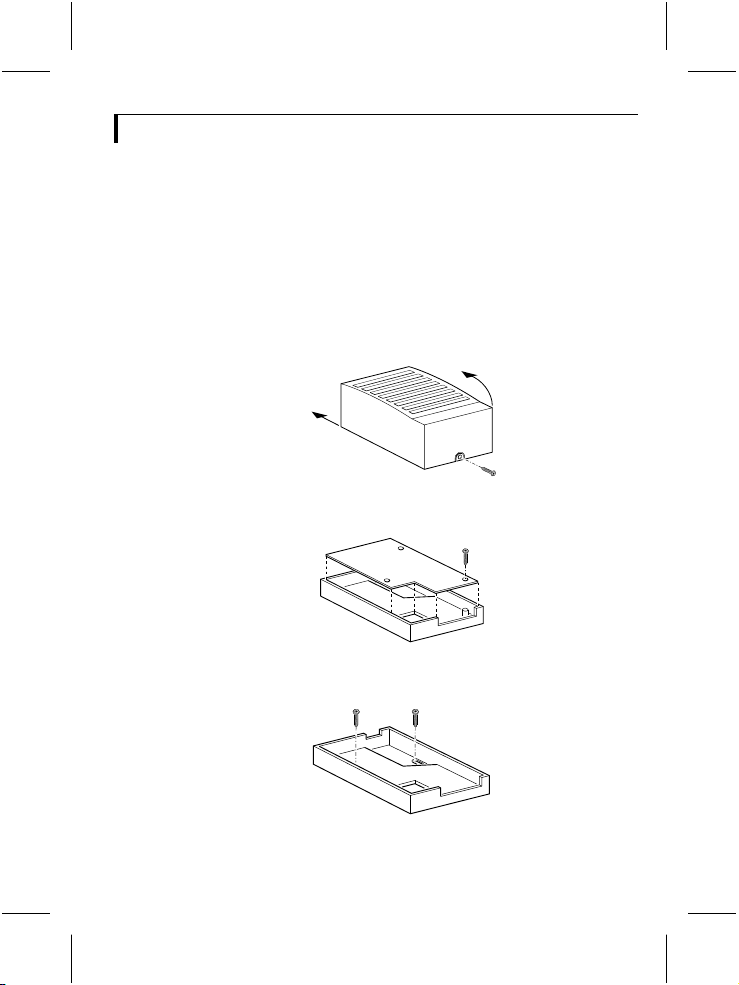
Mounting the box
1 Loosen the screw holding the cover and remove the cover.
CL 66610005_501.AI
2 Remove the circuit board
1.
CL 66610005_502.AI
3 Fasten the bottom plate of the box with two screws.
CL 66610005_504.AI
g
6
Page 6

4 Fit the circuit board.
5 Now make the connections as described in section 'Action output'.
Remark: See section 'Installation and setting of an optional Passive
Infra-Red (PIR) detector',for installationand connection of an PIR-detector.
6 IMPORTANT: Adjust the settings of the circuit board switches to
configure the box according to your system. See section 'settings'.
7 Fit the cover and secure the screw holding it.
Installation and setting of an optional Passive Infra-Red
(PIR) detector
Location of the PIR
The position of the PIR determines its view.
Select a location where an eventual burglar is most likely to be detected.
Place the sensor at a height of ± 2.2 m to accomplish the largest field of
view (see figure below).
Sensor range (lens position 0°)
Side view Top view
O
14M
46Ft
110
CL 76610006_001.AI
2.2M
7.2Ft
4M
13.15Ft
8M
26.3Ft
Be aware of the following before mounting the PIR:
• Avoid a location of the PIR near to radiators, heating/cooling ducts or
air conditioners.
• Do not point the sensor's field of view to windows subject to direct
sunlight or drafts.
• Do not block the sensor's field of view by placing large objects in its line
of sight (e.g. curtains, potted plants, furniture).
g
7
Page 7

Installation of the PIR
1 Remove the fixation-screw (1) and open the housing by releasing the
locking latch (2). Both are located at the bottom of the unit.
3
1
CL 76610006_002.AI
2 Remove the circuit board by loosening the fixation-screw (
2
1).
Warning: Never touch the face of the PYRO sensor (refer to lay out drawing
next page).
3 Knock out the desired mounting holes (1) and wiring holes (2) in the
bottom plate.
1 2
1
CL 76610006_003.AI
4 Thread the wires through the knocked out wiring hole(s).
5 Fasten the bottom plate with two screws, using the mounting holes.
6 Fit the circuit board.
g
8
Page 8

Adjust lens position (0°, -5° or -10°) according to desired maximum
sensor range (see table below).
Remark: Do not use positions +5° or +10° as they do not apply to this PIR.
Sensor height Maximum sensor range (m) / Lens position (°)
0° -5° -10°
2.5 m 14 m 12.5 m 11 m
2.0 m 12 m 10.5 m 9.5 m
1.5 m 10 m 8.5 m 8 m
7 Make the interconnections between the PIR and the alarm/action box
with the cable supplied (see figure below).
2 14 3
+10
+5
-5
-10
0
NC
GND
+12V
NC
_
PIR
+
5 87 6
1 Terminal block (for interconnection with alarm/action box)
2 Lens position (sensor range adjustment)
3 Jumper (walk test LED activated/deactivated)
4 Tamper switch
5 PYRO sensor
6 Jumper (1, 2 or 3 pulse count)
7 Locking latch
8 Terminal block in alarm/action box
g
9
CL 76610006_004.AI
Page 9

8 Adjust settings of walk test LED and/or pulse counter, if required.
See section 'PIR settings'.
9 Fit the front cover. Check if it is locked to the bottom side.
10 Fasten the fixation-screw.
Remark: The PIR detector will start detecting movement approximately 2 minutes
after mains power-on.
PIR settings
There are 2 jumpers to set the PIR to your own requirements:
• Walk test LED
• Pulse counter (1, 2 or 3)
See previous figure for the location of the jumpers.
Walk test LED
• jumper installed:
Walk test LED is activated. When the PIR sensor is triggered, the LED
will light.
• jumper not installed:
Walk test LED is deactivated.
Pulse counter
Set this jumper to select the number of times the sensor must be triggered
(1, 2 or 3 times) before an alarm is generated.
The following jumper settings are possible:
2X 3X1X
3P
3P
3P
2P
2P
2P
CL 76610006_005.AI
Remark: The PIR detector is equipedwith a'detection window'. In case of an
alarm,15 seconds after the last movement has been detected,a new alarm can be
generated.
g
10
Page 10

System cable
For the interconnections between the monitor, accessories and camera a
system cable is supplied. For optimum picture and sound quality you
should always use 4-wire dual twisted-pair cable when extending the
connection (max. 300m/900ft). The cable and plugs are available in the
hobby and professional trade. Pay attention that the connectors are fixed
to the cable corresponding to the figure below.
5
4
5
4
3
2
5
4
3
2
5
4
3
2
4-5
2-3
If the cable length between monitor and camera exeeds 200m/600ft after
an accessory is inserted in the line a mains power adapter should be used
to power the camera (see accessories).
Caution: The plugs used for the observation system have the same dimensions as
standard telephone plugs.
Never connect the security system with telephone equipment!
3
2
2-3
CL 66610005_006.AI
4-5
The two sockets for the system cable are interchangeable. One socket
connects the box to the system component previous in the cable, the
other to the next (if any).
g
11
Page 11

Action output
The figure below shows the screw terminals to which, for example, a
door-opener circuit can be connected.
21 3
CAMERA #
5
6
4
7
23
NC
_
PIR
+
1
0
9
8
OFF
Y
2
123
1 BOX
TAMPER
N LAST
ON OFF
6
45
1 System-cable input
2 System-cable output
3 Switches 1, 2 & 3
4 Rotary switch (designates the box to a camera input)
5 Tamper switch
6 Terminal block for optional Passive Infra-Red detector
g
CL 66610005_505.AI
12
Page 12

Alarm input
The alarm/action box provides inputs for detectors with N.O. and N.C.
contacts. The figure above shows how they are connected to the screw
terminals of the box.
Note: - When no detectors with N.C. contacts are used terminals 1 and 2 must be
interconnected with a wire.
- When no PIR detector is used terminals NC and –of terminal block (6)
must be interconnected with a wire.
Settings
Four switches - located inside the case, on the circuit board - are used to
configure the circuit according to the system.
• The rotary switch designates the box to a particular camera input.
• The three small slide switches have the following functions:
Switch Off On Description
1 BOX 1 2 number of accessories
2 TAMPER TAMPER OFF tamper-switch override
3 LAST N Y last accessory box
Designating the box (CAMERA # switch)
Designating a box to a camera input means that system monitor
associates the box with a certain camera input (the designated input)
although it is physically connected to another. This causes the system
monitor to switch to the camera connected to that input when for
example an alarm is triggered or the doorbell button pressed. This gives
you the opportunity to use the shortest route when wiring a box.
The figure below shows for example a two camera system with three
accessory boxes. The switches CAMERA # are set according to the camera
(input) to which the boxes are designated.
13
g
Page 13

1
Colour Observation system
talkaction menu
1
2
_
view
+ next
auto
CAMERA #
768
9
5
401
23
CAMERA #
768
9
5
401
23
>
N
<
E
A
R
R
A
F
2
CAMERA #
768
9
5
401
23
>
N
<
E
A
R
R
A
F
CL 66610005_510b.AI
Note: Switch positions 0 and those beyond the maximum number of inputs have no
function.
When two alarm/action boxes are addressed to the same camera input,
both boxes will activate the action relay when the action button on the
system monitor is pressed.
Remark: The maximum amountof accessories on one camera input is two intercom
boxes and two alarm/action boxes.
g
14
Page 14

Box number
This switch (BOX) informs the circuit about the accessory number when
two boxes are designated to the same camera input of the system
monitor. A maximum of two alarm/action boxes can be designated to
one camera input.
Switch 1 (BOX)
position description
1 first box which is designated to the camera input set
2 second box which is designated to the camera input
by CAMERA #
set by CAMERA #
Tamper switch active
On the circuit board a tamper switch secures the box. When opening the
box this switch triggers an alarm on the monitor. To suppress a
continuous alarm message while servicing the system, the tamper-switch
override is set in the OFF position.
Caution: Don't forget to reactivate the tamper switch by switchingthe overrideto
the TAMPER position!
Last in line switch
Set this switch to Y(es) if this alarm/action box is the last accessory box
in the system cable (seen from the system monitor).
15
g
Page 15

Double addressing error
Two alarm/action boxes or intercom boxes, which are designated to the
same camera input, have the same 'box-number'.
Remark: Although the cameras will work, none of the accessories in any cameraline
will be functioning.
If the system monitor detects two boxes with the same designation and
box number, it shows the following error message:
DOUBLE ADDRESSING
“Accessory name”
INPUT X/X
Change from one alarm/action box the BOX switch or the CAMERA #
switch.
Explanation:
INPUT X/X
the physical camera input numbers to
which the double addressed boxes are
connected.
g
16
Page 16

Technical specifications
Power supply through the system cable (24VDC)
Contact ratings action relay 30V, 5A AC/DC
Alarm input trigger threshold > 150Ω (N.C. input)
System connectors RJ11E modular ('telephone' connectors)
System cable 4-wire dual twisted-pair telephone cable
PIR angle of sight
• horizontal 110°
• vertical 20°
Dimensions
• without PIR 119 x 77 x 40 mm
Ambient conditions ammonia resistant
Temperature
• operating +10...+45°C
• storage -25...+70°C
Humidity
• operating 20...90%RH
• storage 20...99%RH
Specifications may change without notice.
< 150Ω (N.O. input)
171
 Loading...