

Page 1

Electro Magnetic Compatibility (EMC)
This equipment complies with European rules for EMC according to
EN55013, EN55020 and EN50082-1.
Operation is subject to the following two conditions:
1 This device may not cause harmful interference.
2 This device must accept any interference received, including interference
that may cause undesired operation.
The equipment conforms with the EMC directive and low-voltage
directive.
This device complies to FCC rules under test conditions that included
use of system cables and connectors between system components. If you
have any problems, contact your dealer.
Warnings
Any unauthorized modification to this equipment may cause violation of
the FCC rules resulting in the revocation of the authorization to operate
the equipment.
To prevent fire or shock hazard, do not expose this accessory to rain or
moisture.
The exclamation mark within a triangle is intended to alert the
user to the presence of important operating and maintenance
(servicing) instructions in the literature accompanying the
appliance.
2
Page 2

English
Intercom Box
Table of contents
Introduction.................................................................................................................4
Installation....................................................................................................................5
Mounting the box
System cable
Doorbell output
External power supply
Volume of the loudspeaker
Settings.............................................................................................................................9
Designating the box (CAMERA # switch)
Box number
Tamper switch active
Double addressing error
Operation...................................................................................................................11
English
g
Page
Read these instructions, before putting your system in operation.
g
3
Page 3
Introduction
Thank you for buying this accessory for your observation system.
>
N
<
E
R
A
A
R
F
6 6
4
4 4
1
Colour Observation system
_
talkaction menu
+ next
auto
>
N
<
E
R
A
A
R
F
8
4
4
4
2
view
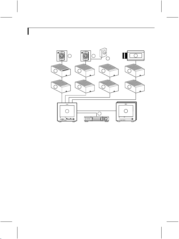
1 System monitor
2 Video recorder (VCR)
3 Slave monitor
4 Accessory boxes (0-2 per cable)
5 Interface box
6 System cameras
7 Non system camera’s (CVBS)
8 Mains power adapter
The following items are included in this kit:
1 Intercom box
1 System cable (5m/15ft)
1 User manual
Colour Observation Monitor
Colour Observation Monitor
CL 66610005_005a.AI
7
5
4
3
g
4
Page 4

N.O. = Normally Open
N.C. = Normally Closed
common
CL 66610005_511.AI
N.O.
N.C.
The intercom box has a doorbell function. This means that a buzzer
inside the system monitor sounds when someone presses the intercom’s
doorbell button. When the doorbell button is pressed the monitor
switches to the camera input the intercom box is designated to. The
intercom box then allows you and the person near the intercom box to
talk to one another.
Installation
Remark: When the system configuration is altered, the system monitorneeds to check
and memorise the configuration of the cameras and accessories connected to its inputs.
This is done automatically when the power is switched on. Use the power switchto
switch off, only operating the power save key is not sufficient. If switching off is
impracticable, use the auto install option of the system monitor’s install menu.
g
5
Page 5

Mounting the box
1 Loosen the screw holding the cover and remove the cover.
CL 66610005_509.AI
2 Remove the circuit board
1.
CL 66610005_502.AI
3 Fasten the bottom plate of the box with two screws.
CL 66610005_504.AI
4 Fit the circuit board.
5 Now make the connections as described below.
6 IMPORTANT: Adjust the settings of the circuit board switches to
configure the box according to your system. See section ‘settings‘.
7 Fit the cover and secure the screw holding it.
g
6
Page 6

System cable
For the interconnections between the monitor, accessories and camera a
system cable is supplied. For an optimum picture and sound quality you
should always use 4-wire dual twisted-pair cable when extending the
connection (max. 300m/900ft). The cable and plugs are available in the
hobby and professional trade. Pay attention that the connectors are fixed
to the cable corresponding to the figure below.
5
4
5
4
3
2
5
4
3
2
5
4
3
2
4-5
2-3
If the cable length between monitor and camera exeeds 200m/600ft after
an accessory is inserted in the line a mains power adapter should be used
to power the camera (see accessories).
Caution: The plugs used for the observation system have the same dimensions as
standard telephone plugs.
Never connect the security system with telephone equipment!
3
2
2-3
CL 66610005_006.AI
4-5
The two sockets for the system cable are interchangeable. One socket
connects the box to the system component previous in the cable, the
other to the next (if any).
g
7
Page 7

Doorbell output
The figure below shows the screw terminals to which a separate bell can
be connected.
12
2
7
123
+24VDC
BELL
BELL
+24V
4
GND
CAMERA #
4
23
1
5
1 BOX
5
6
7
8
9
0
CL 66610005_508.AI
6
4
1 System-cable input
2 System-cable output
3 Switches 1, 2 & 3
4 Rotary switch (designates the box to a camera input)
5 Tamper switch
6 Volume preset
External power supply
If at maximum volume setting the loudspeaker volume remains low, then
connect an external power supply (24V
above (7). This is advised when the intercom box is connected to the
system monitor through a long cable.
, 0,5A), as shown in the figure
DC
3
ON
Y
TAMPER
N LAST
ON OFF
g
8
Page 8

Volume of the loudspeaker
Adjust the volume of the sound reproduced at the intercom box with the
volume preset (6).
Settings
Four switches - located inside the case, on the circuit board - are used to
configure the circuit according to the system.
• The rotary switch designates the box to a particular camera input.
• The three small slide switches have the following functions:
Switch Off On Description
1 BOX 1 2 box number
2 TAMPER OFF ON tamper-switch override
3 LAST N Y last accessory box
Designating the box (CAMERA # switch)
Designating a box to a camera input means that system monitor
associates the box with a certain camera input (the designated input)
although it is physically connected to another. This causes the system
monitor to switch to the camera connected to that input when for
example an alarm is triggered or the doorbell button pressed. This gives
you the opportunity to use the shortest route when wiring a box. The
figure below shows for example a two camera system with three accessory
boxes. The switch CAMERA # is set according to the camera (input) to
which the boxes are designated.
g
9
Page 9

Colour Observation system
talkaction
CAMERA #
1
2
_
menu
view
auto
+ next
768
9
5
401
23
CAMERA #
768
5
401
23
>
N
<
E
A
R
R
A
9
F
1
CAMERA #
768
5
401
23
9
>
<
R
A
F
CL 66610005_510a.AI
Note: Switch positions 0 and those beyond the maximum number of inputs have no
function.
Box number
2
This switch (BOX) informs the circuit about the accessory number when
two boxes are designated to the same camera input of the system
monitor. A maximum of two intercom boxes can be designated to one
camera input.
Switch 1 (BOX)
Position Description
1 first box which is designated to the camera input set
2 second box which is designated to the camera input
by CAMERA #
set by CAMERA #
Tamper switch active
On the circuit board a tamper switch secures the box. When opening the
box this switch triggers an alarm on the monitor. To suppress a
continuous alarm message while servicing the system, the tamper-switch
override is set in the TAMPER OFF position.
Caution: Don’tforgettoreactivate thetamperswitchbyswitchingtheoverrideto
the TAMPER ON position!
Double addressing error
N
E
A
R
g
10
Page 10

Two alarm/action boxes or intercom boxes, which are designated to the
same camera input, have the same ‘box-number’.
If the system monitor detects two boxes with the same designation and
box number, it shows the following error message:
DOUBLE ADDRESSING
“Accessory name”
INPUT X/X
Change from one intercom box the BOX switch or the CAMERA #
switch.
Explanation:
INPUT X/X
the physical camera input numbers to
which the double addressed boxes are
connected.
Operation
The button on the intercom is used as (door)bell. When pushed, the
buzzer in the monitor (system & slave) sounds. The monitor (system &
slave) switches to the camera input the intercom is designated to. The
automatic camera sequence stops. If you don’t react within 3 minutes - by
pushing any button - then the monitor returns to its previous status (for
example, the automatic camera sequence continues).
The system monitor reproduces the sound received from the intercom
box (plus that of the camera the system switched to, if its microphone is
not switched off). To talk back to your visitor push H. The sound
received by the system monitor’s microphone is then reproduced by the
intercom.
g
11
Page 11

Technical specifications
Power supply through the system cable (24VDC)
External power supply
(optional) 24V
Power consumption 0.5W
Contact ratings doorbell
relay 30V, 1A AC/DC
System connectors RJ11E modular
System cable 4-wire dual twisted-pair telephone cable
Dimensions 119 x 77 x 40mm
Ambient conditions ammonia resistant
• temperature operating: +10...+45°C
• humidity operating: 20...90%RH
Specifications may change without notice.
, 0,5A
DC
(“telephone” connectors)
storage: -25...+70°C
storage: 20...99%RH
111
 Loading...