

Page 1
Important notes for users in the U.K.
Warning: to prevent fire or shock hazard, do not expose
camera or monitor to rain or moisture.
The lightning flash with arrowhead
symbol, within a triangle, is intended to
alert the user to the presence of
uninsulated “dangerous voltage” within
the product’s enclosure; that may be of
sufficient magnitude to constitute a risk
of electric shock to persons.
Caution: to reduce the risk of electric shock, do not remove
cover (or back). No user serviceable parts inside. Refer servicing
to qualified service personnel.
The exclamation mark within a triangle is
intended to alert the user to the presence
of important operating and maintenance
(servicing) instructions in the literature
accompanying the appliance.
If the fitted plug is not suitable for your mains socket,
it should be removed and be replaced by an appropriate
plug.
How to replace a plug
• Cut the mains plug from the lead.
• Strip the sheathing so the wires will become free for
the necessary length to connect the UK-mains plug (not
supplied).
The wires in the mains lead are coloured according to
the following code: blue=neutral (N), brown=live (L).
As these colours may not correspond with the colour
markings identifying the terminals in your plug, proceed
as follows:
• Connect the blue wire to the terminal marked N or
coloured black.
• Connect the brown wire to the terminal marked L or
coloured red.
Caution
Do not connect either wire to the earth terminal in the
plug, marked E (or ) or coloured green (or green and
yellow).
Before replacing the plug cover, make certain that the
cord grip is clamped over the sheath of the lead, not
simply over the two wires.
Electro Magnetic Compatibility
(EMC)
This equipment complies with the European rules for
EMC according to EN55013, EN55020 and EN50082-1.
The equipment conforms with the EMC directive and
low-voltage directive.
This device complies with EMC rules under test
conditions that included use of system cables and
connectors between system components. If you have any
problems, contact your dealer.
Warning
Any unauthorized modification to this equipment may cause
violation of the EMC rules resulting in the revocation of the
authorization to operate the equipment.
Note: we advise you to use the following types of mains
power adapters in combination with the camera:
U.K. Philips VCM1162/01R
EUR Philips VCM1162/00R
Fuse
If the mains plug (or adapter) contains a fuse, the value
of this fuse should be 3 Amp. Alternatively, if another
type of plug (not fused) is used, the fuse at the
distribution board should not be greater than 5 Amp.
1
Page 2
Colour Observation Quad
English
Table of contents
Introduction...............................................................................................3
Connection and operation facilities......................................4
Installation..................................................................................................5
Camera
Monitor
Operation of the monitor..............................................................5
Power on/off
Power save/active
Talk function
Action function
Freeze image
View modes
Camera selection
System reset
How do the menus work?...............................................................7
Menu control buttons
The menus...................................................................................................7
Main menu
Camera configuration
Alarm function on/off
Silent function on/off
Alarm history list
Camera dwell time
Auxiliary output selection
Install menu
Display time and date
Time adjustment
Date adjustment
Auto install
Language selection
Alarm function.........................................................................................9
Trouble shooting.................................................................................10
Double addressing
No valid camera input selection
System error
What to do in case of a system error?
Special alarm
System cable ..........................................................................................11
Accessories...............................................................................................11
Tips for maintenance......................................................................12
Englishg
Page
Introduction
Thank you for buying our observation system. By
purchasing this system you possess a sophisticated,
easy-to-operate observation and security system.
It features a Quad mode, in which you can see the
images of up to 4 cameras in 4 quadrants on the
monitor screen.
Operation and programming of the system is performed
through On Screen Display (OSD) menus. With these
menus you can adapt the system to your own
convenience.
If you follow the installation and operation instructions
as described in the following sections, you will quickly
learn how to adjust and operate your observation system.
The following items are included in this kit:
1 Monitor
1 Camera + camera wall bracket
1 System cable (25m/75ft)
1 System manual + 1 camera manual
Accessories:
The system can be extended by one or more system
accessories or other peripheral equipment, such as:
• Intercom box
• Alarm/Action box
• Alarm/Action box + PIR motion detector
• Cameras (to a maximum of 4)
• Interface box
• Slave monitor (to a maximum of 3)
• Mains power adapter
• (Time lapse) Video Recorder (VCR)
>
N
<
E
R
A
A
R
F
6 6
4
4 4
1
Colour Observation system
_
talkaction menu
view
+ next
auto
>
N
<
E
R
A
A
R
F
4
8
4
4
2
3
Colour Observation Monitor
Colour Observation Monitor
CL 66610005_005a.AI
5
4
7
Read these instructions, before putting your system in
operation.
3
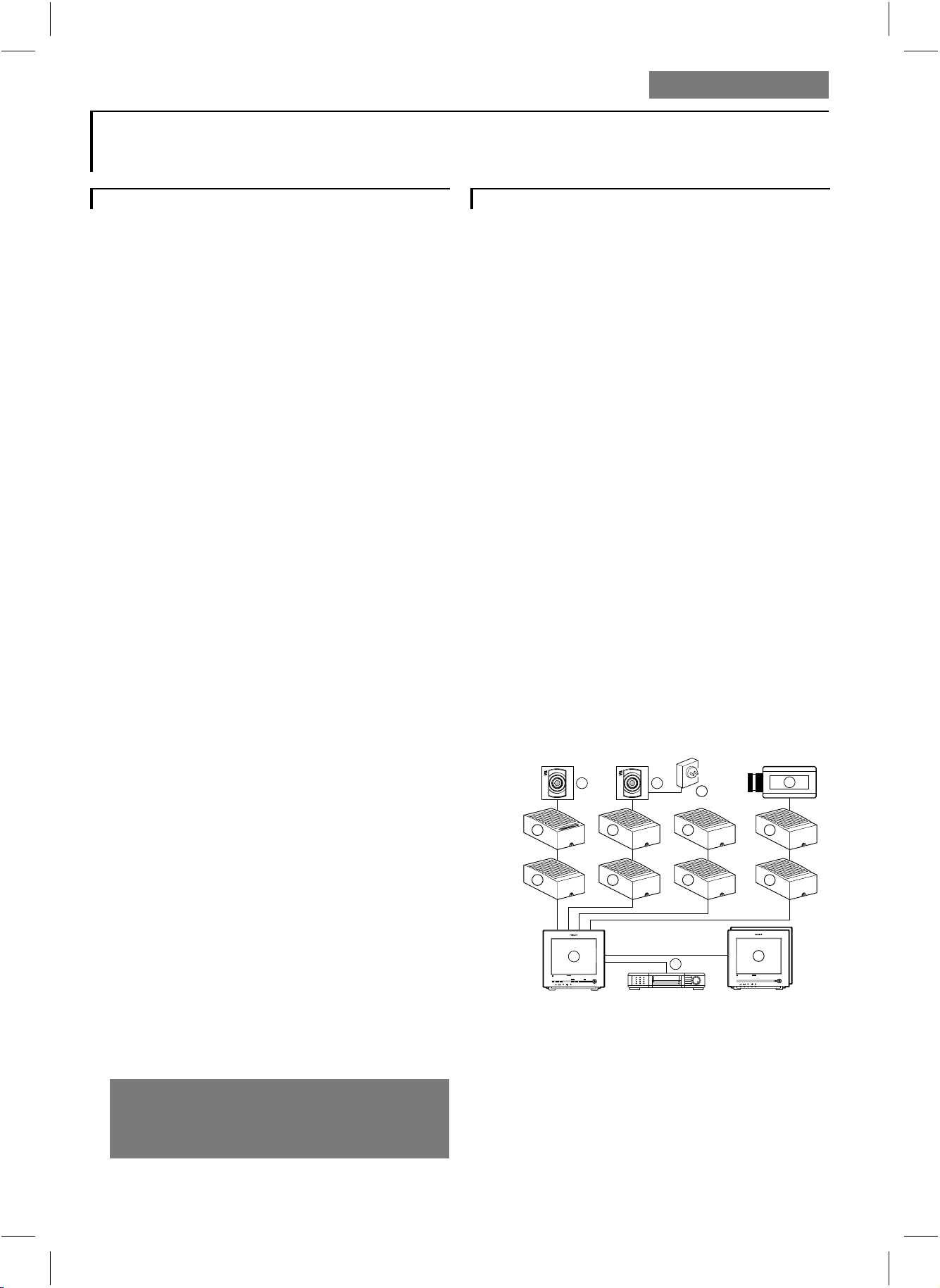
1 Quad monitor 5 Interface box
2 Video recorder (VCR) 6 System cameras
3 Slave monitor(s) 7 Non system cameras (CVBS)
4 Accessory boxes 8 Mains power adapter
(0-2 per cable)
g
Page 3
Mains supply:
The monitor accepts a mains power voltage of
100-240V~, 50/60Hz.
For the camera(s) and system accessory boxes a safe
low-voltage (16-32V _) is supplied by the Quad monitor
through the system cable.
The Quad monitor, camera(s) and accessories are
automatically switched on when the Quad monitor is
switched on with the rear mains switch.
Connection and operation facilities
Up L
6
There are two possibilities:
Menu off
• In full screen mode this button selects the next camera
input (video image + sound)
• In Quad mode this button selects the next camera input
indicated by a green border. The selected camera input
will be used for sound and for the talk and action
buttons.
Menu on
• This button decreases or changes the value of a selected
menu item.
Freeze/next O
7
There are two possibilities:
Menu off
This button freezes or unfreezes the selected camera
image in full screen mode or in quad mode
(green border)
Menu on
This button selects the next menu item
View J
8
Press this button to select the different view modes.
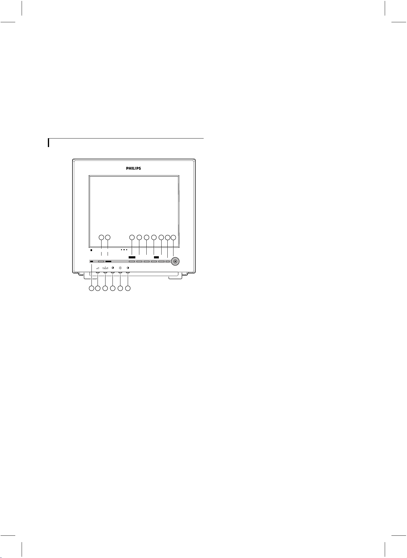
23 4 5 6 7 8
Colour Observation Quad
talk action
1
11 12 13 14 15
menu
_
+ next
freeze
910
view
CL 66610005_102.AI
1 Microphone
2 Talk H
While you press this button, you can speak through the
optional intercom (release the button to listen).
Action I
3
By means of this button you can with an optional
Alarm/Action box, for instance, open a door.
Menu M
4
On Screen Display menu on/off.
Remark: If no button entry is given within 30 seconds the
menu will automatically switch off.
Down K
5
There are two possibilities:
Menu off
• In full screen mode this button selects the previous
camera input (video image + sound)
• In Quad mode this button selects the previous camera
input indicated by a green border. The selected camera
input will be used for sound and for the talk and action
buttons.
Menu on
• This button decreases or changes the value of a selected
menu item.
The following view modes can be selected:
• Full screen mode
• Camera sequence mode
• Quad mode
• VCR mode
System mode indication LED
9
The following modes are possible:
• Power on (LED is green)
• Power save mode (LED is red)
• Silent mode (LED is amber)
• Alarm during power silent mode (LED is red blinking)
Power save/active
10
P
Image and audio of the monitor off/on.
Volume
11
Q
Volume control for the sound of the camera or intercom
box (optional).
Hue
12
q
Hue control
Remark: For the European version this control has no function.
Colour
13
S
Colour intensity control
Remark: The colour intensity control will also affect the
colour intensity of an attached slave monitor and an attached
VCR.
Brightness
14
(
Brightness control
Contrast
15
T
Contrast control
g
4
Page 4
slave
out
power
gnd
CL 66610005_003.AI
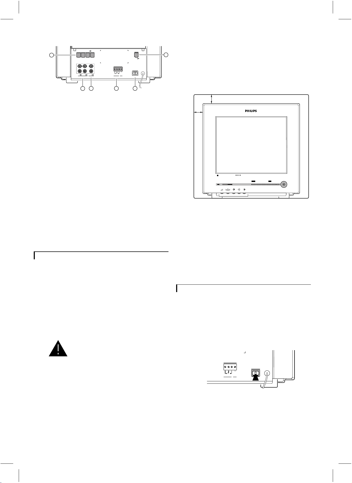
16
1234
video
audio
in
camera in
max 24V 2A
out
out
aux
VCR
18 20 21
17
out
alarm
16 Camera inputs (1 to 4)
17 VCR in/output
The VCR output contains the image (full/quad)
displayed on screen (no menu) and the sound of the
selected camera input.
Aux. output
18
Output which contains the image and sound of one of
the 4 camera inputs (menu controlled).
Slave output
19
Output for an optional slave monitor, showing the
image and sound of the selected camera image.
Alarm output contact (N.O./N.C.)
20
In case of an alarm this potential free contact (Normally
Open/Normally Closed; 24V/2A max.) can activate a
video recorder, siren or telephone selector.
Mains power switch
21
Observation system on/off.
Installation
Before you start to use the observation system, the Quad
monitor, camera(s) and optional accessories should be
installed. In this chapter the installation of the Quad
monitor and a camera is described. For more detailed
information about the installation and operation of a
camera and accessories you should consult their manuals.
Remark: When the Quad monitor is switched on by means
of the rear power switch, the monitor scans all camera inputs
(= system check). This to check and register which cameras and
accessories are connected to the camera inputs (= camera
configuration).
When the configuration is altered, the
system must be scanned again. Therefore
always switch off the system when a
camera or accessory is added or removed.
Only operating the power save button is
not sufficient.
Camera
To ease the installation of the camera, take it and the
Quad monitor to the area you want to observe. With the
monitor on site you can check whether the camera
covers the required area.
For the installation of the camera you should consult the
camera manual.
Monitor
19
When you have installed the camera(s) the monitor can
be installed.
1 Place the monitor on a solid base (leave at least 3 cm
around each side of the monitor for ventilation).
3 cm
3 cm
Colour Observation Quad
talk action menu_+
view
next
freeze
CL 66610005_110.AI
2 Connect the camera(s) and (optional) devices to the
monitor.
3 Connect the monitor to the mains supply.
4 Switch on the main power switch (21) and wait until the
camera image appears.
5 If necessary you can optimise the camera image by
means of the contrastT, brightness(and/or colour
control buttons at the front of the monitor.
S
Operation of the monitor
When you have installed the camera(s), the monitor and
the accessories, you can start to work with your
observation system.
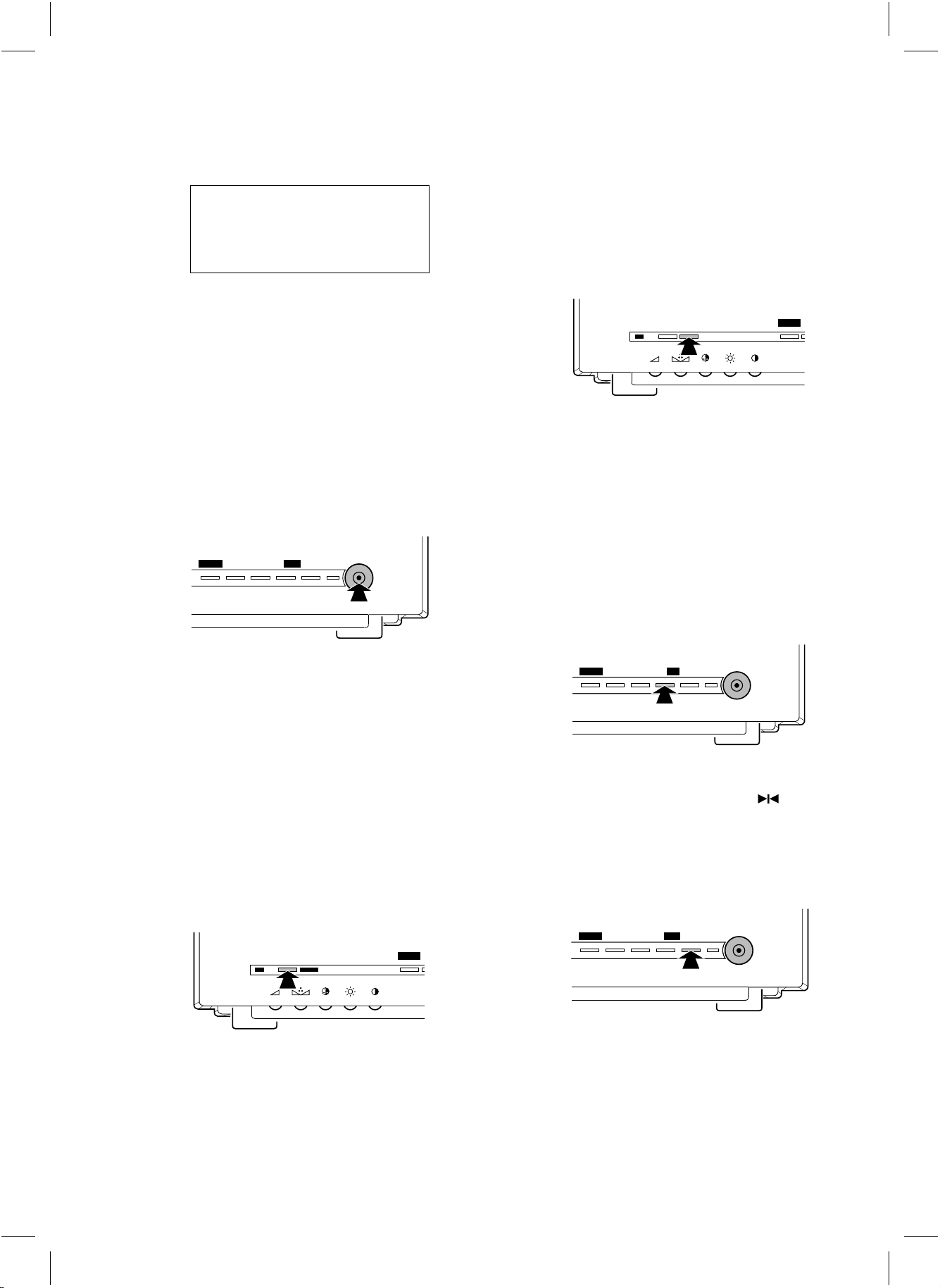
Power on/off
Push button at the rear of the monitor.
max 24V 2A
out
alarm
gnd
power
CL 66610005_011.AI
g
5
Page 5
1 Power on
The monitor switches ON.
The following text appears on the monitor screen:
PHILIPS
OBSERVATION SYSTEM
VERSION x.x
Doorbell function:
If the doorbell button on the intercom box is pressed a
buzzer sounds and the symbol u is visible at the upper
left-hand side of the monitor screen (full screen mode) or
of the camera quadrant (Quad mode). The monitor selects the camera input the intercom box is designated to.
Remark: The talk button and doorbell function are only
functional in combination with an intercom box (optional).
SYSTEM CHECK
(x.x = version number)
After approximately 30 seconds or when a button is
pressed the camera image appears on the monitor screen.
Remark: At the first installation or when one or more cameras
or accessories were added or removed from the system, the text
CONFIGURATION CHANGED will appear on the monitor
screen. In this way the monitor indicates that it has stored the
new system configuration.
2 Power off
The monitor switches OFF (system mode indication
LED is off).
Power save/active
_
menu
+ next
1 Power active
Image and sound of the monitor are switched on (power
indication LED is green)
freeze
view
CL 66610005_112.AI
Action function
talk action menu
CL 66610005_016.AI
Press I, for instance to open a door. As long as
I is pressed, a buzzer sounds and the symbol
is visible at the upper left-hand side of the monitor
screen (full screen mode) or of the camera quadrant
(Quad mode).
If the system consists of more cameras, the action is
done in the action box designated to the selected camera
input.
Remark: The action button is only functional in combination
with an Alarm/Action box (optional).
Freeze image
menu
_
nextfreeze
+
view
U
2 Power save
Image and sound of the monitor are switched off. The
camera continues to transmit images and sound to the
VCR, slave and aux. output. The alarm functions also
remain active.
In power save mode you can select between two
functions (selection is menu controlled):
• non-silent function (system mode indication LED is red)
• silent function (system mode indication LED is amber)
Talk function
talk action menu
CL 66610005_015.AI
Press H to speak through the intercom (optional).
Release the button to allow your visitor to speak to you.
Remark: In Quad mode, the intercom box for the selected
camera (green border) will be used.
CL 66610005_117.AI
With this button you can freeze the selected image.
A frozen image can be recognized by the symbol.
The freeze function can be used in all view modes, when
no menu is displayed. Press J, L,
K or Oagain to obtain a live image again.
View modes
_
menu
+ next
The following view modes can be selected:
1 Full screen mode
The monitor displays the image (and sound) of one of
the connected cameras.
freeze
view
CL 66610005_118.AI
g
6
Page 6

The selected camera input number is visible at the upper
left-hand corner of the monitor screen. Press K
or L to select the previous or next camera input.
2 Camera sequence mode
The monitor switches slowly between the pictures (image
+ sound) of the connected cameras. The camera input
number and the symbolVare visible at the top of the
screen.
Remark: This mode is only functional when the observation
system has more than one camera.
3 Quad mode
The images of the (max.) 4 connected cameras are
displayed simultaeously at ¼ of the screen size. The
sound is coming from the selected camera whose border
is high-lighted in green. Unavailable images are shown as
grey areas. By pressing Lor Kyou can
select the previous or next camera input.
How do the menus work ?
With the On Screen Display menus you can adjust
various system control functions.
The following menus can be selected:
HISTORY
16:35:59
01:11:32
04:23:45
23:59:12
13:15:00
03:02:27
INSTALL MENU
CAMERA
ALARM
SILENT
HISTORY
DWELL TIME
AUX.
INSTALL
MAIN MENU
: 1 2 _ 4
: Y N _ Y
: ON
:
: 15 S
: 1
:
94-12-23
95-02-22
96-05-06
96-06-02
96-08-18
96-08-30
DISPLAY
TIME
DATE
AUTO INSTALL
LANGUAGE
POWER
ALARM1
CUT1
SHORT4
FAIL1
TAMP2
LEFT
13:12:46
96-09-19
ENGLISH
CL 66610005_021g.AI
4 VCR input
The monitor reproduces the image and sound of the
VCR. The symbolWis visible at the left-hand top side
of the monitor screen.
Camera selection
_
menu
+ next
freeze
view
CL 66610005_119.AI
Press K or L to select the previous or
next camera input.
System reset
By pressing K and L simultaneously for
at least three seconds while switching on the main power
switch at the rear of the Quad monitor, you can set the
Quad monitor to the factory default settings. During a
reset a beep sounds and the following text is shown on
the monitor screen:
OBSERVATION SYSTEM
After approximately 30 seconds or when a button is pressed the message will disappear from the monitor screen.
Remark: After a system reset all system configuration settings
are lost. Use the AUTO INSTALL function (see Installation
Menu) to scan the system. The Quad monitor will register the
camera configuration again.
PHILIPS
VERSION x.x
SYSTEM RESET
The menu control buttons
The menus are operated with the following control
buttons:
1 M
• Switches the main menu on/off
Remark: If no button entry is given within 30 seconds the on
screen display menu is automatically switched off.
• Selects the previous menu when a sub-menu is selected.
2 O
• Selects the next menu item.
3 K/L
• Decreases, increases or changes the value of a selected
menu item.
• Selects the next menu if the symbol
is highlighted.
Y
The Menus
Main Menu (MAIN MENU)
The items of the Main Menu are discussed in the
following sections:
Camera configuration (CAMERA)
1
By means of camera configuration you can see which
camera inputs (1 to 4) are in use.
• Switch on the Main Menu.
r
next to the text ‘CAMERA’ the numbers of the camera
inputs to which a camera is connected are displayed.
CAMERA : 1 2 - 4
g
7
Page 7

2 Alarm function active yes/no (ALARM)
With this function you can activate or deactivate the
alarm function of the connected camera inputs.
• Y
The alarm function of this camera input is activated.
• N
The alarm function of this camera input is not activated.
In case an alarm box triggers an alarm, the buzzer, the
alarm relay and the slave alarm information are not
activated. The history list is not updated with the alarm
event. Special alarms will always remain enabled.
Select ALARM from the Main Menu;
• Press O until the camera input of which you
want to activate or deactivate is highlighted.
ALARM :■Y N-N
↓
ALARM : Y
N -N
■
↓
•Press K or L to deactivate or activate the
alarm function of the selected camera input.
↓
ALARM : Y
3
Silent function on/off (SILENT)
Y -N
■
The silent function can be used when the monitor is in
‘power save’ mode.
• Silent function OFF
In case of an alarm the monitor automatically switches
to ‘active’ mode. The monitor reproduces the image and
sound of the camera input the Alarm/Action box
(which triggered the alarm) is designated to.
• Silent function ON
On occurrence of an alarm the monitor stays in ‘power
save’ mode. No image or sound is reproduced, the
system mode indication LED is red blinking. The alarm
output contact is activated, information is sent to the
slave monitor and the history table is updated with this
alarm event.
Remark: The camera image and sound will always be sent to
the VCR output and slave output.
Select SILENT from the Main Menu;
• Press O until the text next to SILENT is
highlighted.
• Press K or L to deactivate (OFF) or
activate (ON) the silent function.
4
Alarm history list (HISTORY)
When you select HISTORY a list with the date, time,
kind of alarm and the camera input number of the last 9
alarm events is displayed.
HISTORY
94-12-23
95-02-22
96-05-06
96-06-02
96-08-18
96-08-30
16:35:59
01:11:32
04:23:45
23:59:12
13:15:00
03:02:27
POWER
ALARM1
CUT1
SHORT4
FAIL1
TAMP2
CL 66610005_023g.AI
Select HISTORY from the Main Menu;
• Press O until the symbol
next to HISTORY is
Y
highlighted.
• Press K or L.
r
The history list appears.
• Press M when you want to return to the Main
Menu.
Remark: The explanation of the fault indications can be found
in the section ‘Special alarms’.
Camera dwell time (DWELL TIME)
5
With this option you can change the switching time
interval (1 to 30 seconds).
Remark: This mode is only functional when you have enlarged
the system to at least 2 cameras.
Select DWELL TIME from the Main Menu;
• Press O until the actual dwell time is highlighted.
• Press K or L to decrease or increase the
dwell time.
Auxiliary output selection (AUX.)
6
With this option you select which camera’s output signal
is sent to the aux. output.
Select AUX. from the Main Menu;
• Press O until the present selected camera input
number next to AUX. is highlighted.
• Press K or L to select the previous or
next camera input number.
Install menu (INSTALL MENU)
Select INSTALL from the Main Menu;
• Press O until the symbol
highlighted.
• Press K or L.
r
The Install Menu appears.
• Press M when you want to return to the Main
Menu.
next to Install is
Y
g
The install menu contains the following items:
INSTALL MENU
DISPLAY
TIME
DATE
AUTO INSTALL
LANGUAGE
LEFT
13:12:46
96-09-19
ENGLISH
CL 66610005_024g.AI
8
Page 8

The items of the install menu are discussed in the
following sections.
Display time and date (DISPLAY)
1
With this option you can select if and where you want to
display the time and date on the monitor screen (Lower
left-hand corner, Lower right-hand corner or off).
Select DISPLAY from the Install Menu;
• Press O until the text next to DISPLAY is
highlighted.
• Press K or L to select between LEFT,
RIGHT or OFF.
Time adjustment (TIME)
2
Use this option when you want to adjust the clock of the
Quad monitor.
Select TIME from the Install Menu;
TIME :■2■3:15:41
• Press K or L to adjust the hours.
• Press O until the minutes are highlighted.
TIME : 23:■1■5:41
4
Auto install (AUTO INSTALL)
Select this option when you want to check the
configuration of the system.
Select AUTO INSTALL from the Install Menu;
• Press O until the symbol
next to AUTO
Y
INSTALL is highlighted.
• Press K or L to start the installation
procedure.
r
The text SYSTEM CHECK appears on the monitor
screen.
After approximately 20 seconds the following texts
can appear on the monitor screen:
AUTO INSTALL COMPLETED
r
The system is installed correctly.
After approximately 30 seconds or when a button is
pressed the Install Menu returns.
CONFIGURATION CHANGED
r
The system is changed; one ore more cameras or
accessories have been added or removed from the system
since the last System Check was performed.
When a button is pressed the Install Menu returns.
• Press K or L to adjust the minutes.
• Press Ountil the seconds are highlighted.
TIME : 23:15:■4■1
• Press K or L to stop the clock.
r
The seconds are set to zero.
TIME : 23:15:■0■0
• Press K or L to adjust the seconds.
• Press O to start the clock.
Date adjustment (DATE)
3
Use this option when you want to change the date.
Select DATE from the Install Menu;
r
The year is highlighted.
DATE :■9■7-09-19
• Press K or L to adjust the year.
• Press Ountil the month is highlighted.
DATE : 97-■0■9-19
• Press K or L to adjust the month.
• Press Ountil the day is highlighted.
DATE : 97-09-■1■9
• Press K or L to adjust the settings of the
day.
Language
5
With this option you can select the language of the On
Screen Display menus (English, Français, Deutsch,
Português or Español).
Select LANGUAGE from the Install Menu;
• Press Ountil the present selected language is
highlighted.
• Press Kor Lto change the language.
• Press a button to return to the Install Menu.
r
The new selected language is activated.
Alarm function
When a sensor triggers an Alarm/Action box (optional)
the system’s alarm function is activated.
In case of an alarm:
1 Monitor in active mode:
• The monitor selects the camera input the Alarm/Action
box is designated to.
• In full screen mode: the blinking message “AL” and the
camera input number is displayed at the bottom of the
monitor screen.
• In Quad mode: the border of the camera input to which
the Alarm/Action box is designated will start blinking in
red, and the blinking message “AL” plus the camera
input number will be displayed in the camera input
quadrant.
• A buzzer sounds for max. 3 minutes.
• The alarm output contact is activated (horn, siren or
telephone selector) for max. 15 minutes.
g
9
Page 9

• The alarm information is sent to the slave monitor
(optional) for max. 3 minutes.
• The history table is updated with the alarm event.
2 Monitor in power save mode:
There are two possibilities:
• Non-silent mode (silent function off)
The monitor switches to active mode, see ‘monitor in
active mode’.
• Silent mode (silent function on)
The alarm output contact is activated (horn, siren or
telephone selector) for max. 15 minutes.
The alarm information is sent to the slave monitor
(optional) for max. 3 minutes.
The history table is updated with the alarm event.
Reset alarm:
The alarm resets whenever a button is pressed. The
monitor returns to the status it was before the alarm
occurred.
When the cause of the alarm has not been eliminated,
the monitor continues to display the alarm message (not
blinking). When you have eliminated the cause of the
alarm the alarm message disappears.
When a button is pressed, the message will disappear
from the monitor screen.
Remark: Although the cameras will work, none of the
accessories in any line will be functioning.
No valid camera input selection
The camera number of an intercom box or
Alarm/Action box cannot be set to a camera input to
which no camera is connected. If the Quad monitor
detects an invalid camera input selection, it shows the
following message:
INPUT X
“Accessory name”
HAS NO VALID
CAMERA SELECTION
• Switch the Quad monitor OFF.
• Change the camera number by means of the ‘CAMERA #’
switch situated inside the box (see box manual).
• Switch the Quad monitor ON.
Remark: Although the cameras will work, none of the
accessories in any line will be functioning.
When no button is pressed during an alarm the monitor
automatically resets the alarm after max. 15 minutes. The
Quad monitor returns to the status it was before the
alarm occurred. The blinking alarm message is displayed
until a button is pressed. When a button is pressed, there
are two possibilities:
1 The cause of the alarm has not been eliminated; the
monitor continues to display the alarm message (not
blinking).
2 The cause of the alarm is eliminated; the alarm message
disappears.
Remark: When a cable shortage alarm is reset the alarm
message will not disappear from the monitor screen. To remove
the message, first switch the monitor OFF, repair the cable
shortage and then switch the monitor ON again.
Trouble shooting
Double addressing
If the Quad monitor detects two accessory boxes with
the same setting of the CAMERA # and box number
switches, it shows the following error message:
DOUBLE ADDRESSING
“Accessory name”
INPUT X/X
Explanation:
System error
When a SYSTEM CHECK is performed and a system error is
detected a beep sounds. The following text appears on the
monitor screen:
OBSERVATION SYSTEM
VERSION x.x
SYSTEM ERROR
SERVICE REQUIRED
When a button is pressed, the beep stops and the
message disappears from the monitor screen.
What to do in case of a system error ?
1 Switch the Quad monitor OFF, wait 10 seconds, and
than switch it ON again (mains power switch at the rear
of the Quad monitor).
2 If during a SYSTEM CHECK the error message is
displayed again you should call for service.
Special alarms
A special alarm is given in case of:
• CUT The system cable has been cut.
• SHORT There is a short circuit in the system cable.
• POWER The mains power was turned off.
• TAMPER An accessory housing has been openend.
• FAIL A failure in the system communication to
accessories has been found.
INPUT X/X
the physical camera input numbers to
which the double addressed boxes are
connected.
• Press a button to stop the alarm.
If the alarm message is still displayed on the monitor
screen you should, call for service.
Remark: In case of a System-cable short, the power supply to
the shorted camera input will be switched off.
g
10
Page 10

System cable
For the interconnections between the Quad monitor and
camera 25m/75ft system cable is supplied. For an
optimum picture and sound quality you should always
use 4-wire dual twisted-pair cable when extending the
connection. The max. allowed cable length is
300m/900ft). The cable and plugs are available in the
hobby and professional trade. Pay attention that the
connectors are fixed to the cable corresponding to the
figure below.
4
5
4
3
2
5
4
3
2
2
3
2-3
Interface box
By means of the interface box it is possible to add or
extract standard video and audio signals from the system
cable (e.g. to connect third party cameras or a cash
register interface).
Mains power adaptor
If the camera cable is more than 200m/600ft this
adaptor must be used to provide the camera power
supply.
Colour observation monitor
By means of this monitor you can expand your
5
surveillance system with more observation posts (slave
monitors). The slave monitor provides the same camera
4-5
image as the system monitor. The monitor is fitted with
a connector which allows you to connect a following
slave monitor.
5
4
3
2
4-5
2-3
CL 66610005_006.AI
If the length of the system cable is more than
200m/600ft, a mains power adaptor should be used to
feed the accessory or camera (see optional accessories).
The max. allowed cable length is 300m/900ft.
Caution: The plugs used for the observation system have the
same dimensions as standard telephone plugs.
Never connect telephone equipment to the observation system.
Accessories
You have the possibility to extend your observation
system with one or more accessories or other peripheral
equipment. These system accessories can easily be
incorporated in the desired camera line.
Time-lapse VCR
This VCR records the images from the observation
system. The time lapse facility enables the VCR to extend
the recording time of a tape. For example the recording
time of an E-180 tape - depending on the VCR type - is
extended to one day or even one month. Philips provides
several types of time-lapse VCRs.
Protective housing for camera
For outdoor use a protective camera housing has to be
used to protect the camera from rain and snow.
Tips for maintenance
Ventilation
Keep ventilation openings free to avoid the monitor for
overheating.
Do not place the monitor in the immediate vicinity of a
heating source.
Cleaning
You can clean the monitor and the outside of the camera
with a moist fluff-free cloth or shammy leather cloth.
Intercom box
The intercom box has a doorbell function, meaning that
a buzzer sounds when someone presses the intercom’s
doorbell button. When the doorbell button is pressed
the monitor switches to the camera input the intercom
box is designated to. The intercom box then allows you
and person near the intercom box to talk to one another.
Alarm/Action box
By means of an Alarm/Action box you can open a door
remotely or extend your observation system with
separate infrared detectors, magnetic door contacts, etc.
Alarm/Action box + PIR motion detector
This Alarm/Action box has an added Passive InfraRed
motion detector (PIR).
Remark: One camera line can contain up to two intercom
boxes and two Alarm/Action boxes with or without PIR.
11
When cleaning the camera lens, a special cleaning cloth
should be used. Do NOT use cleaning fluids based on
alcohol, methylated spirit, ammonia, etc..
Avoid direct contact with water.
Warning: The back of the monitor should only be removed by
qualified maintenance personnel.
g
Page 11

Technical specifications
0System monitor
Picture tube 14", 90° deflection, 0.65mm pitch TV grade
Resolution (Line pairs)
TV standard
Mains supply voltage
Power consumption
Camera power supply
System synchronisation
Camera inputs
Slave monitor output
Microphone
• Frequence range
Alarm output
• 4-pole screwblock N.O./N.C. contact + system ground
• Contact rating
VCR
• Video input BNC (1Vpp, input impedance 75Ohm)
• Audio input
• Video output
• Audio output
AUX.
• Video output BNC (1Vpp, output impedance 75Ohm)
• Audio output
System cable
Weight
Dimensions (hxwxd)
Ambient temperature
• Operating +10...+45°C
• Storage
Ambient humidity
340 TVL
PAL, 625 lines, 50Hz, 2:1
100 - 240V
+/-10%, 50/60Hz
AC
70W max. (without cameras)
110W max. (with 4 cameras at 200m.)
16-32V
, short-circuit protected
DC
Monitor locks to the mains
Cameras lock to H and V of the monitor
4 (system interface)
1 (system interface)
electret
300 - 3kHz
,2A
24V
DC
Cinch (0.5Vpp, input impedance 10kOhm)
BNC (1Vpp, output impedance 75Ohm)
Cinch (0.5Vpp, output impedance 1kOhm)
Cinch (0.5Vpp, output impedance 1kOhm)
4-wire dual twisted pair ‘telephone’ cable
12kg
320x350x370mm.
-25...+70°C
93...98%RH max.
Specifications may change without notice.
122
 Loading...