

Page 1

ENGLISH
1
Safety instructions
• This video recorder is intended for the reception,
recording and playback of picture and sound
signals. Every other use is explicitely excluded.
• Danger - high voltage in this appliance!
Do not open! The video recorder does not contain
any parts that can be repaired by the user. As long
as the video recorder is connected to the mains,
there are parts of it still in operation. To switch off
the video recorder completely you must disconnect
it from the mains.
• Please note that this video recorder is intended for
a mains voltage of 220 - 240V~, /50Hz.
• The manufacturer cannot be held responsible for
any damage which is incurred by not using the
video recorder in compliance with the national
guarantee conditions or safety instructions.
• Ensure that no objects or liquids enter the device.
If a liquid enters, pull out the power plug of the
video recorder immediately and consult customer
services.
Dear customer,
with this video recorder (VCR), you own one of the
most sophisticated yet simple-to-use video recorders on the market.
Naturally, you can't wait to use your new video
recorder, but before you start, it's worthwhile
taking the time to read through this operating
manual. Acquainting yourself with the video recorder's features is the best way to guarantee
trouble-free operation.
This video recorder is supplied with additional
abridged operating instructions which are to be
found in its packaging.
If you should nevertheless get difficulties in
operating this video recorder, please contact a
consumer help desk responsible for your country.
You will find the telephone numbers in the guarantee information supplied.
Contents Page
01. BUTTONS, CONTROLS AND 2
SOCKETS
The remote control at a glance 2
The back of the video recorder 3
The front of the video recorder 3
02. INSTALLATION. HOW DO I 5
INSTALL THE VIDEO RECORDER ?
Connecting the video recorder 5
Inserting the batteries into the remote control 6
Connecting to the aerial 6
Connecting to the TV set 7
Connecting to the mains supply 7
Some notes on operation 7
Saving energy 8
Further connecting possibilities 8
Emergency interrupt 8
OSD – the on-screen user's guide 9
03. STORING TV CHANNELS 10
The "Easy Link" function 10
Automatic channel search (ATS Euro+) 10
Assigning TV channels automatically (Follow TV) 11
Assigning TV channels manually 12
Manual search 13
04. PLAYING A RECORDED CASSETTE 14
S-VHS Playback 14
The JOG/SHUTTLE functions 15
05. HOW CAN I RECORD DIRECTLY ? 18
Direct recording 19
06. HOW DO I PROGRAMME A 20
RECORDING ?
Programming with ShowView 21
Programming with TXT pages 22
Normal TIMER programming 23
Recording from a satellite receiver 24
Checking, correcting and clearing 25
a TIMER block
07. EDITING VIDEO RECORDINGS 27
Audio dubbing 27
The Insert functions 29
Synchro-edit 30
Insert-edit functions 33
Programme-edit functions 35
08. ADDITIONAL FUNCTIONS 37
OF THE RECORDER
Personal preferences 37
Checking/setting time and date on the 37
video recorder
Special settings for the video recorder 38
and the TV set
09. NOTES 45
10. BEFORE YOU CALL A TECHNICIAN 46
11. TECHNICAL DATA, ACCESSORIES 47
OPERATING MANUAL VR 969/02
Page 2
2
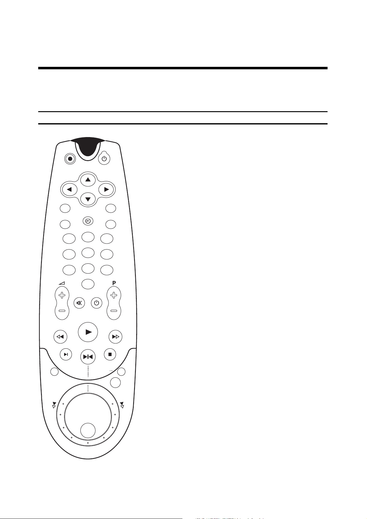
The remote control
1. BUTTONS, CONTROLS AND SOCKETS
For detailed explanations of the functions, see the corresponding chapters.
TV
1
2
3
4
5
6
7
8
9
0
OK
STOPINDEX
STILL / JOG ON
MENU
SELECT
TIMER
RECORD
CLEAR
STANDBY
PLAY
MONITOR
INSTANT
VIEW
COUNTER
g Recording
d Switching off
H / I / F / G Cursor up/down, left/right
l Call up the OSD page MAIN MENU
B Confirm entry
m Reset/clear
o TIMER programming
p Select function
O Numeric buttons
1 Rewind/picture search reverse
e Playback
2 Wind/picture search forwards
q Search index mark
ZU Still picture, Jog/Shuttle on/off
r Stop/Pause
i Picture search during fast wind
s Tape counter
a TV monitor function
å Jog/Shuttle
Additional TV functions: only for TV sets with the same remote
control code.
E TV volume +/-
Q TV sound on/off
W TV off
R TV programmes +/-
Page 3
3
ENGLISH
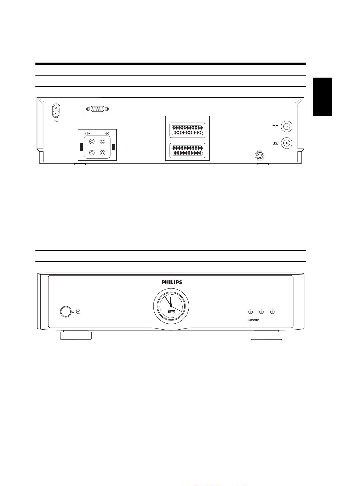
The back of the video recorder
ü Mains socket
# Socket for the connection of a cut-
ting device or a personal computer
LÄ Audio output, left/right channel
LÖ Audio input, left/right channel
cv Scart socket DEC.- AV 2
yx Scart socket EURO-AV 1
? S-VHS output socket
3 Aerial input socket
4 Aerial output socket
The front of the video recorder
Buttons and display indicators on the front cover:
ƒ Switch off/switch on
LOW POWER/STANDBY Red pilot lamp = off
Green pilot lamp = on
$
Analog clock
RECORD = Recording start indicator
TIMER = TIMER programming indicator
CASSETTE = Cassette indicator
2 EXTERNAL / DEC.- AV 2
1 EXTERNAL / EURO-AV 1
I
N
L
R
O
U
T
L
R
AUDIO
S-VHS OUT
RS 232
TIMERRECORD CASSETTE
LOW POWER
STANDBY
Page 4

4
The front of the video recorder
Buttons and connections behind the front cover:
© Video input socket (E3)
ª + º Left/Right, Audio input sockets,
(for E3 and E4)
D Synchro-edit socket
/ MEI-edit socket
† S-VHS input socket (E4)
Buttons and connections in the front cover:
ƒ Switch off/switch on
Ü Microphone level control
& Mikrophone socket
* Headphone level control
% Headphone socket
{} Recording level control, left/right
o TIMER programming on the
video recorder
p Select function
m Reset/clear
l Call up the OSD page MAIN
MENU
H / I / F / G Cursor up/down, left/right
B Confirm entry
S Automatic channel search
™
Eject cassette
å Jog/Shuttle
NM Still picture on playback,
Jog/Shuttle on/off
; Switch to camcorder mode
® Switch to video recorder
mode
( Mark beginning of scene
) Mark end of scene
1 Rewind/
reverse picture search
2 Fast forward/
forward picture search
G
Playback
g Recording
f Stop/Pause
EJECT
FOLLOW TV
R
S VHS
MEI EDIT
SYNCHRO EDITV
L
JOG SHUTTLE/STILL
PLAYER RECORDER
EDIT
RECORD
IN OUT
SELECT CLEARTIMER
MENU
OK
LOW POWER
STANDBY
RECORD LEVEL
LEFT RIGHT
MIC.
MIC.
U
U
R
E
V
E
R
S
E
F
OW
A
R
D
Page 5
2 EXTERNAL / DEC.- AV 2
1 EXTERNAL / EURO-AV 1
I
N
L
R
O
U
T
L
R
AUDIO
S-VHS OUT
RS 232
HIFI - SYSTEM
TV RF
SAT - RECEIVER
PAY - TV - DECODER oder
OUTIN
VIDEORECORDER oder
SCHNITTPULT oder
PERSONAL-COMPUTER
5
ENGLISH
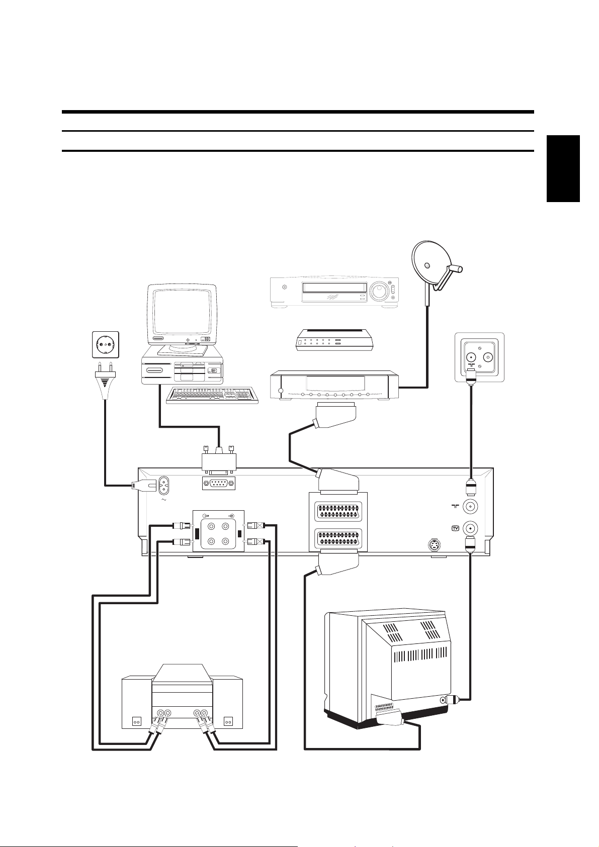
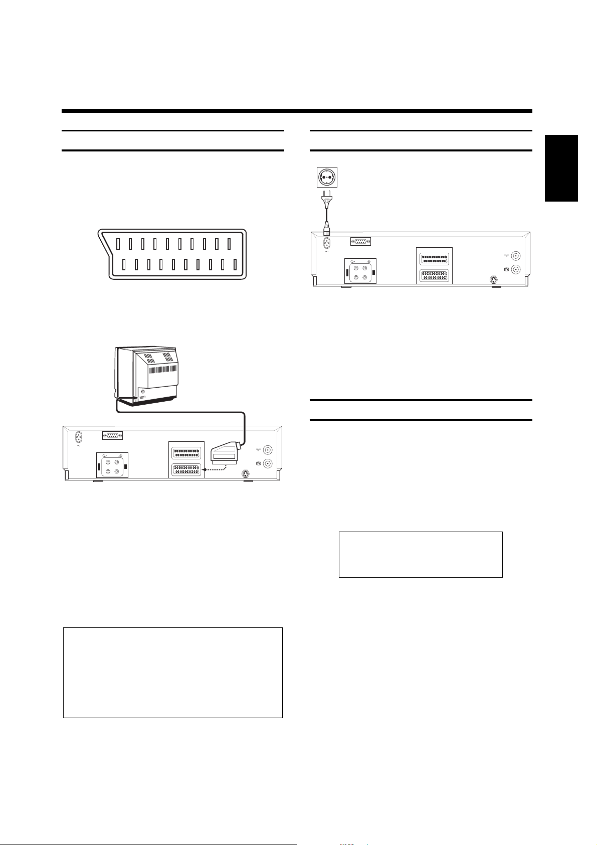
The scart socket yx has an input/output function. Connect your TV set to this socket.
The socket
cv has an input function. Connect additional units to this socket.
A detailled explanation to this illustration is to be fond in the next paragraphs.
Connecting the video recorder
2. INSTALLATION.
HOW DO I INSTALL THE VIDEO RECORDER ?
VIDEORECORDER, or
PAY-TV-DECODER, or
SAT RECEIVER
HiFi EQUIPMENT
CUTTING DEVICE, or
PERSONAL COMPUTER
Page 6
6
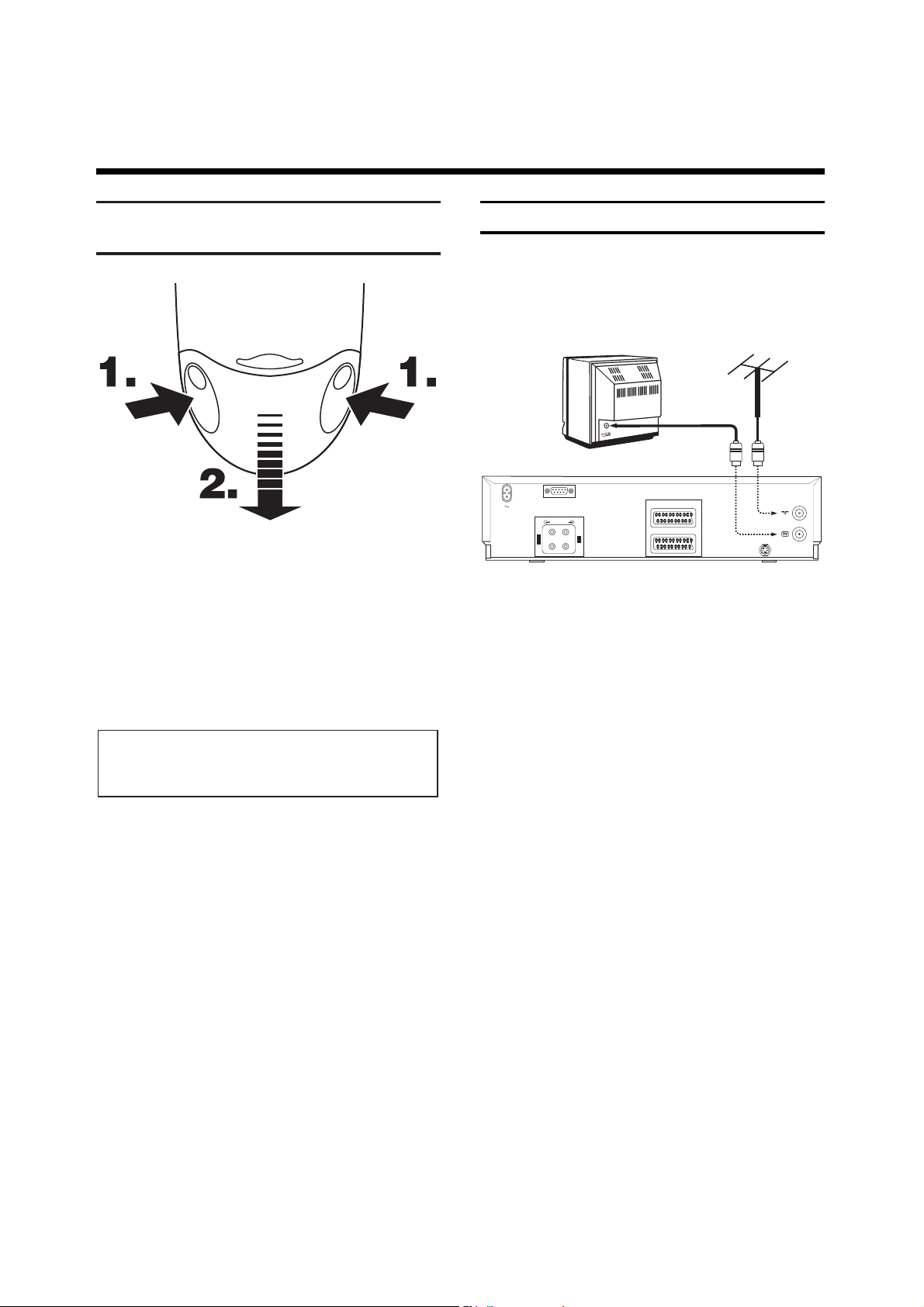
Connecting to the aerial
Your video recorder could actually be referred to as a
"TV set without picture screen".
This is why you have to connect it to an aerial as well
as to a TV set. Only then you can make recordings and
play cassettes.
!
Remove the aerial cable plug from the TV set and
insert it into the 3 socket at the rear of the
video recorder.
"
Use the aerial cable supplied to connect the 4
socket on the video recorder with the aerial input
socket on your TV set.
Both the TV set and the video recorder are now
connected to the aerial.
2 EXTERNAL / DEC.- AV 2
1 EXTERNAL / EURO-AV 1
I
N
L
R
O
U
T
L
R
AUDIO
S-VHS OUT
RS 232
Inserting the batteries into
the remote control
!
Remove the battery holder from the back of the
remote control.
To do this, squeeze the holder at the lateral marks
(1.) and pull it off (2.).
"
nsert the batteries as indicated in the battery
holder.
¤
Close the battery holder by sliding it into the
remote control until you hear a "click"
Note:
* So that the battery operates correctly, it must
always be pointed at the TV set.
Page 7
7
ENGLISH
Connecting to the mains supply
!
Insert the female plug of the mains cable into the
mains socket ü at the rear of the video recorder.
"
Insert the other plug of the mains cable into the
wall socket.
Your video recorder is now properly connected.
Some notes on operation
• The video recorder should permanently be connected to the mains supply to enable programmed
recordings and TV operation. The energy consumption is very low.
• The video recorder is automatically switched on
when inserting a cassette (the z symbol lights up
in the video recorder's display) or when pressing
the r button.
• If the video recorder is not used for a few minutes,
it is automatically switched off.
8 8
8 8:8 8:8 -:--
D W
P
EI8
VPS SVHS
STEREO I
PDC
■ ■
z
NICAM II
DEC LP
MONO HiFi
Connecting to the TV set
If your TV set does not have a Scart (Euro-AV)
socket, do not read here but continue with chapter 8,
"Additional functions of your video recorder". In the
chapter "Playback via the aerial cable" you will find the
required information.
!
Insert one plug of the Scart cable supplied into the
Scart socket t on the back panel of the
video recorder. Insert the other plug of the Scart
cable into the Scart socket on the TV set.
"
Many TV sets automatically switch over to the
programme position "EXT" (External) or "AV"
(Audio/Video) with the help of this cable
connection when playback is started on the video
recorder.
For other TV sets, select the programme position
"EXT", "0" or "AV" for video playback manually on the
TV set.
How this is done is to be found in the operating
instructions of the TV set.
Notes:
* If your TV set has several Scart sockets, select
the socket which has a video input and output
function.
* If your TV set allows for selecting the video source via a menu, select "TV" as source for this Scart
socket.
RS 232
AUDIO
L
L
O
I
U
N
T
R
R
2 EXTERNAL / DEC.- AV 2
1 EXTERNAL / EURO-AV 1
S-VHS OUT
RS 232
AUDIO
L
L
O
I
U
N
T
R
R
2 EXTERNAL / DEC.- AV 2
1 EXTERNAL / EURO-AV 1
S-VHS OUT
Page 8
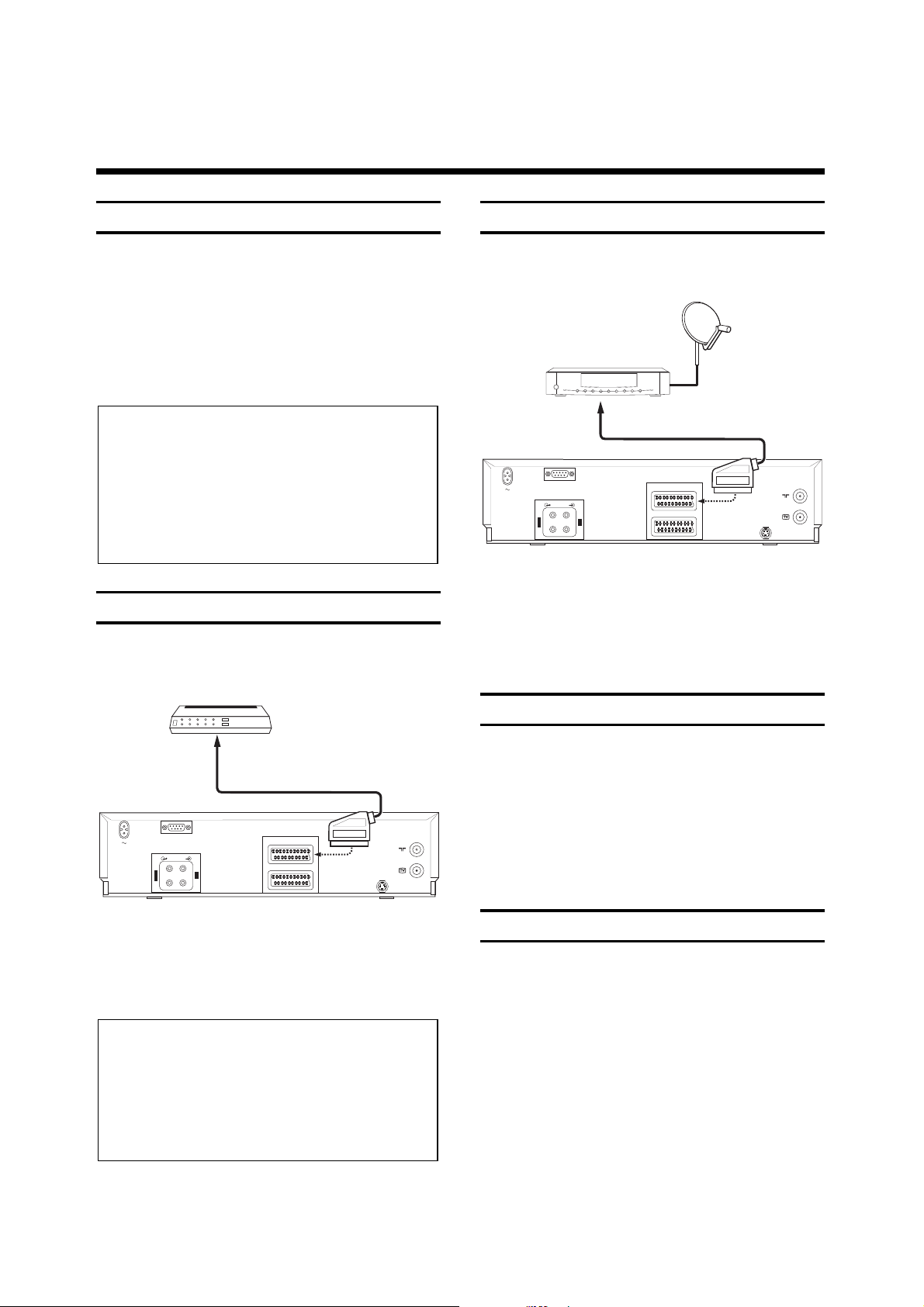
8
Connecting to a satellite receiver
It is possible to connect a satellite receiver to this video
recorder.
!
Connect the satellite receiver by means of a Scart
cable to the video recorder (socket u).
"
Switch the video recorder on and select the
programme position "E 2".
Connecting to hifi equipment
You can play the sound of your video rcorder via your
hifi equipment.
!
Connect the LÖ and
LÄ sockets on the back of your
video recorder with the corresponding sockets on
your hifi equipment.
A cable can be purchased at a specialized dealer.
Emergency interrupt
The video recorder and the remote control have an
emergency interrupt function. You can interrupt any
function by pressing the d button.
Whenever you have any problems while operating the
video recorder, you can simply interrupt any function
and start again.
You can practise using the video recorder without
worrying. No matter which button you press, you
won't damage the video recorder.
2 EXTERNAL / DEC.- AV 2
1 EXTERNAL / EURO-AV 1
I
N
L
R
O
U
T
L
R
AUDIO
S-VHS OUT
RS 232
Saving energy
There are two ways of switching off to choose from.
1. Normal switch-off.
Switch off by pressing the button ƒ. The time
remains visible.
2. Energy-saving mode.
Press the button ƒ once again.
The time in the display disappears. You can switch
back on again by pressing the same button.
Connecting to a decoder
Some TV stations transmit encoded (encrypted) signals
which you can only decode for viewing if you use a
bought or hired decoder (descrambler).
!
Connect the decoder with a Scart cable to the
u socket on the video recorder.
How to programme the decoder function when
storing TV channels is described in the chapter
"Storing TV channels".
Notes:
* It is not possible to use the decoder at the same
time for the video recorder and the TV set.
* The video recorder will automatically use the
decoder when a programme position is selected on
the video recorder which has been assigned to the
decoder function when storing TV channels.
Note:
* It is not possible to switch to energy-saving mode
as long as a TV set connected with a scart cable is
switched on. "TV ACTIVE" appears in the videorecorder's display.
* After switching the video recorder in the
„Saving energy mode“, the analogic clock cannot
set/correct itself automatically.
RS 232
AUDIO
L
L
O
I
U
N
T
R
R
2 EXTERNAL / DEC.- AV 2
1 EXTERNAL / EURO-AV 1
S-VHS OUT
Page 9
9
ENGLISH
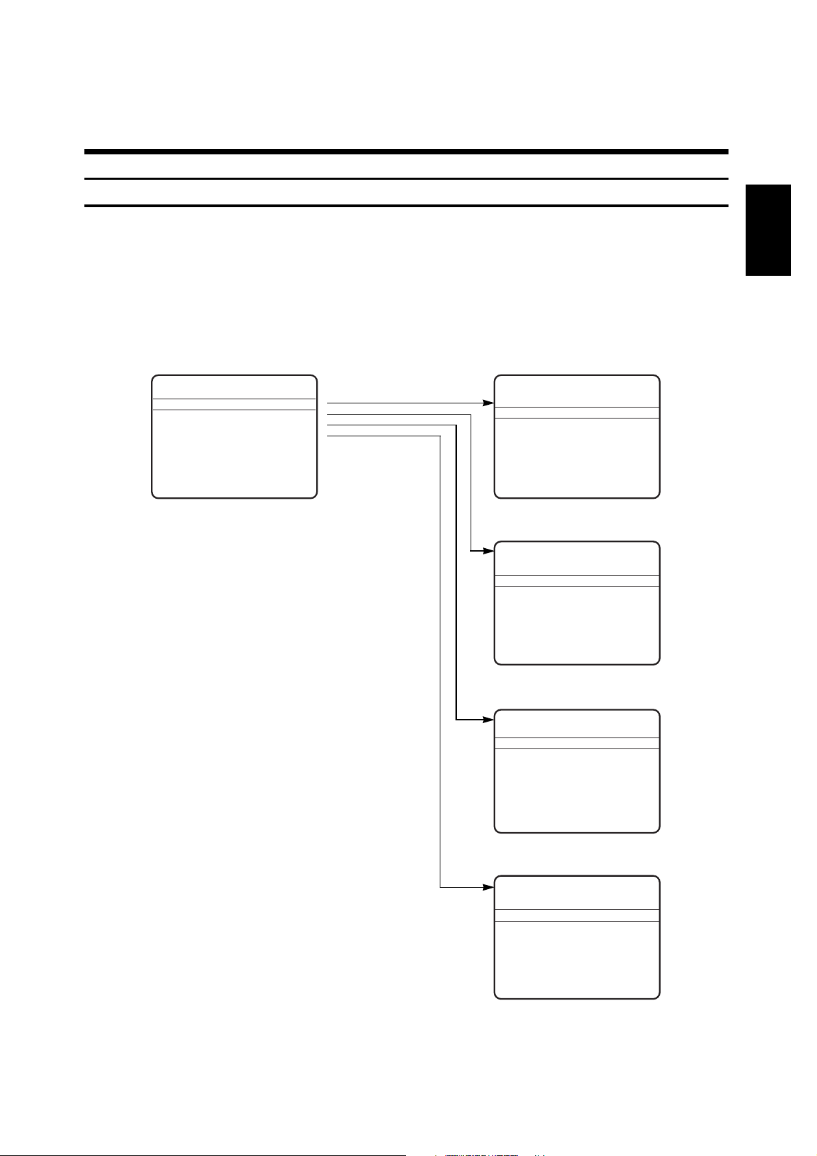
OSD – On Screen Display, the user's guide on the picture screen
The user's guide on the picture screen enables you to dialogue with your video recorder. The indications given in the
bottom line of the picture screen designate the buttons on the remote control which are to be used to carry out the
various functions. You will be guided in a simple and understandable way to the next possible operating steps.
The following example explains the user's guide with the help of the "MAIN MENU".
!
Switch the TV set on and select the programme position for the video recorder
(e.g. "EXT", "0" or "AV").
The following button s on the remote control select the
OSD pages for the user's guide:
l button
Opens the "MAIN MENU" OSD page and exits the
called up menu page.
o button
Opens and exits the "TIMER LIST" OSD page for Timer
programming.
Cursor buttons H / I up / down
Select the desired line in an OSD page.
The line is highlighted.
Cursor buttons F / G left / right
Call up OSD pages,
select data in a highlighted line step by step to the left
and right
switch data in a highlighted line.
B button
Confirms entries, calls up the next OSD page or exits
the OSD page.
G
EASY TEXTPROGRAMMING
Programme Page
01 ARD 100 100 100 100
02 ZDF 100 100 100 100
03 RTL 100 100 100 100
04 SAT1 100 100 100 100
Select programme -
^
V
Enter page - SELECT Textprog. - OK
Select page -
< > Exit - MENU
TIMER LIST
Date Prog Start End
10 ARD 20:00 21:00
10 ARTE 22:00 23:00
10 MTV 23:15 00:45
Total record time 3:30
Clear - CLEAR
Change -
> Exit - MENU
PICTURE
Tracking < >
Head cleaning
Record standard SVHS
Confirm - OK
MAIN MENU
Timer list >
Easy Textprogramming
Personal preferences
Picture
Record modes
A/V Edit
Exit - MENU
PERSONAL PREFERENCES
Timer No preference >
Record speed SP
OSD mode auto
Direct Record on
Record prepared E2
Confirm - OK
Page 10
10
3. STORING TV CHANNELS
In order that your video recorder can record
TV programmes, the TV channels (e.g. "ARD") must
first be stored in the video recorder.
You can store up to 99 TV channels.
Your video recorder has a receiver of its own. This
means it can be used independently of the TV set.
The "Easy Link" function
This function enables your video recorder to exchange
information with the TV set. For this reason, also take
note of the operating instructions that accompany your
TV set.
The TV set and video recorder (t scart
socket) must be connected using the special scart
cable supplied and your TV set must have the
"Easy Link" function.
!
Switch on the TV set.
"
Pull out the mains plug and plug it back in again.
¤
The video recorder automatically loads all of the TV
channels stored in the TV set in the correct order.
This can take a few minutes.
The following display appears on screen:
"EASY LINKL Loading from TV – please wait",
"EASY LINK" appears in the video-recorder's
display.
Once all TV channels have been found, the video
recorder switches itself off.
$
Select the desired display language. To do this,
press the button S on the video
recorder.
%
The OSD page "LANGUAGE" appears on screen.
Select the desired display language.
&
Confirm the setting by pressing the button B.
The OSD page "COUNTRY" appears on screen. Select your country.
/
Confirm the setting by pressing the button B.
"EASY LINK" appears briefly in the videorecorder
display.
It is still possible at this stage to assign special
functions to certain channel numbers. For further information, see the section "Manual search".
Automatic channel search
(ATS Euro+)
The ATS Euro + function is not possible if the connected TV set has "Easy Link".
The video recorder will make a search for all TV
channels. It stores them in a logical sequence in the
memory.
!
Switch the TV set on and select the channel number
for the video recorder.
"
Press the button S on the video
recorder.
¤
The OSD page "LANGUAGE" appears on the screen.
Select the display language desired.
$
Confirm by pressing the button B.
The OSD page "COUNTRY" appears on screen.
Choose your country.
%
Confirm by pressing the button B.
The automatic tuning begins.
&
Wait until all TV channels have been found. This
may take a few minutes.
Once all TV channels have been found, a message,
e.g. "ATS Euro+ ready 28 TV channels found"
appears on screen. The automatic channel search
is over.
/
Press the button B. The OSD page
"INSTALLATION MENU" appears on screen.
(
Complete the setting by pressing the button
l.
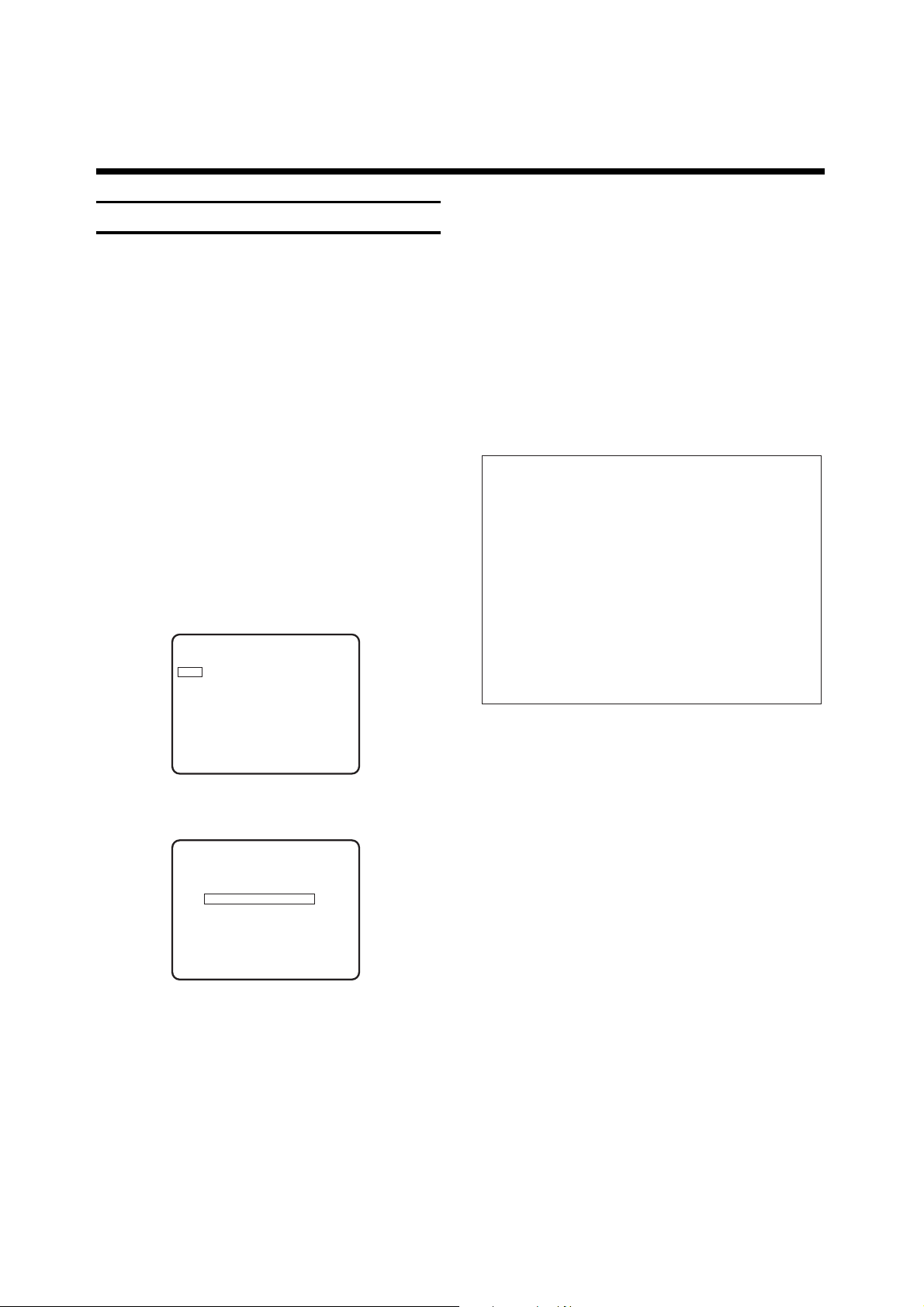
LANGUAGE
English Nederlands
Deutsch Dansk
Français Norsk
Italiano Svenska
Español Suomi
Português
"
%%
&&
!
Confirm - OK
Page 11
11
ENGLISH
For details of how to change the sequence, please
read the section entitled "Assigning TV channels".
At this stage, you can still determine special functions
for certain channel numbers. See the section "Manual
search" for further information.
Assigning TV channels automatically
(
Follow TV)
The following setting is not necessary if the TV channels have been set using the "Easy Link" function.
Only if the video recorder (socket t) and the
TV set are connected by means of a scart cable can
the TV channels be allocated automtically.
This means that the video recorder takes on the same
channel sequence as the TV set.
!
Switch the TV set on and select the channel number
for the video recorder.
"
Press the button S on the video
recorder.
¤
Select the line "Follow TV". Press the button G.
Note:
* When an ATS Euro+ is restarted, the "INSTALLATION MENU" appears after Step ".
Select "ATS Euro+" and proceed with Step &.
TV channels already stored will be retained. If the
message "FULL" appears briefly in the video recorder's display, all of the video recorder’s channel storage places have been occupied.
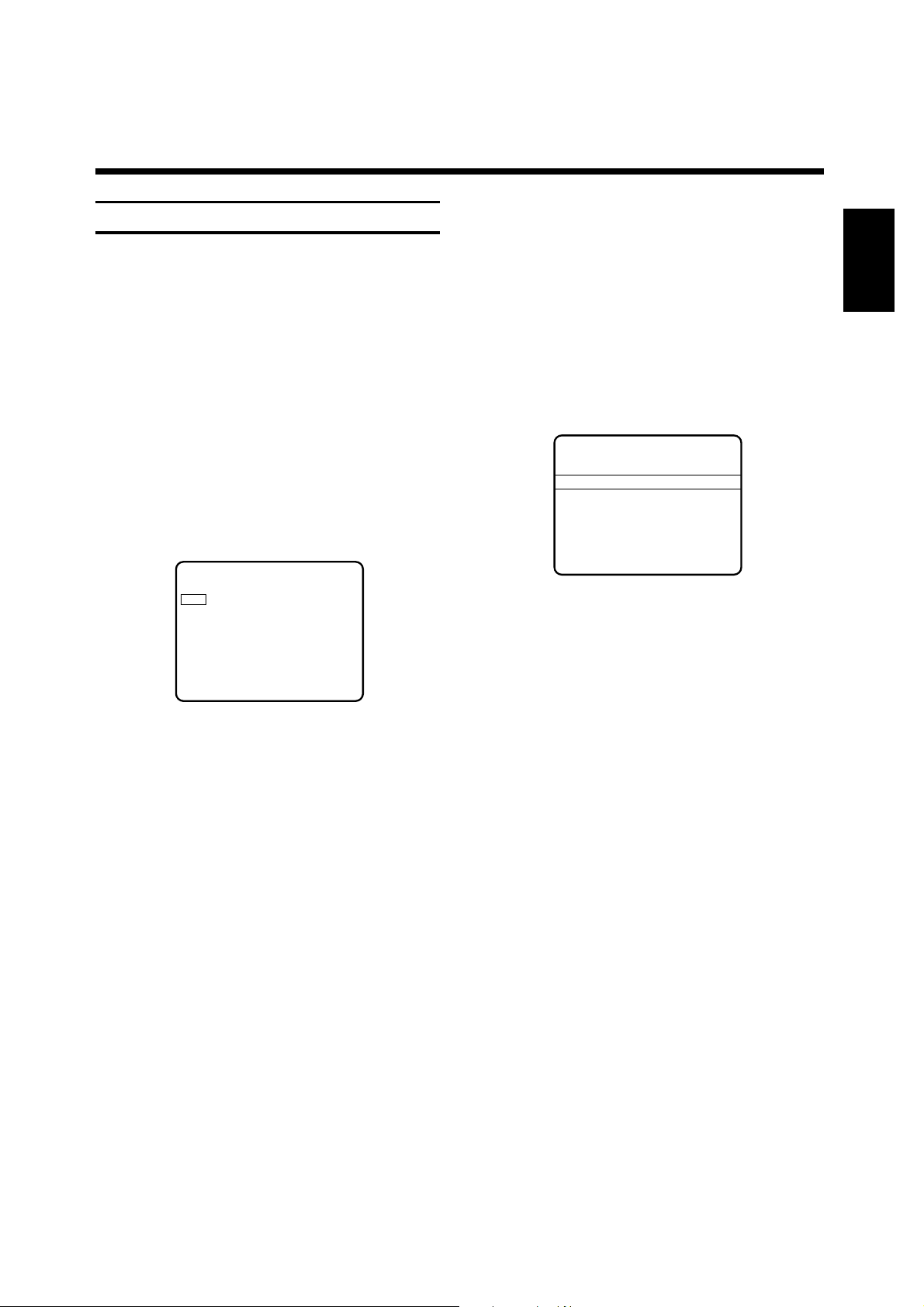
INSTALLATION MENU
TV channel list
Clock
Special settings
ATS Euro+
Follow TV >
Language
Country
Exit - MENU
$
The video recorder's display indicates
"SELECT TV P01".
%
Select the programme position "1" on the TV set.
&
Confirm with the B button on the video
recorder's remote control. The video recorder's
display indicates "WAIT". The video recorder
compares its programme positions with the
programme positions of the TV set.
If the programme position on the video recorder
and on the TV set is the same (e.g. "P 01"), the
video recorders loads the TV channel from the TV
set.
/
Wait until the video recorder's display indicates,
for example, "SELECT TV P02".
(
Select the programme position "2" on the TV set.
)
Confirm with the B button on the video
recorder's remote control. The video recorder's
display indicates "WAIT".
<:
Repeat the steps /to )until all TV channels are
allocated.
<>
Press the l button to terminate the
adjustment. The video recorder's display indicates
briefly "READY".
It is possible to assign special functions to certain programme positions. This is explained in the paragraph
"Manual search".
8 8
SE:LE:CT:TV
D W
P
028
VPS SVHS
STEREO I
PDC
■ ■
NICAM II
DEC z LP
MONO HiFi
8 8
WA:IT8:TV
D W
P
0
18
DEC VPS
LP
z ■ ■
PDC
8 8
SE:LE:CT:TV
D W
P
0I8
VPS SVHS
ST
z LP
MONO HiFi
Page 12
12
Assigning TV channels manually
The following setting is not necessary if the TV channels have been set using the "Easy Link" function.
You can allocate any TV channel found to the programme number of your choice so that you have, for example, the same TV channel sequence as on your TV set.
!
Switch on the TV set and select the programme
number for the video recorder.
"
Call up the "INSTALLATION MENU" by pressing
button S. The line "TV channel list"
becomes active.
¤
Confirm the line by pressing the button _. The
"TV CHANNEL LIST" appears. The last programme
number selected, e.g. "01", becomes active.
$
Select the TV channel that you wish to move
by pressing the button f or e.
Press the button _.
%
Using the button f or e, move the TV channel
to the desired programme number.
&
Confirm by pressing the button B. The TV
channel line is inserted and the other channel lines
are moved on a line. If you wish to cancel an
undesired TV channel, press the button m
instead of button B.
/
Sort all of the TV channel lines (steps $-
&
)
into
the desired order.
(
Complete the setting by pressing the button
l twice.
If you wish to change the basic setting, read the
detailed notes in the section "Manual search".
Note:
* You can insert "new" TV channels into the "TV
CHANNEL LIST" at a later date. For this, press the
p button in step &. Several horizontal lines
will appear to the right of the channel number.
The "new" chanel line is inserted and the following
lines are shifted one position down.
Press the _ button.
The OSD page, e.g. "CHANGE TV CHANNEL P06",
appears on the screen. Enter the data for the new
TV channel. Confirm the entry by pressing the B
button. Complete the setting by pressing the
l button twice.
TV CHANNEL LIST
PR CH NAME DEC
01 C28 ARD off
02 C25 ZDF off
03 C42 BR3 off
04 C40 SAT1 off
05 C36 RTL off
06 C21 RTL2 off
07 S18 PREM on
Insert - SELECT Move -
^
v
Change - > Confirm - OK
TV CHANNEL LIST
PR CH NAME DEC
01 C28 ARD off
02 C25 ZDF off
03 C42 BR3 off
04 C40 SAT1 off
05 C36 RTL off
06 C21 RTL2 off
07 S18 PREM on
Select -
> Exit - MENU
Page 13
13
ENGLISH
&
If you wish to set a new TV channel, press the
button _ until you have found the right one.
A changing channel or frequency number appears
on the screen.
If you know the channel transmission frequency or
channel number, the frequency (4-digit) or channel
number (2-digit) can also be directly entered using
the digit buttons k.
/
If you wish to change the basic setting of a TV
channel, select the desired line.
(
Change the basic setting by pressing the
button F or _ or by using the digit
buttons k.
)
Press the button K. The TV channel and basic
setting are stored.
<:
If you wish to search for additional TV channels,
begin again with Step $.
<>
Complete the setting by pressing the
button l twice.
CHANGE TV CHANNEL P28
Special channel on
Channel 18
Name PREM
Decoder on
Fine tuning 0
Search -
> Confirm OK
Manual search
In certain cases, the "Automatic channel search" will
not be able to find all TV channels (e.g. encoded channels).
In this case, you can set the channels using the
"Manual search" function.
!
Switch the TV set on and select the programme
number for the video recorder.
"
Call up the "INSTALLATION MENU" using button
S.
The line "TV channel list" becomes active.
¤
Confirm the line by pressing the button _. The
OSD page "TV CHANNEL LIST" appears. The last
selected programme number, e.g. "01", becomes
active.
$
Select the TV channel whose channel/frequency
number or basic setting you wish to change by
pressing the button f or e.
%
Press the button _ twice.
The channel and OSD page, e.g. "CHANGE TV
CHANNEL P28" appear on the screen.
The following basic settings can be changed:
•
the channel/special channel
•
the channel/ frequency number
•
the TV channel name,
•
the decoder assignment and
•
fine tuning of the TV channel.
Select the line "channel" or "frequency".
Depending on the selection made in the "SPECIAL
SETTINGS" menu, a channel or frequency number can
be entered. (See the section on special settings for
video recorder and TV set in Chapter 8).
TV CHANNEL LIST
PR CH NAME DEC
01 C28 ARD off
02 C25 ZDF off
03 C42 BR3 off
04 C40 SAT1 off
05 C36 RTL off
06 C21 RTL2 off
07 S18 PREM on
Select -
> Exit - MENU
Page 14

14
4. PLAYING A RECORDED CASSETTE
In chapter 2, you have learned how to connect the
video recorder to the TV set. When this is done, playback of a cassette is very easy.
If you wish to record at first, go to chapter 5.
!
Switch the video recorder and the TV set on.
When starting play on the video recorder, many TV
sets switch automatically to the programme position
prepared for video playback.
With the "Easy Link" function, your TV set is even automatically switched on from standby.
But this will only function if the video recorder is
connected via a Scart cable to the TV.
Otherwise, select the programme position intended for
video playback on the TV set.
"
Insert the cassette into the cassette compartment.
¤
Press the e button.
The display indicates " e".
$
If you wish to stop play, press the r button.
The display indicates "I I ".
%
To remove the cassette, press the V button on
the video recorder.
S-VHS or VHS Playback
The video recorder automatically recognises the
correct cassette format (VHS or S-VHS) during
playback.
When S-VHS recordings are played back, the symbol
"S-VHS" will appear in the display.
Fast forward wind and rewind
!
Press the r button. Press the 1 button
(rewind) or 2 button (wind). The tape is wound
at fast speed in the corresponding direction.
"
Press the r button as soon as the desired
tape position is reached.
Instant view
The "INSTANT VIEW" function allows you to switch to
picture search while (re)winding.
!
Switch to picture search by keeping the button
i pressed while (re)winding.
"
As soon as the button i is released,
the video recorder switches back automatically to
(re)wind.
Picture search
It is possible to select between two speeds for the
forward and reverse picture search.
!
Press the e button.
"
Repeatedly press on the 1 or 2 button until
the desired speed is obtained.
¤
Press the e button as soon as the desired
tape position is found.
Note:
* During the picture search (scan) function, the
picture quality is adversely affected and the sound
is muted.
Notes:
* Some functions are switched off automatically
after a certain time (e.g., pause, slow motion, still
picture, picture search). This is to avoid unnecessary
cassette wear and energy consumption.
* It is possible to play on this video recorder cassettes which have been recorded in NTSC standard on
other video recorders. In this case, the indication of
the tape position is not possible.
Page 15
15
ENGLISH
Still picture/super slow motion
!
Press the e button.
"
Press the ZU button. The picture
"freezes" and the display indicates " eIr ". Each
time you press the ZU button, the
still picture advances one step.
Press and hold down the ZU button.
The video recorder switches to super slow motion.
¤
Press the e button to return to normal play.
Slow motion
!
Press the ZU button.
The video recorder switches to still picture mode.
"
Press the 2 button repeatedly.
The display indicates "Ie ".
Three slow motions speeds can be selected: 1/7,
1/10, 1/14 of the normal playback speed.
When you press the 1 button several times,
you will return to the still picture.
If the button is pressed again, the slow motion
function is reversed.
The screen display will show: "rI " .
During slow motion, the sound is muted.
¤
Press the e button to return to normal play.
Adjusting the picture sharpness
It is possible to adjust the picture sharpness during
playback.
!
During playback, press the f or e button to
change the setting in the range from "3" to "–3"
("3" is the maximum sharpness).
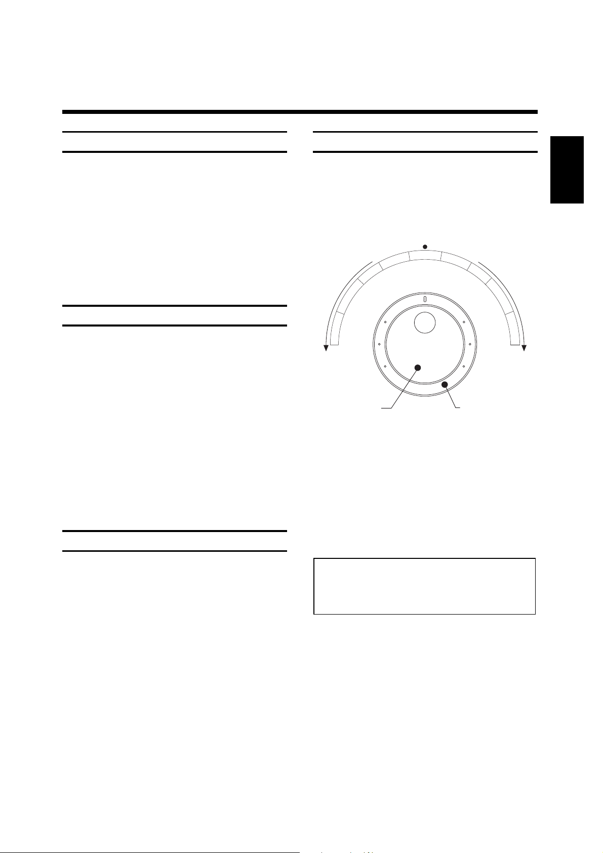
The JOG/SHUTTLE functions
There is a large rotary knob å both on the remote
control and on the video recorder.
!
Switch the function on by pressing the
NM button. A still picture is
visible on the screen.
"
Use the inner disk to select the next or previous
still picture.
¤
Turn the inner disk continuously to the right or
to the left switches to super slow motion, forward
or reverse.
$
The outer ring enables you to select different tape
speeds for the forward or reverse picture search.
%
Press the e button to return to normal play.
Note:
* During the picture search (scan) function, the
picture quality is adversely affected and the sound
is muted.
a
l
P
t
s
a
F
n
a
c
S
–
JOG
e
s
r
e
v
e
R
w
o
l
S
y
F
o
r
w
a
il
t
l
S
r
d
S
l
o
w
SHUTTLE
P
l
a
y
Fa
s
t
S
c
a
n
+
Page 16

16
Correcting picture interference.
The cleaning function
Each time you start a new playback, the video recorder
automatically adjusts the correct tracking for the
cassette.
For cassettes recorded on another recorder, it is possible to improve the automatically made optimum adjustment as follows.
!
During playback or still picture mode, press the
l button.
"
Select the menu line "Picture". Confirm with the
G button.
¤
The "PICTURE" menu appears on the screen.
The option "Tracking" (on playback) or
"Vertical jitter" (still picture) is highlighted.
$
Press the F or G button until the best picture
quality is obtained.
If horizontal interference bars cannot be removed,
proceed as follows:
%
Select the menu item "Head cleaning". Press the
G button.
The video heads are cleaned.
&
Save the setting with the B button.
/
Terminate the adjustment with the l button.
Note:
* When using cassettes of bad quality, it is possible
that interferences may occur.
Selecting the audio track, audio-mix
You can select the audio track you want to hear during
playback or in tuner mode. This is especially useful for
two-channel sound (multi-language) transmissions.
!
Press the p button. The display indicates
the current setting. If you press the p button repeatedly, you can select between four possibilities (STEREO, LEFT, RIGHT, MONO).
Surround-sound playback
If your TV set or hifi equipment is suited for surroundsound play, the video recordings will be played back
with this audio system.
Notes:
* During playback, you can select a further possibility, the "MIXMODE" function.
With this function, you will hear the mono sound of
the normal (linear) track together with the sound of
the stereo track. This enables you to play recordings which have been dubbed.
* If no stereo sound is recorded on the cassette,
the video recorder switches automatically to mono
sound.
PICTURE
Tracking < >
Head cleaning
Record standard SVHS
Confirm - OK
Page 17

17
ENGLISH
How do I know where I am currently on
the tape?
The length of the tape is indicated in minutes on
the cassette, e.g. "E180" corresponds to 180 minutes
playing time (= 3: 00 hrs).
The length indication is found on the front narrow side
of the cassette to the left. The actual playing time may
be slightly longer than indicated (e.g. 3: 05 hrs).
!
Start the tape measurement function with the
s button on the remote control.
The video recorder's display indicates "WAIT".
Then the video recorder switches, for example,
to "STOP".
The video recorder's display indicates, for example,
"P03 2:20"
"
With the s button, you can select
between the following indciations:
elapsed playing time e.g. 0:40
remaining playing time e.g. L 2:20
("L " = TIME LEFT) real time counter e.g.
0:1:45 (in hrs/min/sec).
Notes:
* When a cassette is inserted, the video recorder
must at first calculate the playing time. That is why
the display indicates at first " - : - - " and only after
several seconds tape run the playing time.
* You can set the tape counter manually to "0". Use
the s button to select the counter mode,
then press the m button.
* If a minus sign appears in front of the real time
counter (e.g., "– 0:20:00"), the tape is not wound to
its beginning.
* The indications can be read off exactly to the
minute during recording, playback and pause/stop.
Index search
The video recorder writes a mark on the tape every
time a recording is started. With the q, 1,
2 buttons on the remote control you can find these
marks on the tape.
!
Press the q and 2 buttons to find the
next mark and the q and 1 buttons to
find the previous mark. The video recorder's display
indicates "INDEX".
"
As soon as the mark is found, the video recorder
switches automatically to playback.
Intro-scan
!
Press the q and e buttons. The
video recorder's display indicates "INTRO".
"
The tape is wound to the next mark, played back
for 10 seconds, then wound to the next mark and
played back for 10 seconds, and so on.
When the end of the tape is reached, the tape is
automatically rewound to the beginning.
Notes:
* If you press any tape run button ( e.g. e
or r) during the index search or intro-scan
function, the video recorder interrupts this function.
* For recodings made without marks on another
video recorder, the index search and intro-scan
functions cannot be used.
Page 18

18
5. HOW CAN I RECORD DIRECTLY ?
If you wish to record, proceed as follows:
!
Switch the video recorder on.
Insert a cassette not protected against recording.
"
Use the I or H button to select the
programme position from which you wish to
record, e.g. "P01".
¤
Press the g button to start recording.
The video recorder's display indicates "•" and the video
recorder records the desired TV programme.
$ Press the r button to terminate recording.
Note:
* If you don not wish to record till the end of the
cassette, press the g button a second
time. The display then indicates the time when the
recording will end. Each further pressure on the
g button increases the end time in steps
of 30 minutes.
If you have pressed too often, press the m
button to return to the normal recording mode.
When the end time is reached, the video recorder
switches automatically off.
Note on TV sets with "Easy Link" function:
* The video recorder will always record the TV
programme currently selected on the TV set.
You can switch off the TV set, switch it on again
or change the programme without affecting the
recording.
Assembly editing
This function serves for joining single recordings or
scenes without disturbing transitions.
!
Press the e button. Search for the correct
position on the tape and then stop playback with
the r button. "II" appears in the display.
"
Now begin recording as usual with the g
button.
General notes:
* If recording on a S-VHS cassette should only be
made in VHS standard, then press the l button on the remote control before recording
The OSD page "MAIN MENU" appears on the
screen. Select the line "Record mode".
Confirm with the G. button. Select the line
"Record standard".
Select the "VHS" recording standard.
* The programme positions "E1", "E2", "E3" and
"E4" are intended for recordings from external
video/audio sources via the sockets
yx,
cv, © ("E3") or
† ("E4") and ª + º(audio input sockets
for "E3" and "E4"
).
* Do you wish to change to another TV programme
during recording and record this?
Interrupt the current recording with the r
button.
Select the new programme number and start the
recording with the g button.
* If a cassette protected is loaded, the video recorder switches automatically to "PLAYBACK".
* If the tape end is reached during recording, the
cassette is automatically ejected and the recorder
switches off after a few minutes.
* When making a new recording, the existing recordings on the cassette are automatically erased.
Page 19

19
ENGLISH
Direct recording with TV sets
without "Easy Link" function
If you wish to record a TV programme you are
watching, press the button g on the video
recorder when the VCR is switched-off.
The video recorder "calls up" the current programme
position number from the TV set via the Scart cable
and starts recording.
Erase protection
So that you don't accidentally delete an important
recording, you can remove the special tab (erase
protection) on the front of the cassette with a
screwdriver or slide it to the left.
Later, if you no longer want the erase protection, you
can seal the gap once more with adhesive tape or slide
the tab to the right.
Notes:
* In order for "Direct Record" to function, it must be
switched to "on" as described in Chapter 8 in the
section entitled "Personal preferences" .
* The video recorder must be connected via a Scart
cable to an appropriate TV set.
* Not all external units (e.g. certain satellite
receivers, Pay-TV decoders) are appropriate for the
"Direct recording" function.
* Select another programme number on the TV set
not until "READY" appears in the video recorder's
display.
Longplay function
You can reduce the recording speed by half. This
makes it possible to record, for example, 8 hours
instead of 4 hours with an "E240" cassette.
!
To do this, you must select "LP" for the tape speed
in paragraph "Personal preferences" in chapter 8.
The video recorder's display indicates "LP".
"
When starting playback, the video recorder will
automatically select the correct tape speed.
HiFi stereo reception
This video recorder can record and play back stereo
broadcasts. Playback then is in HiFi quality.
Notes:
* You will get the best picture and sound quality if
you record with standard speed ("SP").
* During picture search, still picture, super slow
motion and slow motion, playback is not in colour.
Page 20

20
6. HOW DO I PROGRAMME A RECORDING?
In this chapter you will learn how to programme the
video recorder. It switches itself on automatically,
records the TV programme you want, and then
switches itself off again automatically.
What information is required by the video recorder?
For every programmed recording, you must give the
video recorder the following information:
* the date on which the recording is to be made
* the programme number for the TV programme
* the start time of the recording
* the end time of the recording
* VPS/PDC on or off
If you use "Programming with ShowView", you need
only enter the ShowView code. This code contains the
complete information the recorder needs. The
"ShowView guide numbers" are automatically
allocated on this video recorder.
The video recorder stores all of the information it
requires for recording in what is known as a TIMER
block. It can store this information up to four weeks in
advance.
Your video recorder can store up to 6 of these TIMER
blocks.
Make sure that the times of the TIMER blocks do not
overlap. The video recorder first must finish one TIMER
block before starting the next block.
What is
"PDC"(Programme Delivery Control) and
"VPS" (Video Programme System) ?
With VPS and PDC, the TV station controls when the
video recorder is switched on and off. This means that
the video recorder switches itself on and off at the
right time even if a TV programme you have programmed begins earlier or finishes later than expected.
You can see if a TV station is transmitting a VPS or
PDC code if "VPS" or "PDC" appears in the display on
the video recorder when the recorder is switched to
"STOP".
If you wish to use VPS/PDC, the "VPS/PDC" indication
must be switched on in the following paragraph. If you
do not wish to use VPS/PDC, the "VPS/PDC" indication
must be switched off.
Notes:
* With VPS/PDC, two subsequent TV broadcasts on
the same programme position can only be programmed as two separate TIMER blocks.
* The first few seconds of a programme intended
for recording will be missing if the switch-on
command transmitted by the TV station is late.
* VPS/PDC only works as it should if television
reception is good. If reception conditions are less
than optimum (e.g. if you use a room aerial),
VPS/PDC may not function as it should; this does
not indicate that your video recorder is not functioning properly.
Page 21

21
ENGLISH
Programming with "ShowView"
This method makes programming your video recorder
as easy as dialing a telephone number.
All you need to do is enter the (three- to nine-digit)
ShowView code which is printed in your TV guide next
to the starting time for the TV programme.
You can programme with the buttons on the video
recorder and/or on the remote control handset.
Be sure you have inserted a cassette without erase
protection.
!
Switch on the TV set and select the programme
position intended for the video recorder.
"
Press the o button on the remote control.
The OSD page "TIMER" appears on the picture
screen.
¤
Select the option "ShowView". Confirm with the
G button.
$
The OSD page "SHOWVIEW" appears on the
picture screen.
%
Enter the ShowView code with the numeric
buttons O. If you make a mistake, use the
m button to correct it.
&
If you wish to programme daily or weekly
recordings, use the p button to select the
"daily" or "weekly" option.
Daily recordings can be programmed only for the
weekdays Monday through Friday.
/
Press the B button. The programmed code now
is deciphered. After the code has been deciphered
correctly, the corresponding information appears on
the picture screen and in the display on the video
recorder.
(
Have you entered all the data correctly?
If you have, press the B button.
"Timer ready" appears briefly in the screen display.
The symbol "Å" appears in the video recorder's display.
It indicates that a TIMER has been programmed.
)
Terminate programming with the d
button.
Some important information:
* If you wish to use the programme number "E2" in
order to record from an external source (e.g. from a
satellite receiver), confirm the programme number
"E2" indicated in Step /by pressing the button
B
* If "CODE ERR" appears in the display,
the numerical code is wrong or has been entered
wrongly. Repeat the entry or terminate by pressing
the button d.
* If "SET CLOCK" appears in the display, the internal
clock of the video recorder has not been set. Set the
clock.
* Daily recordings can only be programmed for the
weekdays Monday to Friday.
* In the case of "daily/weekly" programming, the first
recording must be made within the first week.
* Some TV programmes go on for longer than
advertised. If you wish to enter a later end time, select "End" using the button _ in Step /and enter
the end time using the button f or e or the digit
buttons k.
* The "SHOWVIEW" menu appears straight after
Step "if you have set the display "ShowView" on
the OSD page "PERSONAL PREFERENCES".
(See Step %of the section "Personal preferences"
in Chapter 8).
Notes:
* When programming with ShowView for the first
time, the programme position "E 2" is used.
On the picture screen appears the message
"Please enter programme number".
Use the I or H button to select the "correct"
programme position number (e.g. "Prog 01" for
"ARD"). Confirm with the B button.
The video recorder will use this programme number
for all future ShowView programmings for this TV
channel.
* The "VPS/PDC" function can be switched on and
off with the p button. Press the G button
* If you wish that "subtitles" are also recorded,
press the p button. Enter the number of the
subtitles page as three digits with the numeric buttons O.
SHOWVIEW
– – – – – – – – –
Date Prog Start End
– – – – – –:– – – –:– –
once
D daily
W weekly
/ /D/W - SELECT Confirm - OK
Page 22

22
Programming with TXT pages
With the help of the remote control handset, the onscreen user's guide and the page memory, TIMER
programming is considerably facilitated. The general
use of the TXT decoder is to be found in the chapter
"Additional functions" later in this booklet.
You can programme with the buttons on the video
recorder and/or on the remote control handset.
Be sure you have inserted a cassette without erase
protection.
!
Switch on the TV set and select the programme
position intended for the video recorder.
"
On the video recorder, select the TV programme
position from which you wish to make TIMER
recordings.
¤
Press the l button.
$
Select the option "Easy Textprogramming". Confirm
with the G button.
%
The OSD page "EASY TEXTPROGRAMMING"
appears on the picture screen. The last selected
programme position (e.g. "01 ARD") and a page
number (e.g. "301") are highlighted.
&
Select the programme position from which you
wish to record. If necessary, select another page
number.
/
Start TXT programming with the B button.
The TXT page appears on the picture screen.
The starting time of the first TV programme is
marked by a cursor ■.
If the cursor ■does not appear (e.g. on subpages),
press the B button.
If necessary, select another page number.
(
Select the desired TV programme.
The cursor ■ marks the start time of the selected
TV programme.
)
Confirm with the B button
.
The picture screen and the video recorder's display
indicate the TIMER data.
<:
If you wish to programme daily or weekly
recordings, select the line "daily" or "weekly" using
the p button
.
Either "D" or "W" also appears beside the date. Daily
recordings can only be programmed for the weekdays Monday to Friday.
<>
Press the G button.
If you wish that "subtitles" are also recorded, press
the p button . Enter the number of the subtitles page as three digits with the numeric
buttons O.
<Y
Confirm with the B button.
"Timer ready" appears briefly in the screen display.
If you wish to programme further recordings, restart
with step &.
<X
Terminate programming with the d
button. The symbol "Å" appears in the video recorder display. It indicates that a TIMER has been programmed.
Notes:
* If "SET CLOCK" appears in the display, the internal clock of the video recorder is not set. Set the
clock.
* If "DAILY ERR" appears in the display, you have
programmed a TV programme with the first recording on a Saturday or Sunday as "daily". This is not
possible.
* Daily recordings can only be programmed for the
weekdays Monday to Friday.
* For "daily/weekly" programming, the first
recording must be scheduled within one week.
EASY TEXTPROGRAMMING
Programme Page
01 ARD 301 302 303 304
02 ZDF 100 100 100 100
03 RTL 100 100 100 100
04 SAT1 100 100 100 100
Select programme -
^
V
Enter page - SELECT Textprog. - OK
Select page -
< > Exit - MENU
Page 23

23
ENGLISH
TIMER Programming (Standard Timer)
Data on six recordings can be entered and stored in
the video recorder. The OSD page on screen or the
video recorder display will lead you "step by step" to
the next and possible data entry.
The data is stored in the next free TIMER block of the
video recorder.
You can programme with the buttons on the video
recorder and/or on the remote control handset.
Ensure that a cassette without erase protection is
inserted.
!
Switch on the TV set and select the programme
number for the video recorder.
"
Press the remote control button o. The
OSD page "TIMER" appears on screen.
¤
Select the line "Standard Timer". Confirm this by
pressing the button _.
$
The OSD page "TIMER" appears on screen.
The following appears in the insert line:
"today´s" date, the current time as a start time and
the current time plus "1:30 hours" as an end time.
%
If you wish to programme daily or weekly
recordings, select the line "daily" or "weekly" using
the button p.
Either "D" or "W" also appears beside the date.
Daily recordings can only be programmed for the
weekdays Monday to Friday.
&
Enter the data using the digit buttons k, or
confirm the date by pressing the button _.
/
If you wish that "subtitles" are also recorded,
press the p button . Enter the number of
the subtitles page as three digits with the numeric
buttons O.
(
Enter the number of the TV programme using the
digit buttons k.
)
The "VPS/PDC" function can be switched off and
back on again by pressing the button p.
<:
Enter the start time using the digit buttons k.
<>
Enter the end time where necessary.
<Y
When you have entered all data correctly, press
the button K.
"Timer ready" appears briefly in the screen display.
The symbol "Å" appears in the video recorder display. It
indicates that a TIMER has been programmed.
If you wish to programme additional settings, repeat
Steps "– <Y.
<X
Terminate programming with the d
button.
Some important information:
* If "SET CLOCK" appears in the display, the internal clock of the video recorder has not been set.
Set the clock.
* Daily recordings can only be programmed for the
weekdays Monday to Friday.
* In the case of "daily/weekly" programming, the
first recording must take place within the first
week.
* The "TIMER" menu appears straight after Step
"
if you have set the display "Standard Timer" on the
OSD page "PERSONAL PREFERENCES".
(See Step %of the section "Personal preferences"
in Chapter 8).
TIMER
Date Prog Start End
01 – – 20:15 21:45
once
D daily
W weekly
/ /D/W - SELECT Confirm - OK
Page 24

24
How can I record from a
satellite receiver?
It is also posssible to programme recordings from an
external satellite receiver.
!
Connect the satellite receiver with the socket
u. Make sure that the satellite receiver
is switched on and tuned to the desired satellite
station.
"
Programme a TIMER block using one of the already
described methods. Select the programme position
"E2" for the external programme source (satellite
receiver).
2 EXTERNAL / DEC.- AV 2
1 EXTERNAL / EURO-AV 1
I
N
L
R
O
U
T
L
R
AUDIO
S-VHS OUT
RS 232
Note:
* If you use "Programming with ShowView" for the
Timer recording from the "external" satellite
receiver, the video recorder selects automatically
the programme position "E2".
In this case, you can ignore the message
"Please enter programme number".
A few general notes on programming
•
The programmed recording will always be effected
with the recording speed (SP or LP) selected in the
OSD page "PERSONAL PREFERENCES".
•
If you have forgotten to insert a cassette before
programming, the recorder's display indicates
"NO CASS".
•
If you insert a cassette with erase protection for
the recording, the indication "PROTECTED" briefly
appears in the video recorder's display after you
have finished programming. The cassette is then
ejected.
•
TIMER recording is only possible if the video
recorder is switched off. If the video recorder is
switched on before a programmed recording, the
message "TIMER REC" flashes in the display.
•
If the recording times of the TIMER blocks overlap
each other, the message "COLLISION" appears in
the video recorder's display.
In this case , you must correct or clear the data of
one TIMER block. How this is done is explained in
the paragraphs "How can I check, clear or correct a
TIMER block?"
•
If you have programmed all TIMER blocks, the
message "FULL" appears in the video recorder's
display. Refer to the paragraphs "How can I check,
clear or correct a TIMER block?
•
If the end of the cassette is reached during a
TIMER recording, the recorder ejects the cassette.
The video recorder's display indicates "TIMER
REC".
Insert a "new" cassette into the video recorder then
press the d button on the remote control to resume the TIMER recording.
•
If TIMER recordings are programmed, the video
recorder cannot be switched in the "save energy
mode"
Page 25

25
ENGLISH
How do I stop a TIMER recording ?
While a programmed recording is running, the drive
mechanism buttons of the video recorder are blocked.
If you want to stop the running recording, press the
d button.
How can I check a TIMER block ?
!
Switch on the TV set and select the programme
position intended for the video recorder.
"
Press the l button. The OSD page "MAIN
MENU" appears on the picture screen.
¤
Select the option "Timer list". Confirm with the G
button.
$
The OSD page "TIMER LIST" appears on the picture
screen.
Check all of the TIMER data. If the data is correct,
press the d button to terminate.
How can I clear or correct a TIMER
block ?
!
Switch on the TV set and select the programme
position intended for the video recorder.
"
Press the l button on the remote control.
The OSD page "MAIN MENU" appears on the picture screen.
¤
Select the option "Timer list". Confirm with the G
button.
$
The OSD page "TIMER LIST" appears on the picture
screen.
%
Do you wish to clear a TIMER block?
If yes, select the desired line (TIMER block) with
the I or H button. Press the m button to
clear the TIMER block.
&
Do you wish to correct a TIMER block?
If yes, select the desired line (TIMER block) with
the I or H button. Press the G button.
/
The OSD page "TIMER" appears on the picture
screen.
Use the F or G button to select the TIMERdata (Dat., Prog., Start or End) you wish to correct.
(
Correct the data with the numeric buttons O or
with the I or H button.
)
Have you entered all data correctly?
If yes, press the B button on the remote
control.
"Timer ready"
appears briefly in the screen display
and is followed by the OSD page "MAIN MENU".
<:
Terminate programming with the l or
d button.
TIMER LIST
Date Prog. Start End
10 P14 20:00 21:00
- - - - - - : - - - - : - -
Total record time 1:00
Clear - CLEAR
Change -
> Exit - MENU
TIMER
Date Prog. Start End
10 P14 20:00 21:30
Confirm - OK
Page 26

26
Sorting TV programmes for
TIMER programming
Do you prefer certain TV programmes for TIMER
recording?
With the Sort function, you can create a separate programme list to your preferences.
!
Switch on the TV set and select the programme
position intended for the video recorder.
"
Press the l button. The OSD page "MAIN
MENU" appears on the picture screen.
¤
Select the option "Easy Textprogramming".
Confirm with the G button.
$ The OSD page "EASY TEXTPROGRAMMING"
appears on the picture screen. A page number
of the last selected programme number is highlighted.
Use the F button to select the programme number.
The programme number and the programme name
are highlighted.
% Select your favourite TV programme from which
you wish to make most of your TIMER recordings.
& Press the p button. The programme name
disappears and two horizontal lines appear in the
place of the programme number.
Note:
* The programme order stored in the video
recorder is not changed. Only the TV programmes
in the OSD page "EASY TEXTPROGRAMMING" are
brought in a new order.
/ Enter the programme number "01" as two digits
with the numeric buttons O. After the entry of
the second digit, the two TV programmes are
exchanged.
( Select the TV programme you wish to appear at the
second position in the list.
Repeat the steps % to / until your favourite TV
programmes are in the desired order.
) Complete the setting by pressing the button
l twice.
EASY TEXTPROGRAMMING
Programme
Page
14 ARTE 100 100 100 100
15 CNN 100 100 100 100
- - 100 100 100 100
17 ZDF 301 302 303 304
18 PREM 100 100 100 100
Enter programme - 0 - 9
Exit
- MENU
EASY TEXTPROGRAMMING
Programme Page
01 ARD 100 100 100 100
02 ZDF 100 100 100 100
03 RTL 100 100 100 100
04 SAT1 100 100 100 100
Select programme -
^
V
Enter page - SELECT Textprog. - OK
Select page -
< > Exit - MENU
Page 27

27
ENGLISH
7. EDITING VIDEO RECORDINGS
Audio Dubbing
It is possible to dub (overscore) another sound
recording onto the audio track of an existing recording
at a later date.
To do this connect a sound source (e.g. CD player) to
the ª + º input sockets or a microphone to the
& socket. The sockets are at the front of the video
recorder behind a flap.
Insert the recorded cassette into the video recorder.
Make sure the cassette is not protected against
recording!
!
Press the l button. Select the "A/V Edit"
line. Confirm with the G button.
"
The OSD page "EDIT MENU" will appear on the
screen. Select the line "Audio dubbing".
Confirm with the G button.
¤
The OSD page "AUDIO DUBBING" will appear on
the screen.
If you want to fade the sound in or out, select the
corresponding line "Fade in" or "Fade out".
Switch to "on" with the G button.
Select the line "Start dubbing".
Confirm with the G button.
$
Find the position where you want the recording to
end in playback mode.
End the search with the ZU
button. Set the display to "0:00:00" (= Edit out)
with the ) button.
%
Using reverse picture search find the position
where audio dubbing is to start.
&
Press the r button.
/
Switch the sound source on.
Use the slider control {} or
Ü on the video recorder to adjust the
recording level so that the "0 dB" mark lights up
during the loudest passages of the recording.
It is not possible to simply cut video tapes with a pair
of scissors then splice them.
If you wish to join and/or insert new scenes without
disturbing transitions and exactly to the picture into
existing recordings, it is necessary to use an electronic
cutting facility when copying from one video tape to
another.
This creation of "new" video recordings is called
"editing". For editing, different methods can be used.
Audio dubbing
This means that an appropriate sound is added to an
existing video recording.
With this function, it is possible to replace the mono
sound track on the video tape with another sound. The
old mono track is completely erased. The stereo sound
track and the video recording remain unchanged.
The insert and insert-edit functions
With the insert functions, it is possible to conveniently
insert other picture and/or sound recordings into
existing recordings without disturbing transitions.
You have the choice between three insert functions.
Synchronous editing (synchro-edit)
When copying between this video reocorder and a
second video recorder or camcorder being
correspondingly equipped, this function provides for a
synchronous start of both units.
This ensures that every scene will be copied exactly
to the picture and without disturbing transitions.
The programme edit functions
You can mark up to ten (10) individual scenes from existing video recordings, transfer to the "Programme
Edit" list of the video recorder, rearrange and
afterwards re-record one after the other onto a video
cassette.
It is a prerequisite that your camcorder is equipped
with a "Bus control" and has an hour, minute, second
or single picture counter (time code counter).
Page 28

28
(
Start dubbing with the g button at the
right time.
The video recorder will start to record the sound from
the sound source. The audio track will be re-recorded.
It is possible to monitor the sound recording via a
headphone connected to the % socket.
Adjust the volume level of the headphone with the
slider control * on the video recorder.
The audio recording stops automatically when the
display counter reaches "0:00:00" (=Edit out).
)
If you want to abort, then press the
r button.
<:
End audio dubbing with the l or
d button (remote control).
Notes:
* To play back the audio dubbing sound press the
p button repeatedly until "MONO" appears
in the video recorder's display.
* If you connect an audio mixer to the video recorder, you can mix the original hifi sound on the video
cassette with the sound from several external
sound sources. The original hifi sound can be taken
from the LÄ Cinch sockets (at the
rear of the video recorder) and passed to the audio
mixer.
Connect the audio mixer to the Cinch sockets
ª + º (front of video recorder).
Start playback on the video recorder.
Use the slider controls {} to
adjust the recording level from the audio mixer so
that the "0 dB" mark lights up during the loudest
passages of the recording.
* To hear the dubbed sound, you must select the
Mono track for playback.
Page 29

29
ENGLISH
¤
Search the desired end of the insert recording on
the cassette in the video recorder.
Press the r button. Use the s
button to select the counter mode.
Press the m button to reset the tape
counter to "0:00:00".
$
Search the desired beginning of the insert
recording on the cassette in the video recorder.
Press the r button.
%
Switch on the external video/audio source. Search
the beginning of the insert recording.
&
Press the l button.
Select the option "Record modes".
Confirm with the G button.
The OSD page "RECORD MODES" appears on the
picture screen.
If the picture/sound source is connected to the
input sockets © ('E3') or † ('E4') and
ª + º (audio input for "E3" and "E4"):
Use the slider controls {} to
adjust the recording level so that the "0 dB" mark
lights up during the loudest passages of the
recording.
If the picture/sound source is conected to the
t or u socket, the recording level
is adjusted automatically.
/
Select the desired insert function:
"Insert Dubbing" or "Insert Video" or
"Insert Copy".
Select the programme position for the connected
video/audio source ("E1", "E2", "E3" or "E4").
Follow the user guide on the OSD page.
(
Start the insert recording at the "correct" moment
with the g button.
)
The insert recording is automatically stopped
when the tape counter has reached "0:00:00".
<:
Press the l button or the d
button (remote control) to terminate the recording.
Note on "INSERT VIDEO":
* To start playback of the "original" sound, repeatedly press the p button on the remote control
until the video recorder's display indicates "MONO".
The insert functions
With the insert functions, it is possible to conveniently
insert other picture and/or sound recordings into
existing recordings.
Connect the video/audio source to the input sockets
© ("E3") or † ("E4") and ª + º(audio input
sockets for "E3" and "E4") of the video recorder.
The sockets are located behind the flap at the front of
the recorder, or
connect the video/audio source to the Scart sockets
t or u of the video recorder. The
sockets are located on the back of the video recorder.
You have the choice between three insert functions.
• "INSERT DUBBING": the picture, the hifi sound (heli-
cal track), and the mono sound (longitudinal track)
are newly recorded.
• "INSERT VIDEO": the picture and the hifi sound
(helical track) are newly recorded, the mono sound
(longitudinal track) is maintained.
• "INSERT COPY": the picture is newly recorded.
The mono sound (longitudinal track) is retained and
transferred onto the hifi track (helical track).
Please also see the operating instructions of the
connected unit.
Insert the recorded cassette into the video recorder.
Make sure the cassette is not protected against
recording!
!
Switch on the TV set and select the programme
position intended for the video recorder.
"
Switch the video recorder on.
Page 30

30
Adjusting the video recorder (VCR) to
the camcorder (CC) (edit-setup)
You can synchronously copy between this video
recorder (VCR) and an appropriately equipped camcorder (CC). Both units are started at the same time with
the help of a synchronous impulse and an adjustable
start delay (= preroll time).
Various operating and cabling variants are possible. You
will find an overview of the synchro-edit cables at the
end of this operating manual.
Connect the two units with the corresponding synchroedit cable (socket D or / on
your video recorder).
Connect the video/audio source to the input sockets
© ("E3") or † ("E4") and ª + º(audio input
sockets for "E3" and "E4") of the video recorder.
The sockets are to be found behind the flap at the front
of the recorder.
Please also observe the operating instructions of the
camcorder.
Insert a cassette without erase protection into the
video recorder
!
Switch on the TV set and select the programme
position intended for the video recorder.
"
Switch the video recorder on.
Select the programme position "E3" or "E4".
¤
Press the l button. The OSD page "MAIN
MENU" appears on the picture screen.
Select the menu option "A/V Edit".
Confirm with the G button.
$
The OSD page "EDIT MENU" appears on the
picture screen; the option "Edit Setup" is
highlighted.
Confirm with the G button.
Follow the user guide on the OSD page.
%
Switch the camcorder to still picture (playbackpause).
&
Press the B button on the video recorder's
remote control. Wait until the video recorder has
recognized the connected camcorder.
Follow the user guide on the OSD page.
/
You can call up the default start delay (= preroll
time) for the connected camcorder type by
pressing the m button. It is then possible to
alter the preroll time with the F or G button.
Press the I button.
(
Select the desired insert edit function:
"Insert Dubbing" or "Insert Video" or
"Insert Copy".
)
Confirm with the l button.
Synchronous editing (synchro-edit)
!
Call up the OSD page "EDIT MENU".
Use the I button to select the option "Synchro
Edit". Confirm with the G button.
"
The OSD page "SYNCHRO EDIT" corresponding
to the connected camcorder type appears on the
picture screen.
¤
Use the ® button to select the OSD
page "Recorder" (for video recorder mode).
Search the beginning of the recording on the video
recorder.
Switch the video recorder to playback-pause.
$
Use the ; button to select the OSD page
"Player" (for camcorder mode).
Search the beginning of the recording on the
camcorder.
Use the slider controls {} to
adjust the recording level so that the "0 dB" mark
lights up during the loudest passages of the
recording.
Switch the camcorder to still picture (playbackpause).
Follow the user guide on the OSD page.
The way copying is started depends on the camcorder
and the corresponding synchro-edit cable used.
Note:
* The start delay (= preroll time) must be adjusted
only once. The video recorder will save this setting.
Keep in mind that other camcorder types must also
be adjusted when being used the first time.
Page 31

31
ENGLISH
Variant 1 as shown in figure Á or figure
Ò if the video recorder is to control the
camcorder.
%
Start copying with the g button on the
video recorder.
The camcorder starts with "PLAYBACK" and at
the same time the video recorder starts with
"RECORDING".
&
Stop copying with the r button on the
video recorder.
/
End copying with the l button or the
d button on the remote control.
Notes:
* If the beginning of the scene is missing, the preroll time is too long. Set a shorter time.
If recording is started too soon (before the scene to
be copied), the preroll time is too short. In this
case, the preroll time must be increased.
* If your camcorder is equipped with a 2.5 mm ø
control socket (LANC control) or a 5-pin MEIsocket, the playback and fast wind functions of
many camcorders can be controlled with the corresponding control elements on the video recorder.
Á
Ò
3 x Cinch
3 x Cinch
S-VHS
3,5mm/
2,5mm
2,5mm
SynchroEdit
SYNCHRO EDITV
MEI EDIT
L
R
S VHS
MEI EDIT
SYNCHRO EDITV
MEI EDIT
L
R
S VHS
S-VHS
Page 32

32
Variant 2 as shown in figure ¦ or figure
¢ if the camcorder is to control the
video recorder.
%
Start copying with the corresponding button on the
camcorder or its remote control.
The camcorder starts with "PLAYBACK" and at
the same time the video recorder starts with
"RECORDING".
&
Stop copying with the PAUSE or STILL button on
the camcorder or on its remote control.
/
End copying with the l button or the
d button on the remote control.
Notes:
* If the beginning of the scene is missing, the preroll time is too long. Set a shorter time.
If recording is started too soon (before the scene to
be copied), the preroll time is too short. In this
case, the preroll time must be increased.
¦
¢
8 PIN
A/V
Synchro
S-VHS
3,5mm/
2,5mm
SYNCHRO EDITV
MEI EDIT
L
R
S VHS
20 PIN
A/V
Synchro
3,5mm/
2,5mm
SYNCHRO EDITV
MEI EDIT
L
R
S VHS
Page 33

33
ENGLISH
Please also see the operating instructions of the camcorder.
Insert the recorded cassette into the video recorder.
Make sure the cassette is not protected against
recording!
!
Switch on the TV set and select the programme
position intended for the video recorder.
"
Switch the video recorder on.
Select the programme position "E3" or "E4".
¤
Press the l button.
The OSD page "MAIN MENU" appears on the
picture screen. Select the menu option "A/V Edit".
Confirm with the G button.
$
The OSD page "EDIT MENU" appears on the
picture screen. Select the option "Insert Edit". Confirm with the G button.
The OSD page "INSERT EDIT" corresponding to the
connected camcorder type appears on the picture
screen.
Follow the user guide on the OSD page.
%
Provided your camcorder has a 2.5 mm ø control
socket (LANC control) or a 5-pin MEI-socket:
Confirm the menu option "Insert VCR" or
select the option "Insert CC".
Confirm with the G button.
Methode 1 'Insert VCR':
&
Use the ® button to select the OSD
page "Recorder" (for video recorder mode).
Search on the cassette in the video recorder the
tape position where the recording is to end. Mark
this position with the) button.
/
Search on the cassette in the video recorder the
tape position where the recording is to begin.
Switch the video recorder to playback-pause.
(
Use the ; button to select the OSD page
"Player" (for camcorder mode).
Search on the cassette in the camcorder the tape
position where the recording is to begin.
Use the slider controls {} to
adjust the recording level so that the "0 dB" mark
lights up during the loudest passages of the
recording.
Switch the camcorder to still picture (playbackpause).
Insert-edit functions
With the insert-edit functions, it is possible to conveniently insert other picture and/or sound recordings into
existing recordings.
Connect the two units with the corresponding synchroedit cable (socket D or / on
your video recorder).
Connect the video/audio source to the input sockets
© ("E3") or † ("E4") and ª + º (audio input
for "E3" and "E4") on the video recorder. The sockets
are to be found behind the flap at the front of the recorder.
If your camcorder is equipped with a 2.5 mm ø control
socket (LANC control) or a 5-pin MEI-socket, you have
the choice between the following insert-edit methods:
• Method 1 "INSERT VCR": you mark on the cassette
in the video recorder the tape position where the
"new" recording is to end.
• Method 2 "INSERT CC": you mark on the cassette
in the camcorder the beginning and the end of a
"scene" (tape position) you wish to insert into an
existing recording.
However, this works only if the camcorder is equipped with a 2.5 mm ø control socket (LANC control)
or a 5-pin MEI-socket.
You have the choice between three insert-edit
functions:
• "INSERT DUBBING": the picture, the hifi sound
(helical track), and the mono sound (longitudinal
track) are newly recorded.
• "INSERT VIDEO": the picture and the hifi sound
(helical track) are newly recorded, the mono sound
(longitudinal track) is maintained.
• "INSERT COPY": The picture is newly recorded. The
mono sound (longitudinal track) is retained and
transferred onto the hifi track (helical track).
Note:
* The video recorder will always use that insert
function you have selected in the paragraph
"Adjusting the video recorder to the camcorder".
Page 34

34
Method 2 "Insert CC":
&
Use the ® button to select the OSD
page "Recorder" (for video recorder mode).
Search on the cassette in the video recorder the
tape position where the recording is to begin.
Switch the video recorder to playback-pause.
Depending on the camcorder type connected, it is
possible to mark the beginning and the end of the
recording.
Follow the user guide on the OSD page.
/
Use the ; button to select the OSD page
"Player" (for camcorder mode).
Search on the cassette in the camcorder the tape
position where the insert recording is to begin.
Use the slider controls {} to
adjust the recording level so that the "0 dB" mark
lights up during the loudest passages of the
recording.
If possible, mark the begining of the insert
recording with the ( button, or
switch the camcorder to still picture (playbackpause).
(
If necessary, search on the camcorder the desired
end of the insert recording and mark it with the
) button.
Follow the user guide on the OSD page.
How to start the insert recording depends on the camcorder used and the corresponding synchro-edit cable.
Variant 1. The video recorder controls
the camcorder
)
Start copying with the g button on the
video recorder.
The camcorder starts with "PLAYBACK" and at
the same time the video recorder starts with
"RECORDING".
<:
The insert recording is automatically stopped. If you
wish to stop earlier, press the r button on
the video recorder.
<>
Terminate insert-edit recording with the l
button or the d button on the remote
control.
Variant 2. The camcorder controls the
video recorder (only possible with
"Insert CC").
)
Start copying with the corresponding button on the
camcorder or its remote control.
The camcorder starts with "PLAYBACK" and at
the same time the video recorder starts with
"RECORDING".
<:
The insert recording is automatically stopped. If
you wish to stop earlier, press the PAUSE or STILL
button on the camcorder or its remote control.
<>
Terminate insert-edit recording with the l
button or the d button on the remote
control.
Note:
* If your camcorder is equipped with a 2.5 mm ø
control socket (LANC control) or a 5-pin MEIsocket, the playback and fast wind functions of
many camcorders can be controlled with the corresponding control elements on the video recorder.
Page 35

35
ENGLISH
%
The OSD page "EDIT MENU" appears on the
screen. Select the "Programme edit" line.
Confirm with the G button.
&
The OSD page "PROGRAMME EDIT" appears on
the screen. The line "Edit scene" is active.
Confirm with the G button.
/
Select the scene to be edited.
Switch to the OSD page "Player" with the
; button (for camcorder operation). Find
the beginning of the scene on the camcorder
which you want with the ( button on the
video recorder.
(
Find the end of the scene on the camcorder, which
you want to re-record. Mark it with the )
button on the video recorder.
)
Press the ® button. The marked scene
will be automatically accepted in the OSD page
"PROGRAMME EDIT" (editing sequence).
Repeat steps
/
to )until all the scenes required
have been marked.
<:
Quit with the l button. The OSD page
"PROGRAMME EDIT" appears on the screen.
Rearranging individual scenes
Establish the sequence of the scenes in the editing
sequence before re-recording.
!
Call up the OSD page "PROGRAMME EDIT".
The line "Edit scene" is active.
Confirm with the G button.
"
The OSD page "PROGRAMME EDIT" (editing
sequence) appears on the screen.
‚Select the scenes which you wish to relocate.
Press the G button.
¤
Relocate the scene to the required position.
Confirm with the F button.
$
Quit with the l button.
Note:
* All scenes are active and therefore marked with an
asterisk (*). You can only record active scenes. With
the p button you can activate and then deactivate each individual scene.
The programme edit functions
You can mark up to ten (10) individual scenes from existing video recordings, transfer to the "Programme
Edit" list of the video recorder, rearrange and
afterwards re-record one after the other onto a video
cassette.
It is a prerequisite that your camcorder is equipped
with a "Bus control" and has an hour, minute, second
or single picture counter (time code counter).
The "Bus control" can be recognized by a 5 pin MEI
socket or by a 2.5 mm Ø control socket (LANC
control) on the camcorder.
In addition, you can control playback and fast wind
functions of many camcorders with the corresponding
control elements on the video recorder.
Connect the two units with the corresponding synchroedit cable (socket D or / on
your video recorder).
The picture/sound signal is relayed via the input
sockets © ("E3") or † ("E4") and ª + º
(sound input for "E3" and "E4") into the video recorder.
The sockets are located at the front of the video recorder behind a flap.
Observe the operating instructions for your camcorder.
Make sure that the "correct" cassette without erase
protect is placed in the video recorder.
!
Switch on the television set and select the
programme number for the video recorder.
"
Switch the video recorder on and select the
programme numbers of the connected
picture/sound source ("E3" or "E4").
¤
Switch on the camcorder. Insert the "correct"
cassette. If the connected camcorder does not have
a time code (see operating instructions of the camcorder) then set the tape length counter of the
camcorder to zero at the start of the tape.The "zero
point" (Reference point for the section) can be selected from any tape position.
$
Press the l button on the remote control.
The OSD page "MAIN MENU" appears on the
screen. Select the line "A/V Edit".
Confirm with the G button.
Page 36

36
Deleting individual scenes
!
Call up the OSD page "PROGRAMME EDIT".
The line "Edit scene" is active.
Confirm with the G button.
"
The OSD page "PROGRAMME EDIT" (editing
sequence) appears on the screen.
Select the scene, which you want to delete.
¤
Press the m button. The scene is deleted.
$
Quit with the l button.
Preview of scenes in the editing
sequence
With this function you can look at all scenes on the
editing sequence before re-recording.
If the connected camcorder does not have a time code,
the video tape in the camcorder must be rewound to
the tape position which has been used as the zero
point during editing transfer.
The tape length counter on the camcorder must be set
to zero.
!
Call up the OSD page "PROGRAMME EDIT".
Select the line "Preview scenes".
Confirm with the G button.
"
The OSD page "PREVIEW" appears on the screen.
The video recorder switches the camcorder
automatically to replay and plays the scenes in the
same order as the editing sequence.
¤
At the end of the last scene the video recorder
ends the replay and switches automatically to the
OSD page "PROGRAMME EDIT".
$
If you want to quit earlier, press the l
button.
Recording all scenes
With this function you can re-record all scenes which
are in the editing sequence onto a video cassette.
If the connected camcorder does not have time code,
the video tape in the camcorder must be rewound to
the tape position which has been used as the zero
point.
The tape length counter on the camcorder must be set
to zero.
!
Call up the OSD page "PROGRAMME EDIT".
Select the line "Record scenes".
Confirm with the G button.
"
The OSD page "RECORD SCENES" appears on the
screen.
Find the correct tape position on the video recorder
for recording start. Switch the video recorder to
replay-pause.
¤
Start the re-recording procedure with the
g button on the video recorder. The
video recorder plays scene for scene onto the
video cassette.
$
After re-recording of the last scenes the video
recorder switches automatically to the OSD page
"PROGRAMME EDIT".
The editing sequence data is saved.
%
If you want to quit before, press the l
button.
Totally deleting the editing sequence
If you want to re-record "new" scenes, you must first
delete the contents of the editing sequence.
!
Call up the OSD page "PROGRAMME EDIT".
Select the line "Delete list".
Confirm with the G button.
"
The OSD list "DELETE LIST" appears on the screen.
If you want to fully delete the contents of the
editing sequence then press the m button.
¤
The OSD page appears again briefly, the contents of
the editing sequence are fully deleted.
Then the video recorder switches automatically to
OSD page "PROGRAMME EDIT".
$
Quit with the l button.
Page 37

37
ENGLISH
8. ADDITIONAL FUNCTIONS OF YOUR VIDEO RECORDER
Personal preferences
For certain record and play functions, you can determine your individual settings in advance. You will find
detailed explanations of the functions in the various
chapters.
!
Switch on the TV set and select the channel number
for the video recorder.
"
Press the l button.
¤
Select the line "Personal preferences". Confirm this
by pressing the button _.
$
The OSD page "PERSONAL PREFERENCES"
appears on screen and the "Timer" line becomes
active.
%
You can now determine which type of TIMER programming you prefer.
Select the display "No preference", "Standard Timer"
or "ShowView".
&
By pressing the button f or e, select the line
"Record speed". Select the display "SP" (= standard
playing time) or "LP" (= long playing time).
/
Select the line "OSD mode".
Select the desired display.
"auto": the selected mode is faded onto the
screen for a few seconds and then disappears.
"on": the selected mode is faded permanently on
screen.
"off": the selected mode is not faded onto the
screen.
(
Select the line "Direct Record". If the function is
switched on, the video recorder will always record
the TV channel selected (at the moment recording
begins). Select the function "off" or "on".
PERSONAL PREFERENCES
Timer No preference >
Record speed SP
OSD mode auto
Direct Record on
Record prepared E2
Automatic LP on
Confirm - OK
)
Select the line "Record prepared". (Externally
controlled TIMER recording.)
Select the display "E1" or "E2"
(recordings of
video/sound sources at the scart sockets
t or u, e.g. a second video
recorder, satellite receiver, Decoder etc.).
<:
Store the entries by pressing the button K.
<>
Complete the setting by pressing the button
l.
Checking/setting time and date on
video recorder
In order to make programmed recordings, the video
recorder clock must first be set correctly.
If a TV channel with TXT is set on channel
number "01" of the video recorder, the time and date
will be loaded automatically (the time also for the analogic clock).
If necessary, enter the time and date by hand.
!
Switch on the TV set and select the channel number
for the video recorder.
"
Press the button S on the video
recorder.
¤
Select the line "Clock". Confirm by pressing the
button _.
If the message: "Date and time loaded from P 01"
appears, continue the setting with Step &.
$
Select the appropriate input line. Enter the time,
year, month and date. Use digit buttons k to
do this.
%
Store by pressing the button K.
&
Confirm the setting by pressing the button
l.
CLOCK SETUP
Time 16:45
Year 1997
Month 05
Date 10
Date and time
loaded from P01
Confirm - OK
Page 38

38
Special settings for the video recorder
and TV set
This is where you can make various basic settings, e.g.
frequency/channel number display, wide-screen
format, VCR1/VCR2 switching.
!
Switch the TV set on and select the channel number
for the video recorder.
"
Press the button S on the video
recorder.
¤
Select the line "Special settings". Confirm this by
pressing the button _.
$
Die OSD page "SPECIAL SETTINGS" appears on
screen and the line "Frequency/Channel" becomes
active. Select the display "FREQ" or "CHAN".
%
Select the line "16:9". If you have one of the new
TV sets in wide-screen format, you need not make
the setting. Otherwise, select the display "off"
(= screen format "4:3").
&
Use two video recorders with the same remote
control code so that you can switch the remote
control and the corresponding video recorder to
operate the "right" video recorder.
In this connection, read the detailed explanations
in Chapter 8 "Additional functions of your video
recorder" in the section entitled "VCR 1/VCR 2
switching".
/
Each time a button is pressed, whether on the
Videorecorder or on the remote control, it is
confirmed by an audible signal.
This audible signal can be switched off and on.
Select the line "Beeper". Select "off" or "on".
You can make recordings from external picture/sound
sources with this video recorder, for example re-recording from a camcorder or a second video recorder to
this video recorder.
SPECIAL SETTINGS
Channel/Frequency CHAN >
16 :9 on
VCR adress VCR1
Y/C CVBS input/output
Beeper on
Exit - MENU
This video recorder automatically recognises whether a
S-VHS signal (= Y/C-signal) or
a VHS-Signal (= CVBS-signal) is being fed in.
You can also manually choose the input and output
signal of the Scart socket yx
and also the input signal of the Scart socket
cv.
(
Select the "Y/C CVBS input/output" line.
Confirm using the _ button.
)
The OSD page "Y/C CVBS INPUT / OUTPUT"
will appear on the screen, the "External 1" line
is active.
Select the "AUTO", "Y/C" or "CVBS" display.
<:
Select the "External 2" line.
If you have connected a normal VHS video recorder
or VHS camcorder as the playback unit, then leave
the "CVBS" display.
If a S-VHS video recorder or S-VHS camcorder has
been connected, select the "Y/C" display.
If you have connected a playback unit with separate RGB outputs, then select the "RGB" display.
<>
Confirm the settings using the K button.
<Y
Press the l button twice to end.
Note:
* In exceptional cases (e.g. when there is not a
standard S-VHS or VHS signal), the colour reproduction could be distorted when the recording is played
back. If this is the case, make the following setting
in step )!
If you have connected a normal VHS video recorder
or VHS camcorder as the playback unit, then select
the "CVBS" display. If a S-VHS video recorder or
S-VHS camcorder has been connected, select the
"Y/C" display.
Y/C CVBS INPUT/OUTPUT
Inputs :
External 1 AUTO >
External 2 AUTO
Output :
External 1 CVBS
Confirm - OK
Page 39

39
ENGLISH
&
The OSD page "EASY TEXTPROGRAMMING"
appears on the picture screen.
The selected programme position (e.g. "01 ARD")
and one Teletext page (e.g. "100") are highlighted.
/
Now you can select the TXT pages which you
would like to read with the G button and call
them up with the B button.
If you wish to have an overview about the entire
TXT information offer, press the F button and
then the B button. A programme-specific TXT
overview page will appear, or
enter the number of the desired TXT page with the
numeric buttons O. The number must always
be entered as three digits.
The entered page number appears at the left in the top
information line on the picture screen. After a few
seconds search time, the page appears on the screen.
If you wish to read another page, simply enter the new
page number.
With some TV channels, you can use the F or G
button on the remote control to directly call up the
desired TXT page.
(
Press repeatedly the l button until the
"normal" TV programme appears on the picture
screen.
Note:
* You can store four pages as preferred pages.
To do this repeat points !to &.
Use the G button to select the position where the
new page should be stored and confirm with the
p button.
Enter the new page number with the numbered
keys O and confirm with the B button.
The TXT decoder.
Reading TXT with the video recorder
With this video recorder, you can receive TXT programmes broadcast in your country (e.g. Videotext / Teletext / Top / Flof / Fastext / Supertext, etc.), even if your
TV set is not provided with the TXT function.
Beside the comprehensive offer of TXT pages, this
function offers you two further advantages:
• With your video recorder, you can visualize and
record TXT subtitles.
• For record programming, you can take advantage of
the convenient help provided by the TXT TV programme overview pages.
How can I read TXT?
!
Switch on the TV set and select the programme
position intended for the video recorder.
"
Switch the video recorder on.
¤
Select on the video recorder the TV programme the
TXT pages of which you wish to read. For this, use
the I or H button or the numeric buttons
O on the remote control.
$
Press the l button on the remote control.
The OSD page "MAIN MENU" appears on the
picture screen.
%
Select the option "Easy Textprogramming".
Confirm with the G button.
EASY TEXTPROGRAMMING
Programme Page
01 ARD 100 100 100 100
02 ZDF 100 100 100 100
03 RTL 100 100 100 100
04 SAT1 100 100 100 100
Select programme -
^
V
Enter page - SELECT Textprog. - OK
Select page -
< > Exit - MENU
Page 40

40
Proceed as follows:
!
Switch on the TV set and select the programme
position intended for the video recorder.
"
Press the r button for more than 3
seconds.
The video recorder's display indicates the station
name and the current time.
¤
Select the desired programme position number
with the I or H button, or
enter the number as one or two digits with the
numeric buttons O.
$
Switch the video recorder off with the
d button if you do no longer wish to
view TV.
Interface RS 232
You can control your video recorder via the #
socket. The video recorder receives and transmits
data according to the PC-VCR standard and generates
in addition Rapid Time Code data according to the GSE
standard.
That is why the units connected to the video recorder
must meet the PC-VCR standard and must be adjusted to the VR 969.
For detailled information about the functions available
see the manuals supplied with the external hardware
or the software used.
For detailled information about the PC-VCR standard
please contact a consumer help desk indicated in the
guarantee leaflet.
Note:
* Switch your video recorder to "STOP".
During operation via the RS 232 interface press no
button on the video recorder or the remote control
handset.
* Correct operation can only be guaranteed for the
products stating the VR 969 in their operating
manual.
* The manufacturer will in no event be liable for
consquential damages resulting from the use of
GSE-RAPID, in particular when generating video
tapes in the PLAY mode at a later date.
Externally controlled TIMER recording
Do you have another device, such as a satellite receiver,
equipped with an integrated clock which can be used
for controlling other devices?
If so, you can control the recording from such an
external device via the Scart socket u or
t.
Insert a cassette not protected against recording.
!
Switch the video recorder off with the
d button on the remote control.
"
Press the a button on the remote
control for more than three seconds.
In the video recorder's display appears, e.g.
"E2 REC PREP".
The video recorder is prepared for recording.
¤
Recording is started and stopped by remote control
via the Scart socket u or t.
$
If you wisht to terminate the function before a
recording is started, press the a button a
few seconds until the video recorder switches off.
%
If you wish to abort the function during a running
recording, press the d button.
Tuner mode. Your video recorder as an
extension of your TV set
You can also use your video recorder as a TV receiver
(tuner). This is handy if your TV set does not have a
remote control or if it has fewer programme positions
than the number of channels it could actually receive.
A decoder connected can be used.
Notes:
* It is not possible to use a decoder with this
function.
* If the video recorder is prepared for externally
controlled recordings, in cannot be switched in the
"save energy" mode.
Page 41

41
ENGLISH
Audio only record
You can use your video recorder as a hifi tape
recorder.
This means that only the stereo or dual sound is
recorded from an external sound source (e.g., hifi
equipment, second video recorder, etc.).
Connect your hifi (stereo) unit with an audio connecting
lead to the LÖ at the back of the video
recorder.
Insert a cassette without erase protection into the
video recorder.
!
Press the l button.
Select the option "Record modes".
Confirm with the G button.
"
The OSD page "RECORD MODES" appears on
the picture screen.
Select the option "Audio only record".
¤
Switch on the sound source.
Start sound recording at the desired moment with
the g button.
The OSD page "AUDIO ONLY RECORD" appears
on the picture screen
The video recorder records the sound from the external sound source. The sound level is automatically controlled. The video recording on the cassette is erased.
$
To interrupt the recording, press the r
button.
%
To terminate this function, press the l
button or the d button on the remote
control.
Recording from another video source
With this video recorder, you can make recordings
from an external video source, for example a second
video recorder or a camcorder.
To do this, a Scart cable will be required.
!
Connect this video recorder with the unit you wish
to record from, for example a second video
recorder.
For this, connect the Scart socket of each unit with a
Scart cable. On this video recorder, use the
u Scart socket.
"
Insert a recorded cassette into VCR A and
a cassette without erase protection into VCR B.
¤
Select the programme position "E2" on the VCR B.
This is to be found next to the programme position
"P 01" ("P 01" - "E1" - "E2" - "E3"). For this, use the
I or H button.
$
To start recording, press the playback button, for
example e, on the VCR A and the record
button g on the VCR B.
%
To stop copying, press the r button on
both video recorders.
Note:
* In the following example, your video recorder is
used as recording recorder and is referred to as
VCR B. The second video recorder is used for playback and is referred to as VCR A.
Page 42

42
Switching between VCR 1 and VCR 2
This function is very useful if you have two video
recorders operating with the same remote control
code. So that you always control the "right" video
recorder, you simply change the remote control code
of this recoder and of this remote control handset.
!
Switch on the TV set and select the programme
position intended for the video recorder.
"
Press the S button on the video
recorder.
The OSD page "INSTALLATION MENU" appears
on the picture screen.
¤
Select the option "Special settings".
Confirm with the G button.
$
The OSD page "SPECIAL SETTINGS" appears on
the picture screen.
%
Select the option "VCR Address". On the picture
screen appears the message
"To change – alter remote control code first".
&
Press simultaneously the numeric button "
and the B button on the remote control.
The code of the remote control is changed.
To undo the change, press the numeric button
! and the B button.
/
Point the remote control at the video recorder and
press any button (e.g. r) button on the
remote control. The "new" remote control code is
sent to the video recorder. In the OSD page
appears the indication "VCR2".
The code of the video recorder is also changed.
(
Complete the setting by pressing the button
l twice.
View mode
You can view the picture from an external unit connected to the socket u of your video recorder on
the picture screen (monitor) of a TV set. The external
unit can be, for example, a second video recorder, a
decoder or a satellite receiver.
• If the external unit transmits a control signal, this is
recognized by the video recorder and this switches
automatically to the view mode.
You can switch the view mode on and off with the
a button.
The TV monitor function
Press the a button to switch the TV set to
the "AV" (= Audio/Video input) programme position.
This is useful if you wish to monitor a "running"
recording on the picture screen (monitor) of your TV
set. For this, the video recorder must be switched on.
The video recorder's display indicates briefly
"VCR MON".
A further pressure on the same button switches the
monitor function off. The video recorder's display indicates briefly "TV MON".
Notes:
* The monitor function is only possible if the TV
set is equipped for it and a Scart cable is used for
the connection.
* During playback, the a button has no
function.
Notes:
* If the programme position "E1" or "E2" is
selected, the video recorder cannot switch in the
view mode. This also applies for programme positions with activated decoder function.
* This function is only possible if the TV set is
equipped for it and a Scart cable is used for the
connection.
SPECIAL SETTINGS
Channel/Frequency CHAN
16 :9 on
VCR adress VCR1
Y/C CVBS input/output
Beeper on
To change - alter remote
control code first
Exit - MENU
Page 43

43
ENGLISH
Playback via the aerial cable
If you do not wish to use a Scart cable, you must use
the already connected aerial cable for playback from
the video recorder.
!
Switch on the TV set and select the programme
position intended for the video recorder (see the
operating instructions of your TV set).
"
Press the buttons
V and G (Playback) on the
video recorder simultaneously.
A test picture emitted by the video recorder
appears on the picture screen.
“MODULATOR” appears in the video recorder
display with a channel number and frequency.
¤
You must enter and save this channel number or
frequency on your TV set.
How to proceed on the TV set to enter the channel
number or frequency is described in its operating
instructions.
The video recorder transmits a test picture which
appears on the picture screen of the TV set.
Information: your video recorder occupies UHF channel
36. However, it is possible that in your reception area
this channel is already occupied by another TV station.
In this case, the picture quality of one or more TV stations on the TV may be reduced.
Note:
* When later playing back from the video recorder,
check the picture and sound quality on the picture
screen of the TV set. If necessary, finetune the
picture, colour and sound by re-adjusting the channel on the TV set.
If this should be the case, proceed as follows:
$ Check whether all TV channels function exactly as
they did before.
If the picture quality of one or more TV channels
has disimproved, switch off the video recorder for
checking purposes. Check all the TV set’s channels
again.
%
If picture interference only occurs when the video
recorder is switched on, you must search for a
'free' video recorder channel.
&
Press the video recorder buttons
V and G
(Playback) simultaneously.
/
Press the video recorder button S. The
video recorder searches for a 'free' channel. The
message 'MODULATOR' and e.g. 'C44' or '655'
appears on the video recorder display.
(
Reset the TV to the video recorder (Step ¤).
Store the setting by pressing the button B.
)
If the result is unsatisfactory, you can also enter
the channel number or frequency manually.
<:
Search for a free channel on your TV set (screen
only flickers).
<>
Press the video recorder buttons
V and G
(Playback) simultaneously.
Using the buttons f or e or the digit buttons
k, enter the 'new' channel number or frequency of your TV set. You will see the test picture.
Store the setting by pressing the button B.
<Y
Check all channels on the TV set again. Repeat the
setting (steps <:and <>) until such time as you can
no longer detect a difference in the picture
between when the video recorder is switched on
and when it is off.
<X
Switch off the video recorder by pressing the
button d.
Note:
* If you interrupted the setting described in Chapter
2 'INSTALLATION', continue with initial installation.
Page 44

44
Switching the built-in modulator
on and off
In the previous section, possible TV reception
interference was discussed. If picture/sound interference cannot be eliminated using the methods
mentioned, the built-in modulator can be switched off.
"Playback via the aerial cable" is no longer possible
when the modulator is switched off.
!
Press the buttons
V and G (Playback) on the
video recorder simultaneously.
"
Press the cursor button
_ for more than five
seconds. A message, e.g. "MODUL OFF", appears
in the video recorder display.
¤
Press the cursor button
_
again
for more than
five seconds.
A message, e.g. "MODULATOR", appears in the
video recorder display.
$
Store the setting by pressing the button B.
Note:
* If your TV set has the "Easy Link" function, and
the TV set and video recorder (scart socket
t) are connected with the special Scart
cable supplied, the modulator is automatically
switched off.
Remote control of TV sets
You remote control can operate with a number of
remote control codes for TV sets of different makes.
Using the appropriate code number and the TV key
group, you can adjust the volume, mute the TV sound,
select the programme positions, and switch the TV set
off.
E TV volume +/-
Q TV sound on/off
W TV off
R TV programme +/-
!
Direct the remote control at the TV set.
"
Press the W button and the numeric button
at the same time.
List of several makes:
Numeric button TV make
0 Philips, Radiola (F), Schneider (F)
1 Grundig
2 Panasonic
3 Panasonic
4 Sony
Note:
* For Panasonic, Sony, Radiola, and Schneider TV
sets, the correct function of the remote control cannot be guaranteed for all types.
* If the selected code does not operate with your
TV set, or if the TV make is not contained in the list,
you can try out the codes one after the other.
Page 45

45
ENGLISH
9. NOTES
• This operating manual is printed on chlorine-free paper.
Used batteries should not be thrown away with ordinary domestic refuse. Deposit old batteries at appropriate collection points.
This is to help protect our environment.
All electronic appliances contain many materials
which can be recycled. Inform you about the recycling possibility for your old appliances.
Please keep the box and packing material for
future shipments.
Safety instructions/notes
• Do not use your video recorder immediately after
moving it from a cold to a warm location or vice
versa, or under conditions of high humidity.
Before setting up the video recorder, it should be
allowed to acclimatise for at least three hours after
unpacking.
• Do not place the video recorder close to sources of
heat (radiators, etc.)
• Ensure that air can circulate freely through the video
recorder's ventilation openings. Do not place the
video recorder on soft surfaces.
• Ensure that there is a vertical distance of at least
20 cm between the video recorder and your TV set.
• Do not use the video recorder in dusty places or
where it may be subject to vibration. During severe
thunder-storms (with lightning), we recommend disconnecting the video recorder from the mains and
the aerial 3.
• Do not put your fingers or any other foreign objects
into the cassette loading slot as this could damage
the drive mechanism. Be particularly careful with
children.
• This video recorder operates in accordance with the
VHS cassette standard. Use only cassettes of a well-
known brand which display the VHS symbol.
We recommend that you use PHILIPS VHS video cassettes to ensure the best possible picture quality
from your video recorder.
• ShowView is a trademark applied for Gemstar
Development Corp.
ShowView system manufactured under licence from
Gemstar Development.
PAL SECAM
Page 46

46
10. BEFORE YOU CALL A TECHNICIAN
Problem Possible cause
The video recorder does not respond • No power supply.
when a button is pressed • Programmed recording is in progress.
• Technical disturbance: disconnect from the mains for 30 seconds,
then reconnect.
If this has no effect, you can:
1. Disconnect the mains plug from the video recorder.
2. Press and hold down the ƒ button on the video recorder
while reconnecting the mains plug. Hold down the ƒ button
until horizontal lines ( – – : – – ) appear in the video recorder's
display. All data memories are reset (cleared).
The remote control does not work • Batteries are weak.
• Interference from fluorescent lamps or bright sunlight.
No playback from the video recorder • No recording on the cassette
• Cassette has reached the end.
• The programme position for the video recorder has been incorrectly selected or incorrectly set.
• The connection cable between the TV set and the video recorder
is interrupted.
• "Modulator" not in "on" position.
Poor playback from the video recorder • When using hired cassettes - during playback: switch on the
function "Tracking"
• Cassette is badly worn or of poor quality.
• Bad adjustment of the TV set.
• Video heads are dirty. During playback: switch on the
function "Head cleaning". This will clean the video heads.
Recording not possible • TV channel not stored or incorrectly selected.
• A cassette with erase protection has been inserted.
Programmed recording does not work • Time data programmed incorrectly.
• Time/date are not properly set.
• A cassette with erase protection has been inserted.
• Cassette has reached the end.
• PDC/VPS was switched on, but the "PDC/VPS time code" was
incorrect.
• Video recorder was not switched off – (d button on the
remote contol).
Picture/sound distorsions during TV reception • Read the note in chapter 8 "Additional functions" in the paragraph
"Playback via the aerial cable" after point %, as well as the paragraph "Switching off the modulator".
Page 47

47
ENGLISH
11. TECHNICAL DATA, ACCESSORIES
Technical data
• Mains voltage 220 - 240 V~
• Mains frequency 48-52 Hz
• Power consumption 25 W typical
(typ. 20 W in standby)
(typ. ≤ 1 W in low power mode)
• Wind/rewind time, 90 s typical for E-180
• Ambient temperature during operation
+10°C to +35°C
• Relative humidity 20% bis 80%
• Weight approx. 5,4 kg
• Position for use max.15° tilt in all directions
• Video resolution S-VHS ≥ 400 lines
VHS ≥ 240 lines
• FM audio (SP) 20Hz - 20KHz (≤ 3 dB)
• Power failure protection: transmitter 1 year typical,
clock/timer 7 hours typical
• Dimensions 380 x 280 x 94 mm
(including feet)
• The video recorder meets the requirements
of the 73/23 EC + 89/336 EC + 93/68 EC
guidelines.
Subject to change.
Accessories supplied
• Mains cable
• Aerial cable
• Audio cable
• Scart cable (Euro-AV cable)
• SVHS cable
• Remote control with batteries
• Operating instructions
MODEL NO: VR 969
PROD. NO: VN ......................
In order to identify your video recorder in case of
theft, enter the serial number (PROD NO.) where
indicated. The serial number is printed on the type
plate fixed at the rear of your video recorder.
Customer service enquiries can be handled more
efficiently if you provide the data indicated on the
type plate.
Therefore, keep this page in a safe place.
Page 48

PHILIPS SYNCHRO-EDIT CABLE
20 pin plug
2,5 / 3,5 mm mono jack plug
Video
4 pin Y/C plug
Audio L
Audio R
2,5 mm mono jack plug
SBC 5517
3112 416 09391
VR 969/028071/001
!B/L_Å~"
DEUTSCHENGLISH
NEW
EDIT
5 pin edit plug
SBC 5519
2,5 mm stereo jack plug
2,5 / 3,5 mm stereo jack plug
 Loading...