

Page 1
Video Cassette Recorder
VR960BPH
Hookup Pages
Important!
Return your Warranty Registration
Card within 10 days. See why inside.
Page 2
6 Hookups without a Cable Box
CH3 CH4
RF OUT
ANT.IN
AUDIO
VIDEO
IN OUT
IN OUT
R
L
CABLE
BOX
OUT
IN
S
V
I
D
E
O
OR
CH3 CH4
RF OUT
ANT.IN
AUDIO
VIDEO
IN OUT
IN OUT
R
L
CABLE
BOX
75Ω
ANT /
CABLE
OR
75Ω
ANT /
CABLE
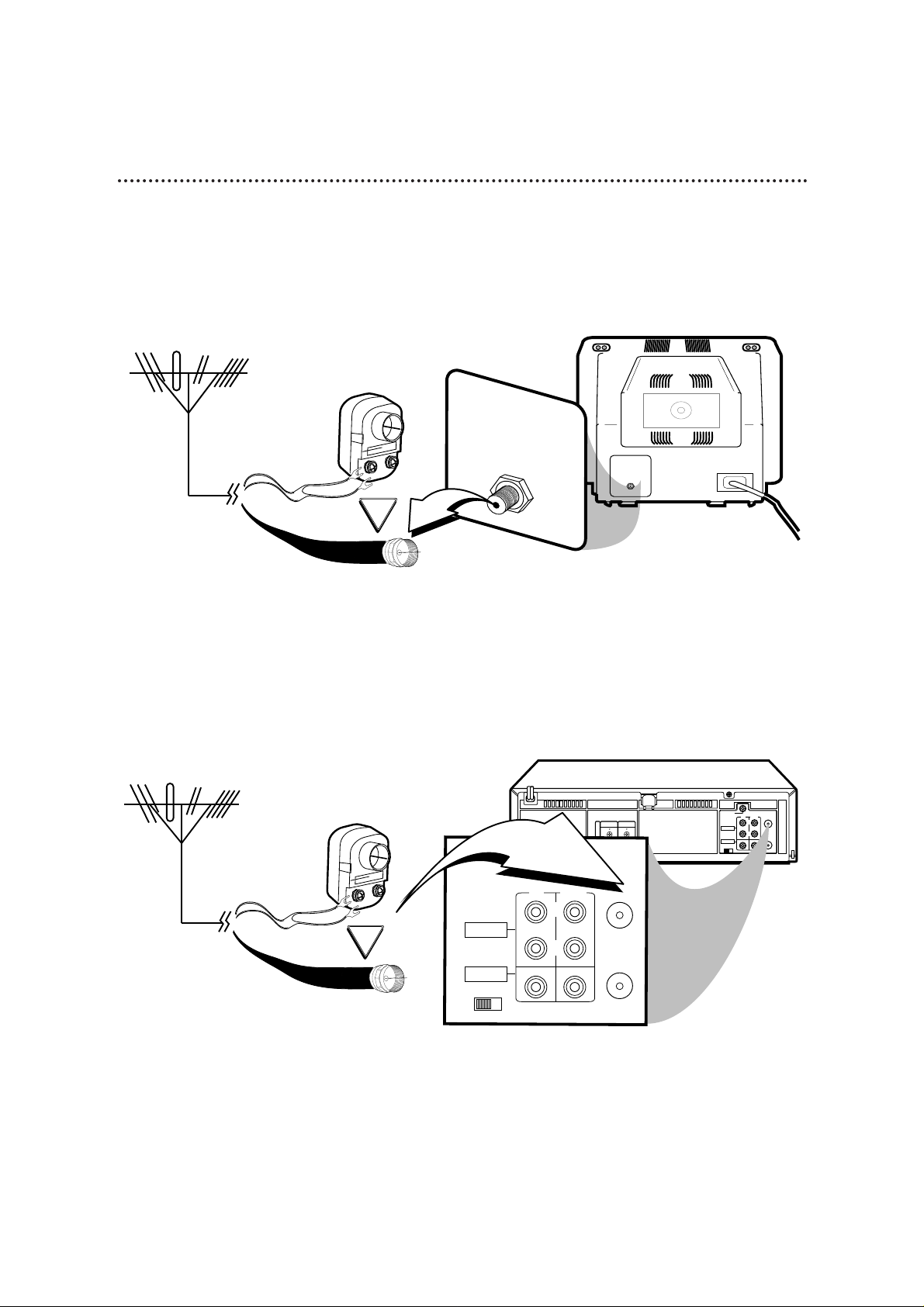
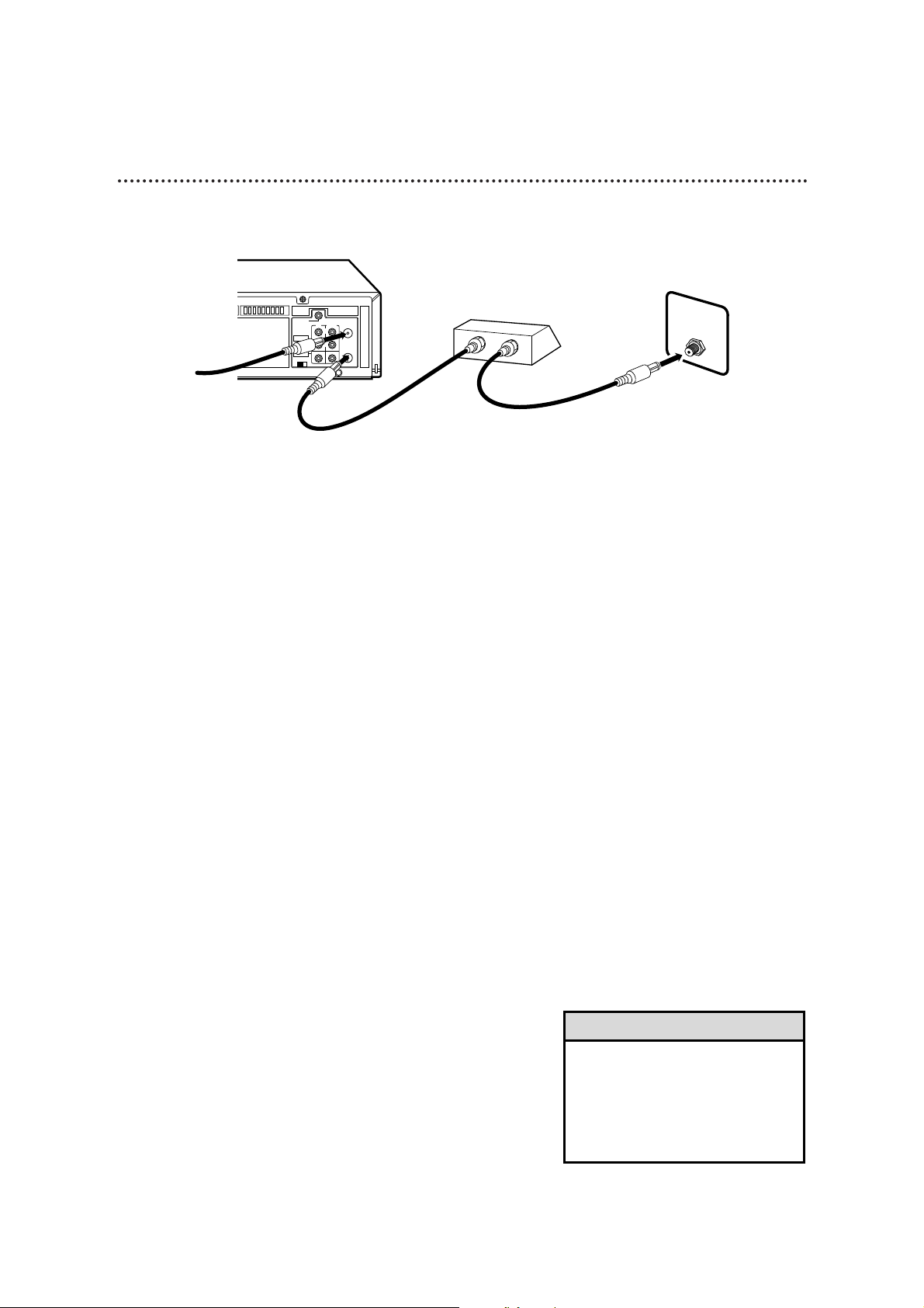
The basic VCR/TV connection – antenna/cable to VCR to TV – is shown below. If you have a Cable Box or
a Direct Broadcast System, please refer to pages 8-9. After you hook up the VCR, please go to pages 10-11
to turn on the VCR.
ANTENNA IN
Jack
(on back of TV)
Cable
(75 ohm)
Antenna
Indoor/Outdoor
(300 ohm)
1
Disconnect the antenna or cable from your TV.
2
Connect the antenna or cable to the ANT(enna) IN Jack on the back of the
VCR.
Cable
(75 ohm)
Antenna
Indoor/Outdoor
(300 ohm)
Page 3
Hookups without a Cable Box (cont’d) 7
CH3 CH4
RF OUT
ANT.IN
AUDIO
VIDEO
IN OUT
IN OUT
R
L
CABLE
BOX
OUT
IN
S
V
I
D
E
O
CH 4
or
CH 3
CH3 / CH4
Switch
CH3 CH4
CH3 CH4
RF OUT
ANT.IN
AUDIO
VIDEO
IN OUT
IN OUT
R
L
CABLE
BOX
CH3 CH4
RF OUT
ANT.IN
AUDIO
VIDEO
IN OUT
IN OUT
R
L
CABLE
BOX
OUT
IN
S
V
I
D
E
O
CH3 CH4
RF OUT
ANT.IN
AUDIO
VIDEO
IN OUT
IN OUT
R
L
75V
ANT /
CABLE
75V
ANT /
CABLE
CABLE
BOX
RF coaxial cable
Antenna
or Cable
3
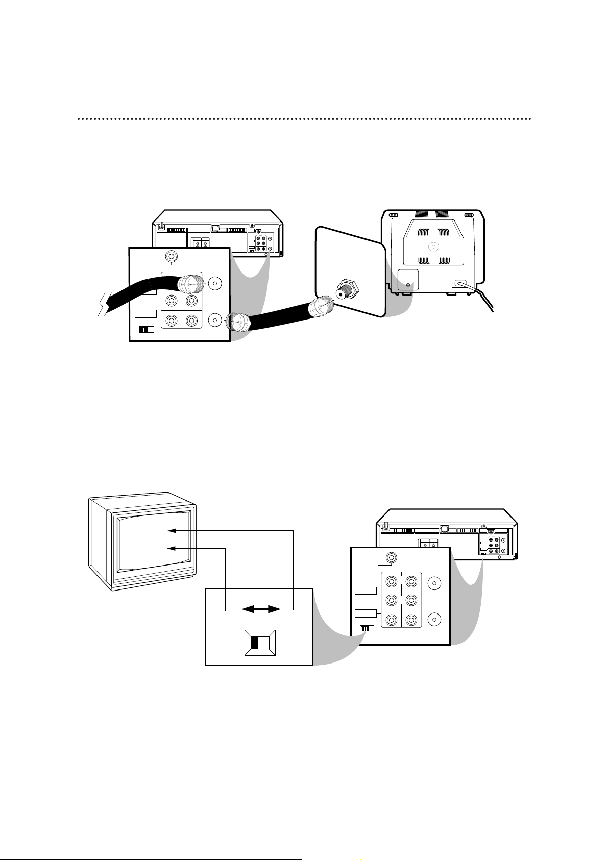
Connect the RF coaxial cable (supplied) to the RF OUT Jack on the back of
the VCR and to the ANTENNA IN Jack on the TV. (You may use either a snap-on
type or screw-on type of coaxial cable, whichever you prefer. A snap-on type is
supplied.)
5
Set the CH3/CH4 switch on the back of the VCR to CH3 or CH4, whichever
channel is not used or least used in your area. To operate your VCR with your TV, set
the TV to the same channel. For example, when playing a tape, if the CH3/CH4
switch is set to CH3, the TV should be on channel 3.
Antenna In Jack
(on back of TV)
example only
4
Plug in the TV and the VCR.
6
You are ready to turn on the VCR. Please go to pages 10-11 before turning on
the VCR.
Page 4
CH3 CH4
RF OUT
ANT.IN
AUDIO
VIDEO
IN OUT
IN OUT
R
L
CABLE
BOX
OUT
IN
S
V
I
D
E
O
75Ω
ANT /
CABLE
OUT
IN
8 Hookups with a Cable Box/Direct Broadcast System
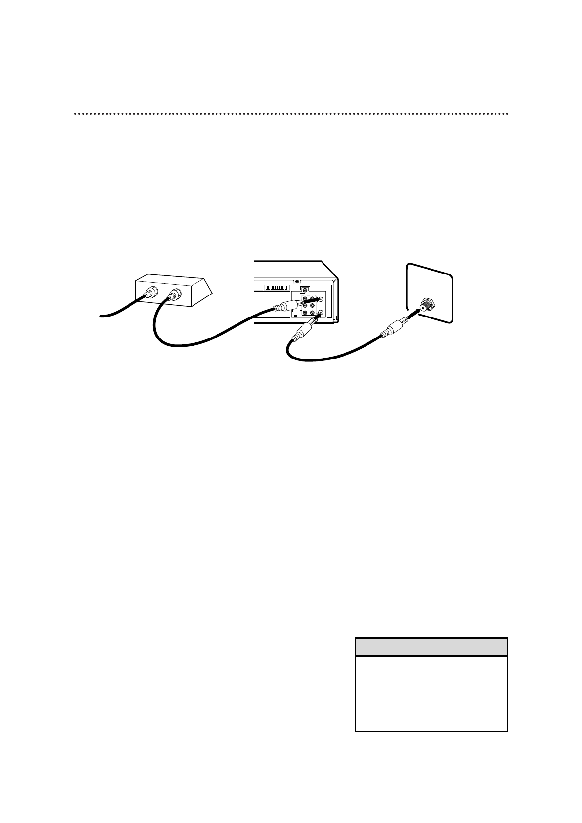
Connections
1
Connect a Cable signal to the IN jack on the Cable Box/DBS.
2
Use an RF coaxial cable (supplied) to connect the OUT jack on the
Cable Box/DBS to the ANT(enna) IN jack on the VCR.
3
Use a second RF coaxial cable to connect the RF OUT jack on the
VCR to the TV’s ANTENNA INjack.
Recording/Viewing Any Channel
1
With the VCR on and in VCR position (the VCR light will appear
on the display panel), use the CH(annel) 8/9 button to set the
VCR to the Cable Box/DBS output channel (channel 03 or 04).
2
Set the TV to the same channel to which you set the VCR. Set the
CH3/CH4 switch on the VCR to the same channel.
3
Select the channel you want to view/record at the Cable Box/DBS.
1
2
There are two ways to connect your Cable Box/DBS to the VCR. With this connection:
• You may view any channel.
• You must select channels at the Cable Box/DBS. Channels cannot be changed at the VCR.
• You may not view a channel other than the one you are recording.
• You may not set up channels at the VCR.
• You can only program a timer recording for one channel at a time if you are not using the Controller.
Set the TV and the VCR to the Cable Box/DBS output channel (channel 03 or 04); set the CH3/CH4
switch to the same channel. Set your Cable Box/DBS to the channel you want to record. When you
enter the channel you want to record in a timer recording, select channel 03 or 04 (the Cable Box/DBS
output channel). (This is step 3 on page 40.) Leave the Cable Box/DBS on for a timer recording.
• To set up the Controller, see pages 49-53.
3
Cable signal
RF coaxial cable
RF coaxial cable
Cable Box/DBS
VCR
TV’s
ANTENNA
IN jack
• If you are using Record Link, use
audio and video cables to connect
the AUDIO/VIDEO OUT jacks on
the Cable Box/DBS to the
AUDIO/VIDEO IN jacks on the back
of the VCR. Details are on page 35.
Helpful Hint
Page 5
Hookups with a Cable Box/Direct Broadcast System (cont’d) 9
CH3 CH4
RF OUT
ANT.IN
AUDIO
VIDEO
IN OUT
IN OUT
R
L
CABLE
BOX
OUT
IN
S
V
I
D
E
O
IN
OUT
75Ω
ANT /
CABLE
Connections
1
Connect a Cable signal to the VCR’s ANT(enna) IN jack.
2
Use an RF coaxial cable (supplied) to connect the RF OUT jack on
the VCR to the IN jack on the Cable Box/DBS.
3
Use a second RF coaxial cable to connect the OUT jack on the
Cable Box/DBS to the TV’s ANTENNA INjack.
Recording One Channel/Watching Another
1
Put the Cable Box/DBS on the same channel as the VCR’s
CH3/CH4 switch. Set the TV to the Cable Box/DBS output
channel (03 or 04).
Then, with the VCR in VCR position (the VCR light will appear on
the display panel), use the CH(annel) 8/9 button to select the
channel you want to record at the VCR. Start the recording.
2
Press the VCR/TV button once to put the VCR in TV position.
(The VCR light will disappear.)
3
Select the channel you want to watch at the Cable Box/DBS.
1
2
With this connection:
• You may watch one channel while recording another.
• You may not record scrambled channels.
3
Cable signal
RF coaxial cable
RF coaxial cable
VCR
Cable Box/DBS
TV’s
ANTENNA
IN jack
• When you play a tape, make sure
the Cable Box/DBS is set to the
same channel as the CH3/CH4
switch on the VCR. Set the TV to
the Cable Box/DBS output channel
(03 or 04).
Helpful Hint
Page 6
SUPER VHS ET
CHANNEL
REC / OTR
MENU
POWER
VIDEO L AUDIO R
PLAY
STOP/EJECT
/
STILL / PAUSE S-VHS ET
OK/
STATUS
VR960B 4-HEAD HI-FI STEREO
VIDEO CASSETTE RECORDER
TURBO
DRIVE
TURBO TIME R . SMAR TPICTURE . MULTIBRAND TV CONTRO L
VCR
SP SLP
NORM
-15dB
6
0
4
+8
L
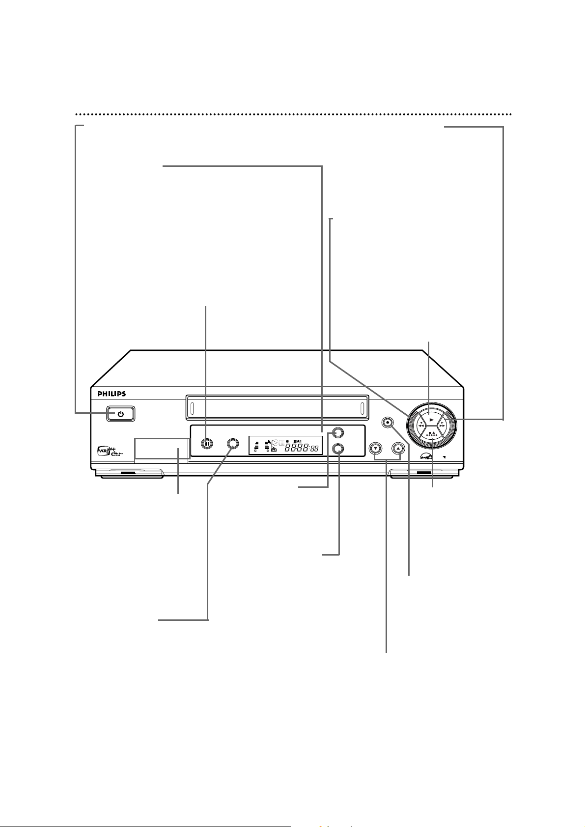
S-VHS ET Button
Press to select S-VHS ET ON
or OFF. S-VHS ET allows
recording with S-VHS picture
quality on VHS cassettes.
Details are on page 32.
22 Front Panel
POWER Button
Press to turn the VCR power on and off.
Remote Sensor
Receives a signal from your remote control so
you can operate your VCR from a distance. Press
the VCR button on the remote control before
pressing other VCR operation buttons.
STILL/PAUSE Button
During tape playback, press once to freeze the
picture. Press repeatedly to advance the Still
picture frame by frame. During tape playback,
press and hold for three seconds to start Slow
Motion playback. Details are on page 61. During
recording, press to temporarily stop the
recording. Details are on page 30.
REC(ord)/OTR Button
Press once to record.
Details are on page 30. Press
repeatedly to start a OneTouch Recording. Details
are on page 34.
CHANNEL 8/9 Buttons
Press to scan through the VCR’s
channels. During tape playback,
press to manually adjust the
tracking. Details are on page 64.
Press to select an item in the
VCR menu.
STOP/EJECT
Button
Press once to stop the
tape. When tape
playback is stopped,
press to eject the tape.
Fast Forward - Button
When tape playback is stopped, press to
fast forward the tape at high speed.
During tape playback, press to fast
forward the tape while the picture stays
on the screen. Details are on page 61.
Press to change the setting of a VCR
menu item.
Rewind / Button
When tape playback is stopped, press to
rewind the tape at high speed. During
tape playback, press to rewind the tape
while the picture stays on the screen.
Details are on page 61.
Press to return to a previous VCR menu.
PLAY Button
Press to play a tape. Press to release
Slow, Still or Search mode and return to
normal playback. Details are on page 61.
Front VIDEO/AUDIO
In Jacks
Connect cables coming from
the VIDEO and AUDIO OUT
Jacks of another VCR or a
camcorder here. Details are on
page 48. To access these jacks,
gently flip down the plastic
cover.
MENU Button
Press to access or
remove the VCR menu.
OK/STATUS Button
Press to go to the next VCR
menu. Press to see the
status display. Details are on
page 26. Press repeatedly to
see the real-time counter,
remaining tape time, the
current channel, or the
current time on the display
panel. Details are on page 21.
Page 7
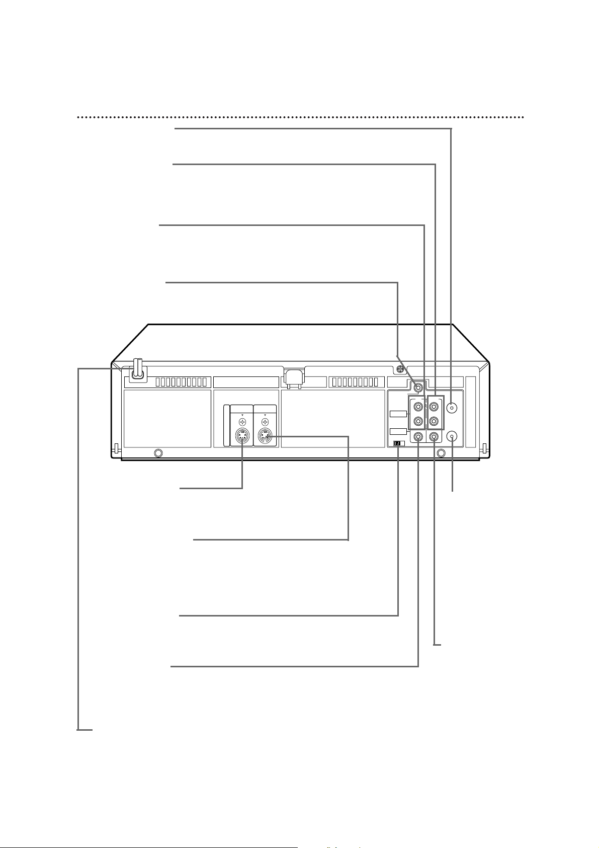
AUDIO OUT Jacks
Connect audio cables going to the AUDIO IN jacks of a
camcorder, another VCR, or an audio system here. Details are on
pages 48 and 55.
AUDIO IN Jacks
Connect audio cables coming from the AUDIO OUT jacks of a
camcorder, another VCR, a Cable Box/DBS, or an audio source
here. Details are on pages 35 and 48.
CABLE BOX Jack
Connect the Controller here. You may use the Controller with
either a Cable Box or DBS receiver. Details are on pages 49-53.
Rear Panel 23
ANT(enna) IN Jack
Connect your antenna or cable here. Details are on pages 6-9.
S-VIDEO IN Jack
Connect an S-Video cable coming from the S-VIDEO OUT
jack of a camcorder or another VCR here.
S-VIDEO OUT Jack
Connect an S-Video cable going to the S-VIDEO In jack of a
TV here. You may use S-Video connections instead of the
standard RCA-style video (yellow) connections. S-Video
connections provide a better picture.
CH3/CH4 Switch
Set to channel 3 or 4 to use your TV with your VCR. Set your
TV to the same channel. Details are on pages 7-9.
VIDEO IN Jack
Connect a video cable coming from the VIDEO OUT jack of a
camcorder, a Cable Box/DBS, or another VCR here. Details
are on pages 35 and 48.
AC Power Cord
Connect to a wall outlet (120 V) to supply power to the VCR.
RF OUT Jack
Use the supplied RF
coaxial cable to
connect this jack to
the ANTENNA IN
Jack on your TV or to
the IN Jack on your
Cable Box/DBS (if
applicable). Details are
on pages 7-9.
CH3 CH4
RF OUT
ANT.IN
AUDIO
VIDEO
IN OUT
IN OUT
R
L
CABLE
BOX
OUT
IN
S
V
I
D
E
O
VIDEO OUT Jack
Connect a video cable
going to the VIDEO
IN jack of a
camcorder or another
VCR here. Details are
on pages 48 and 55.
Page 8
6
Press the PLAY button on VCR 1 and the REC(ord)/OTR
button on VCR 2 at the same time. The \light will appear
on the VCR 2 display panel.
• Unauthorized recording of
copyrighted television programs,
video tapes, or other materials may
infringe on the rights of copyright
owners and violate copyright laws.
• If a program has copyright
protection, it may not record clearly.
• Audio and video cables are not
included.
• To stop copying tapes, press the
STOP/EJECT button on VCR 2, then
press the STOP/EJECT button on
VCR 1.
• If you connect the audio and video
cables to the AUDIO/VIDEO In jacks
on the front of VCR 2, you must
select A/V IN FRONT at step 4. If
you connect the audio and video or
S-Video cables to the AUDIO/VIDEO
IN or AUDIO/S-VIDEO IN jacks on
the back of VCR 2, you must select
A/V IN REAR at step 4. Then select
VIDEO or S-VIDEO at REAR A/V
INPUT in the VCR Set Up menu.
Helpful Hints
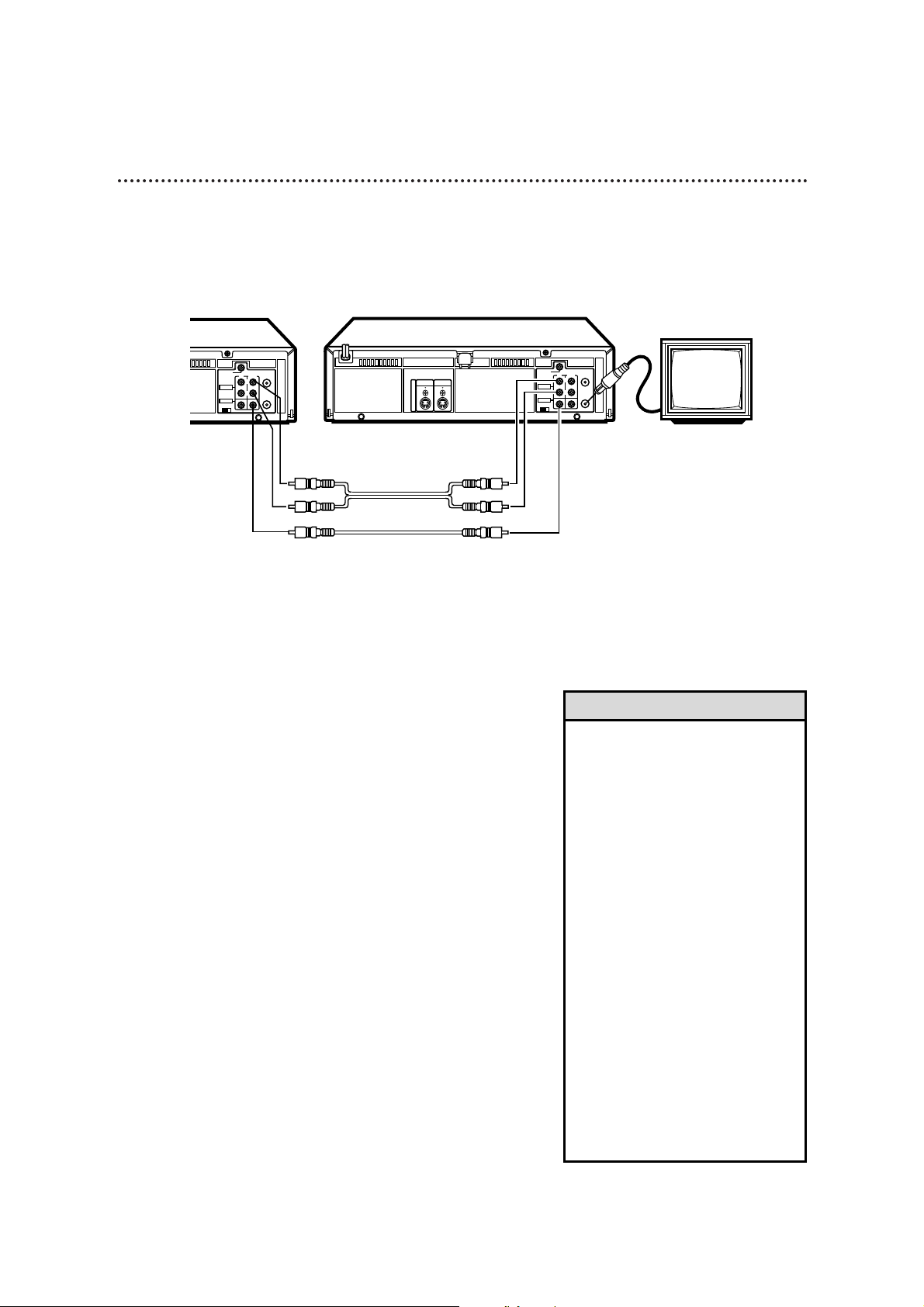
The instructions on this page show you how to copy tapes. Different VCRs may operate differently. To
duplicate a tape, make the connections shown, then follow steps 1-6. (You may use the AUDIO and
VIDEO In jacks on the front of VCR 2 instead if you prefer.)
1
VCR 1 will play your tape. Insert a prerecorded tape in VCR
1. If the tape does not have a record tab, playback begins. If this
happens, press the STOP/EJECT button on VCR 1 once.
2
VCR 2 will record your tape. Insert a blank tape in VCR 2.
Make sure the VCR power is on and the VCR is in VCR
position. (The VCR light will appear on the display panel. If it
does not, press the VCR/TV button once.)
3
Turn on the TV; set it to channel 3 or 4, whichever channel
the CH3/CH4 switch on VCR 2 is set to.
4
Point the remote control at VCR 2. Press the VCR
button, then press the Number buttons 0, 0. Press the
CH(annel) 8/9 button so that A/V IN FRONT or A/V IN REAR
appears on the screen.
5
Point the remote control at VCR 2. Press the
ALT/SPEED button to select SP or SLP.
CH3 CH4
RF OUT
ANT.IN
AUDIO
VIDEO
IN OUT
IN OUT
R
L
CABLE
BOX
OUT
IN
S
V
I
D
E
O
CH3 CH4
RF OUT
ANT.IN
AUDIO
VIDEO
IN OUT
IN OUT
R
L
CABLE
BOX
OUT
1) Use audio cables
to connect the
AUDIO OUT Jacks
on VCR 1 to the
AUDIO IN Jacks on
VCR 2.
VCR 1
Playing VCR
VCR 2
Recording VCR
2) Use a video cable to connect the
VIDEO OUT Jack on VCR 1 to the
VIDEO IN Jack on VCR 2. (Or, to
improve picture quality, you may
connect an S-Video cable to the SVIDEO OUT jack on VCR 1 and to the
S-VIDEO IN jack on VCR 2 instead.)
3) Use an RF coaxial cable to connect the RF OUT
Jack on VCR 2 to the TV’s ANTENNA IN Jack.
audio cables
video cable
48 Rerecording (Tape Duplication)
Page 9
Connecting the Controller 49
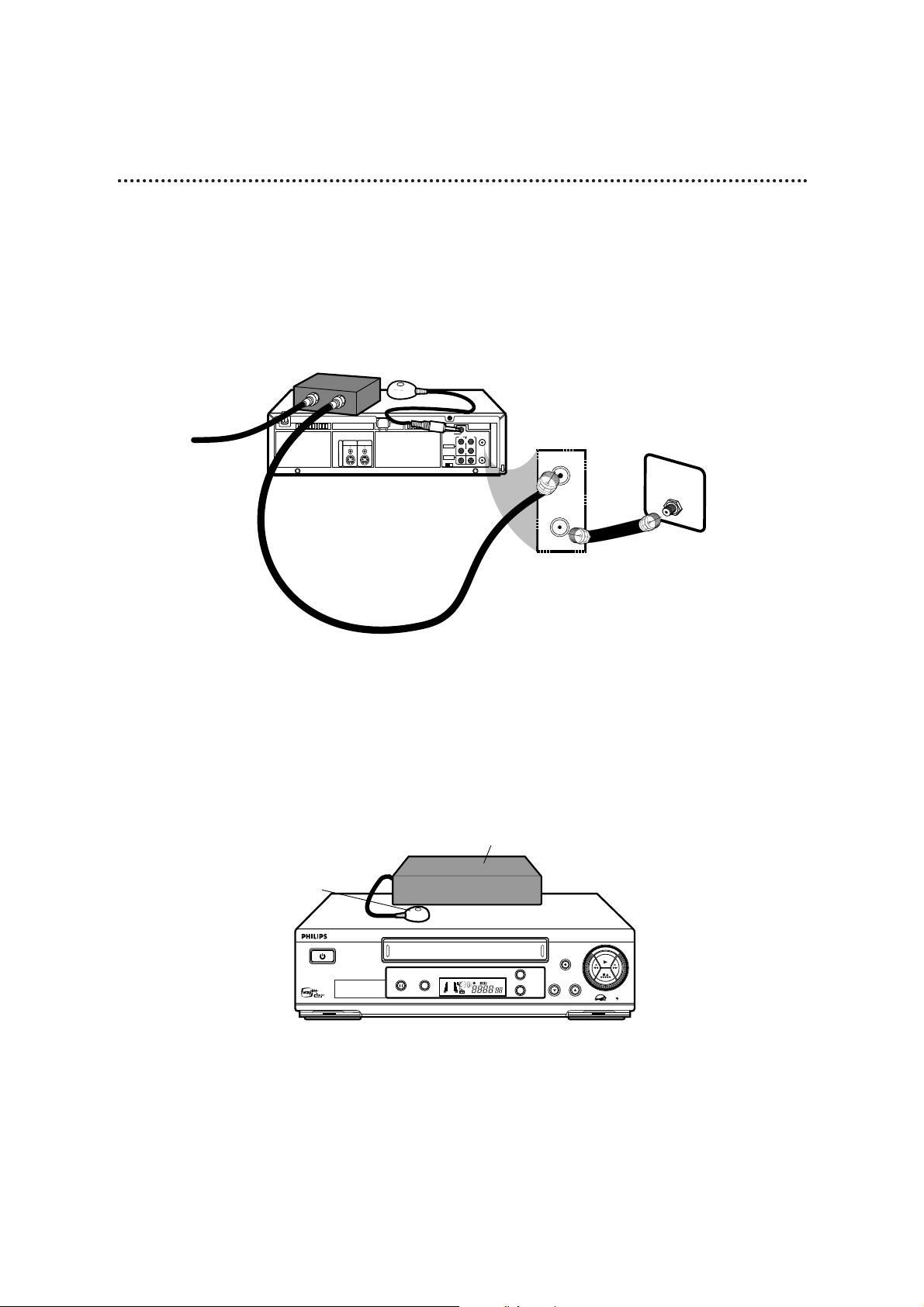
If you are using a Cable Box/DBS, connect the Controller to your VCR. The Controller will automatically
select channels at the Cable Box/DBS during a timer recording. Leave your Cable Box/DBS turned on
during a timer recording.
2
Connect the Controller to the CABLE BOX Jack on the back of the VCR as shown above.
3
Attach the Controller to the top of the VCR using the supplied adhesive. Make sure the
Controller’s transmitter (the light on the top of the Controller) is pointed toward the Cable Box/DBS
remote sensor.
4
If you are using a Cable Box, follow the steps on pages 50-51 to make the Controller change
channels at the Cable Box during timer recordings.
If you are using a DBS, follow the steps on pages 52-53 to make the Controller change
channels at the DBS during timer recordings.
1
Connect the Cable Box/DBS to the VCR as shown below. For more information, please read page
8. Or, refer to the owner’s manual of your Cable Box/DBS.
SUPER VHS ET
CHANNEL
REC / OTR
MENU
POWER
VIDEO L AUDIO R
PLAY
STOP/EJECT
/
STILL / PAUSE S-VHS ET
OK/
STATUS
VR960B 4-HEAD HI-FI STEREO
VIDEO CASSETTE RECORDER
TURBO
DRIVE
TURBO TIMER . SMARTPICTURE . MULTIBRAND TV CON TROL
VCR
SP SLP
NORM
-15dB
6
0
4
+8
L
Connect the Cable
signal to the IN
Jack of the Cable
Box/DBS.
Cable Box/DBS
Controller
Use a second RF coaxial cable to
connect the RF OUT Jack on the
VCR to the TV's ANTENNA IN Jack.
Connect the Controller
to the CABLE BOX Jack
on the back of the VCR.
Use an RF coaxial cable to
connect the OUT Jack on
the Cable Box/DBS to the
ANT(enna) IN Jack on the
back of the VCR.
Cable Box/DBS
Controller
Back of TV (example)
CABLE
IN OUT
IN OUT
ANT.IN
BOX
R
AUDIO
L
RF OUT
VIDEO
CH3 CH4
ANT. IN
RF OUT
75V
ANT /
CABLE
OUT
IN
S
V
I
D
E
O
Page 10
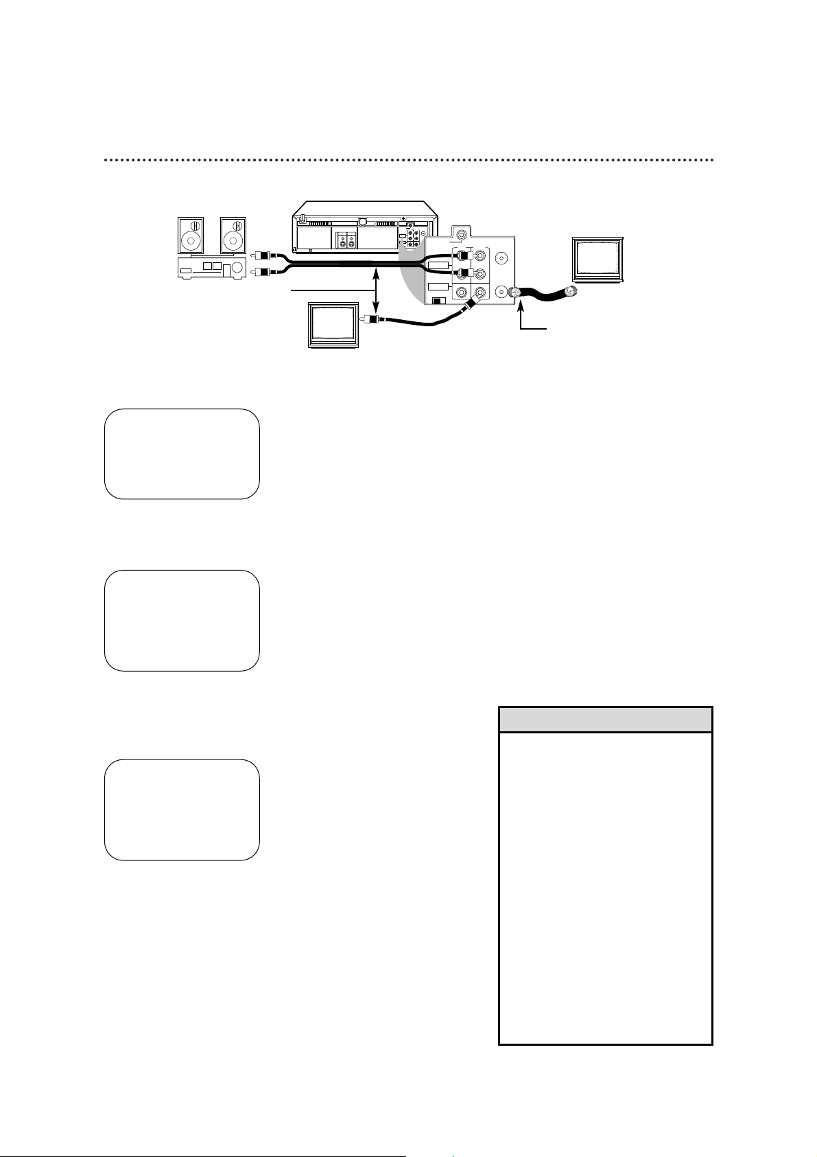
To receive and record programs broadcast in second audio, follow steps 1-6. To receive and record a
program broadcast in stereo, make one of the connections shown, then follow steps 1-6.
6
Record the program as usual. Details are on page 30.
CH3 CH4
RF OUT
ANT.IN
AUDIO
VIDEO
IN OUT
IN OUT
R
L
CABLE
BOX
OUT
IN
S
V
I
D
E
O
CH3 CH4
RF OUT
ANT.IN
AUDIO
VIDEO
OUT
OUT
R
L
IN
CABLE
BOX
1
Press the VCR button, then press the MENU button.
2
Press the PLAY 8 or STOP 9 button to select VCR SET
UP, then press the OK/STATUS button.
3
Press the PLAY 8 or STOP 9 button to select NEXT
PAGE, then press the PLAY 8 or STOP 9 button to select
STEREO/SAP on the second page of the VCR SET UP menu.
4
Press the FF - button to select SAP (for a Second Audio
Program) or STEREO, whichever you prefer.
5
Press the MENU button.
If you have a Stereo and a Monitor TV,
use a video cable to connect the VCR’s
VIDEO OUT Jack to the TV’s VIDEO
IN Jack. Use audio cables to connect
the VCR’s AUDIO OUT Jacks to the
Stereo’s AUDIO IN Jacks.
OR, if you have a single-speaker
TV, use an RF coaxial cable to
connect the VCR’s RF OUT Jack to
the TV’s ANTENNA IN Jack.
• If you want to connect the VCR to a
Stereo TV, follow these steps.
1) Connect the antenna or cable
signal to the VCR’s ANT(enna) IN
jack.
2) Use stereo audio cables to connect
the VCR’s AUDIO OUT jacks to the
TV’s AUDIO IN jacks.
3) Use a video cable to connect the
VCR’s VIDEO OUT jack to the TV’s
VIDEO IN jack. (Or, to improve picture
quality, you may connect an S-Video
cable to the S-VIDEO OUT jack on the
VCR and to the S-VIDEO IN jack on
the TV instead.)
• Make sure the TV and the Stereo (if
applicable) are in Line Input or
Auxiliary mode. Please refer to your TV
or Stereo owner’s manual for details.
Helpful Hints
→ VCR SET UP
TUNER SET UP
INITIAL SET UP
SELECT: ,9 CONFIRM: OK
END: MENU
→ DSPC ON
ON SCREEN MODE ON
BLUE BACKGROUND ON
TIMER REC SPEED MANUAL
VIDEO STABILIZER OFF
AUDIO OUT HIFI
NEXT PAGE
SELECT: ,9 CHANGE: END: MENU
Multi-Channel Television Sound System (cont’d) 55
PREVIOUS PAGE
→ STEREO/SAP SAP
AUTO DBS
RECORD LINK ON
S-VHS MODE ON
REAR A/V INPUT VIDEO
SELECT: ,9 CHANGE: 3
END: MENU
 Loading...