

Page 1
38 EN
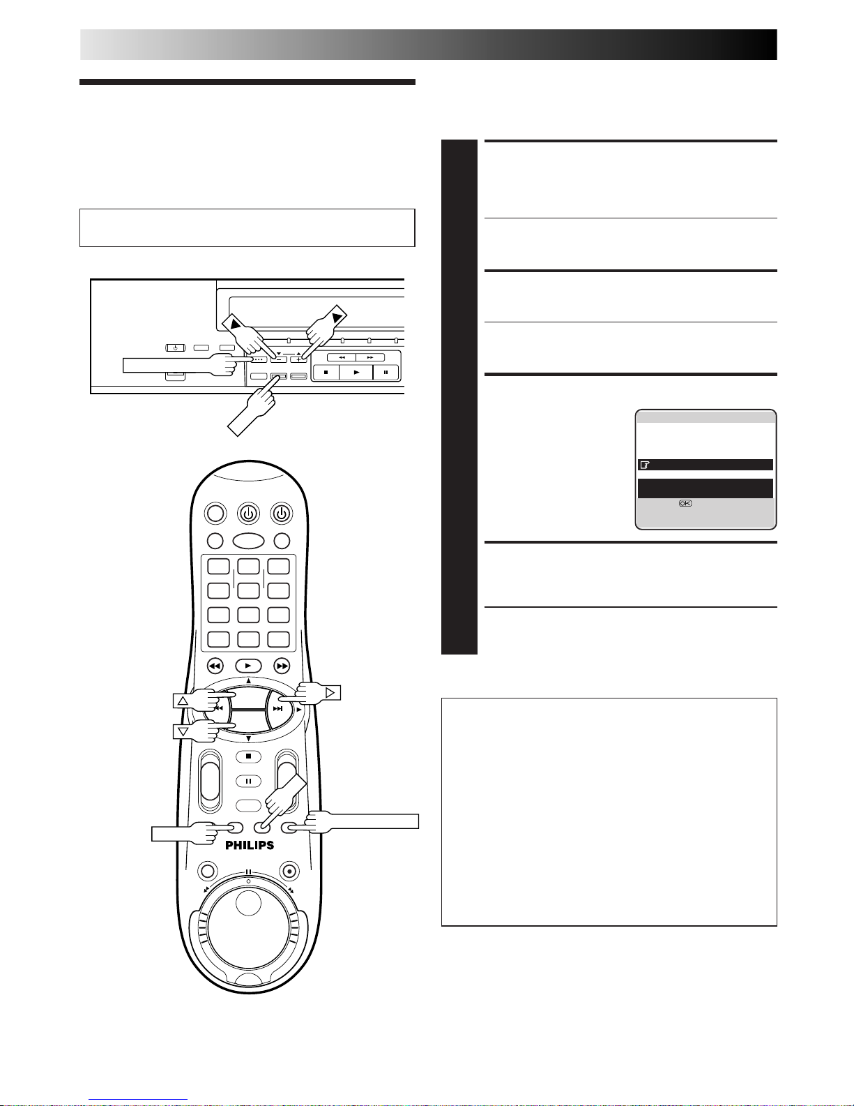
TAPE MANAGER
Tape Manager
Functions
LOAD A RECORDED
CASSETTE
1
Insert a recorded cassette.
● While "– – – –" is blinking on the front display panel,
the tape will run for a few seconds to search for the
tape number.
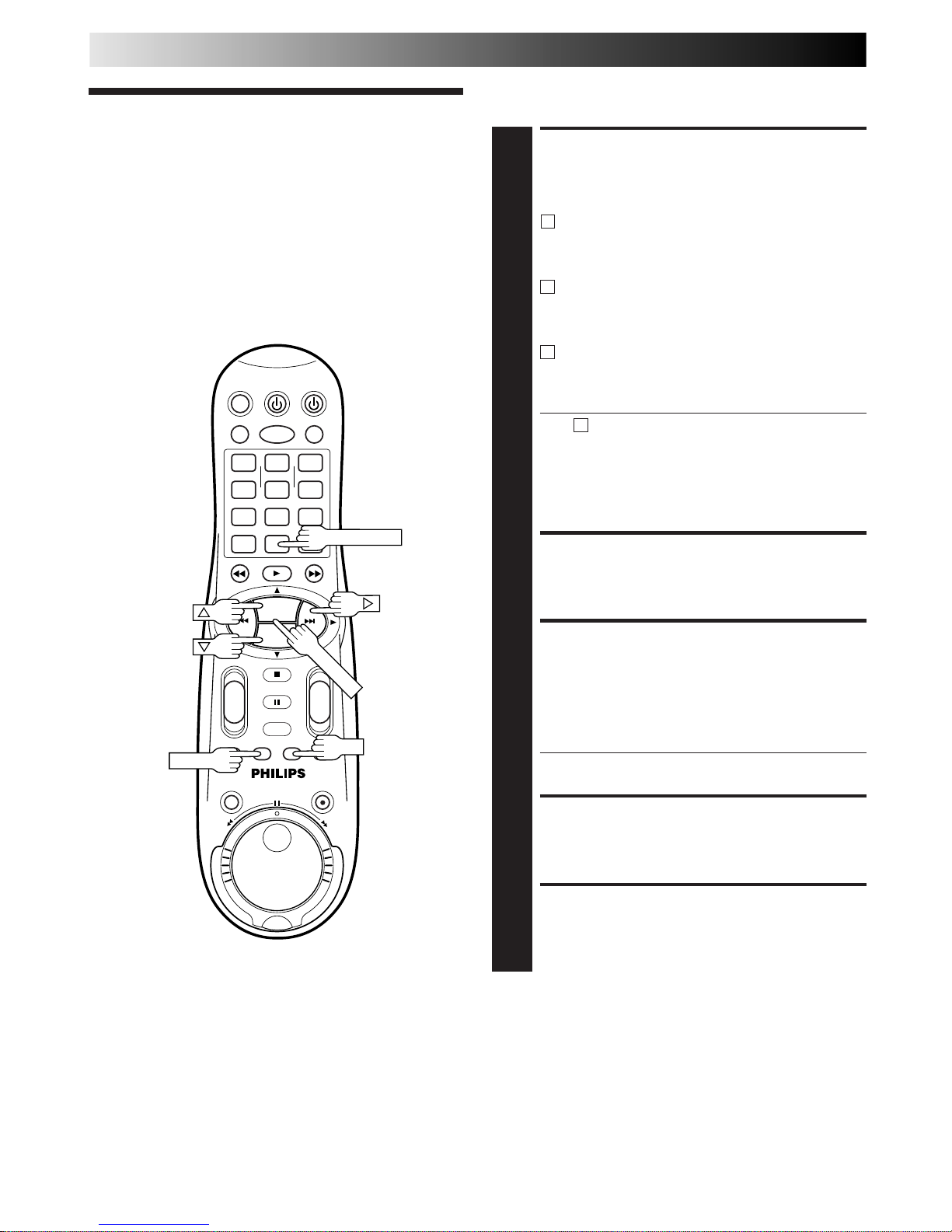
ACCESS TITLE SCREEN
2
Press TAPE MANAGER.
● After pressing TAPE MANAGER, it may take a few
seconds to access the title screen while the recorder
searches for the programme information.
CHOOSE A PROGRAMME
3
Press
%
fi (or
5∞) to
move the highlight bar
(pointer) to the
programme you want to
watch.
START PLAYBACK
4
Press OK. Playback begins automatically after the
selected programme is located.
● If you press # instead of OK, the editing screen will
appear. You can edit the programme title and
category (Z pg. 41).
Turn on the TV and select the AV mode.
This function is useful when you wish to quickly find out what
programmes you have recorded on a tape with this recorder.
This function allows you to select a programme to watch, and
then automatically searches for the start of the programme.
To start recording on the
blank portion of a tape
If you do not record programs consecutively, two tape
numbers will be recorded on one tape and the recorder
will not be able to search for the correct programme. To
continue recording on the blank portion of a tape, follow
the procedure described below:
1 Press %fi, and select a "BLANK" item on the program
title screen.
2 Press OK. The recorder automatically searches for a
blank portion on the tape.
3 After confirming that this is the tape on which you
really wish to record, begin recording.
1
4
2 3
5
8
0
9
6
7
-+-
+
+
+
-
-
PROG. +
PROG. –
OK
MENU
TAPE MANAGER
TAPE MANAGER
TV PROG
OKOKOK
]
0013 FOOTBALL '98 1/ 3
BLANK 1:25 (LS3)
22 : 00 26.02.99 BBC1
20 : 00 27.02.99 BBC2
BLANK 0 : 30 (LS3)
21 : 00 28.02.99 I-1
22 : 15 28.02.99 PR.07
21 : 00=22 : 30 1 : 30 (STD)
WORLD CUP '98 /SPORTS
[
5
∞
] =
[3]
:
EDIT
[TAPE MANAGER]
:
EXIT
Page 2

EN 39
ACCESS MAIN MENU
SCREEN
1
Press MENU.
ACCESS TAPE MANAGER
SCREEN
2
Press
%
fi
to move the
highlight bar (pointer) to
"TAPE MANAGER", then
press OK or #.
CHECK MEMORY
3
Press
%
fi
to move the
highlight bar (pointer) to
"CHECKING MEMORY",
then press OK or #.
● The CHECKING
MEMORY screen will
appear.
RETURN TO NORMAL
SCREEN
4
Press MENU.
Checking Memory
You can check the amount of recorded information in the
memory.
MAIN MENU
MODE SET
AUTO CH SET
MANUAL CH SET
INITIAL SET
TAPE MANAGER
[
5
∞
] =
[MENU] : EXIT
CHECKING MEMORY
0 100
[MENU] : EXIT
TAPE MANAGER
EDITING
SORTING
CHECKING MEMORY
TAPE MANAGER : ON
[5∞] =
[MENU] : EXIT
NOTES:
●
Tape Manager is possible with the cassettes recorded with this
recorder only.
●
To record the date and time as the programme title in this
recorder's memory, make sure the recorder's clock is set
correctly before recording.
●
To record the programme information in this recorder's
memory, you must record each programme for over the
minimum recording time; 10 min. for the D-VHS (STD) mode,
30 min. for the D-VHS (LS3) mode, 8 min. for the S-VHS/VHS
(SP) mode or 15 min. for the S-VHS/VHS (LP) mode.
●
Tape Manager may not work properly depending on the
cassette being used.
●
If the recorder finds two tape numbers in one tape while
playing back or searching for the beginning of a programme,
then when you remove the tape, the tape will be assigned just
one number (smaller number).
●
The programme information is stored in this recorder’s
memory. If the memory in this recorder should ever be
damaged and the programme information lost, it is impossible
to restore that information.
●
After recording a tape with this recorder, write the tape
number on a label and affix the label to the cassette in order
to allow you to find the tape by its number.
TURN OFF TAPE MANAGER
1
Press
%
fi
to move the
highlight bar (pointer) to
"TAPE MANAGER", then
press OK or # to set to
"OFF".
RETURN TO NORMAL
SCREEN
2
Press MENU.
Turn Off Tape Manager
If you don't want to record information on the programmes, set
"TAPE MANAGER" to "OFF".
TAPE MANAGER
EDITING
SORTING
CHECKING MEMORY
TAPE MANAGER : OFF
[5∞] =
[MENU] : EXIT
Perform steps 1 to 2 of "Checking Memory" in the left
column before continuing.
Page 3
40 EN
Title Editing
Turn on the TV and select the AV mode.
When you record a TV programme with this recorder, the
recorder automatically records the recording start time, date,
and channel in each programme title. If the tape is recorded for
the first time, the tape number and the date and time are
recorded in the tape title. You can then edit the tape title and
the programme titles as you like. You can also edit the category
in the programme title.
In short, you can use the Tape Manager function to create your
own video tape library.
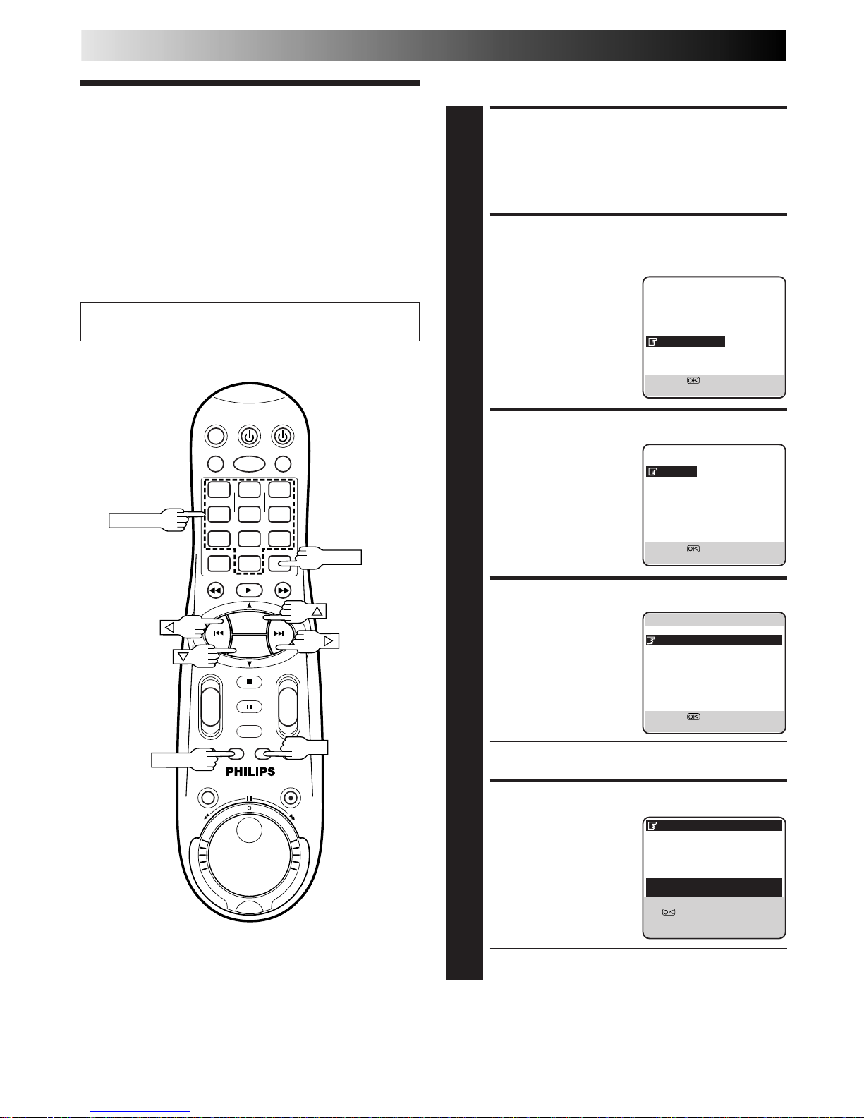
ACCESS MAIN MENU
SCREEN
1
Press MENU.
ACCESS TAPE MANAGER
SCREEN
2
Press
%
fi
to move the
highlight bar (pointer) to
"TAPE MANAGER", then
press OK or #.
ACCESS EDITING SCREEN
3
Press
%
fi
to move the
highlight bar (pointer) to
"EDITING", then press OK
or #.
SELECT TAPE NO.
4
Press
%
fi
to move the
highlight bar (pointer) to
the number of the tape
whose title you want to
edit, then press OK or #.
● The "*" mark indicates the tape number of the
cassette that is currently in the recorder.
SELECT TAPE TITLE
5
Press
%
fi
to move the
highlight bar (pointer) to
the tape number, then
press OK or #.
● The "*" mark indicates the current position on the
tape.
Edit Tape Title
TAPE MANAGER (cont.)
1
4
2 3
5
8
0
9
6
7
-+-
+
+
+
-
-
PROG. +
PROG. –
OK
MENU
NUMBER
CLEAR
MAIN MENU
MODE SET
AUTO CH SET
MANUAL CH SET
INITIAL SET
TAPE MANAGER
[
5
∞
] =
[MENU] : EXIT
TAPE MANAGER
EDITING
SORTING
CHECKING MEMORY
TAPE MANAGER : ON
[5∞] =
[MENU] : EXIT
]
1/ 12
0115 MOVIE1
*
0114 18.03.99 -
0113 25.02.99 0112 23.02.99 0111 MOVIE2
0110 BASEBALL
0108 05.09.98 0107 29.08.98 0106 BEST HIT
[
5
∞
] =
[MENU]
:
EXIT
]
0114 18.03.99 - 1/ 3
20:00 27.02.99 BBC2
22:00 26.02.99 BBC1
21:00 28.02.99 I-1
*
22:15 28.02.99 PR.07
8:15 15.01.00 PR.99
[
5
∞
]
=
: EDIT
= [CLEAR] : DELETE
]
[MENU]
:
EXIT
Page 4
EN 41
Edit Programme Title And
Category
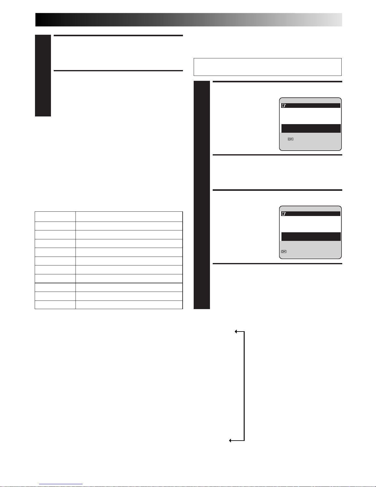
SELECT PROGRAMME
1
Press
%
fi
to move the
highlight bar (pointer) to
the programme you want
to edit, then press OK or #.
ENTER CHARACTER
2
Press NUMBER keys to enter characters, then press OK.
For details, refer to "Entering Character" in the left
column.
SELECT CATEGORY
3
Press
%
fi
to move the
highlight bar (pointer) to
select the category you
want, then press OK or #.
RETURN TO NORMAL
SCREEN
4
Press MENU.
Perform steps 1 to 4 of "Edit Tape Title" on page 40 before
continuing.
ENTER CHARACTER
6
Press NUMBER keys to enter characters, then press OK.
For details, refer to "Entering Character" below.
RETURN TO NORMAL
SCREEN
7
Press MENU.
]
0114 18.03.99 - 1/ 3
20:00 27.02.99 BBC2
22:00 26.02.99 BBC1
21:00 28.02.99 I-1
*
22:15 28.02.99 PR.07
8:15 15.01.00 PR.99
20:00=21:30 1:30 (STD)
TITLE /CATEGORY
[
5
∞
]
=
: EDIT
= [CLEAR] : DELETE
[MENU]
:
EXIT
]
0114 18.03.99 - 1/ 3
20:00 27.02.99 BBC2
22:00 26.02.99 BBC1
21:00 28.02.99 I-1
*
22:15 28.02.99 PR.07
8:15 15.01.00 PR.99
20:00=21:30 1:30 (STD)
WORLD CUP '98 /SPORTS
[
5
∞
]: SELECT
: OK
[MENU]
:
EXIT
Entering Character
Press NUMBER key, then press # to enter each character.
Refer to the example below.
(Ex.) Enter "NEWS"
1 Press 6 (MNO) twice to enter "N", then press
#
.
2 Press 3 (DEF) twice to enter "E", then press
#
.
3 Press 9 (WXYZ) once to enter "W", then press
#
.
4 Press 7 (PQRS) four times to enter "S", then press
#
.
NOTES:
●
If you make a mistake, press
@ #
to select the character, then
enter the correct character.
●
If you want to delete a character, press
@ #
to select the
character, then press CLEAR.
Choice Of Category
CATEGORY
%
%
fi
MOVIE
%
fi
SPORTS
%
fi
SPECIAL
%
fi
SERIES
%
fi
SHOW
%
fi
MUSIC
%
fi
CHILDREN
%
fi
NEWS
%
fi
OTHERS
fi
NUMBER KEY CHARACTER
1 . , / – + * ( ) 1
2 A B C 2 Ä À Á Â Ã Å Æ
3 D E F 3 È É Ë Ê
4 G H I 4 Î Ï Ì Í
5 J K L 5
6 M N O 6 Ö Ô Ò Ó Õ Ø Ñ
7 P Q R S 7
8 T U V 8 Ü Ù Û Ú
9 W X Y Z 9
0 0
_
Page 5
42 EN
TAPE MANAGER (cont.)
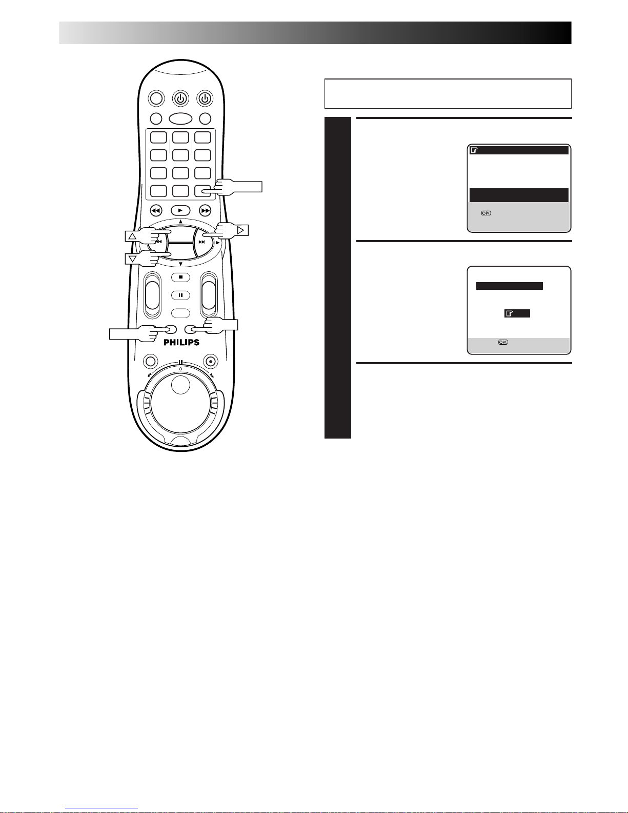
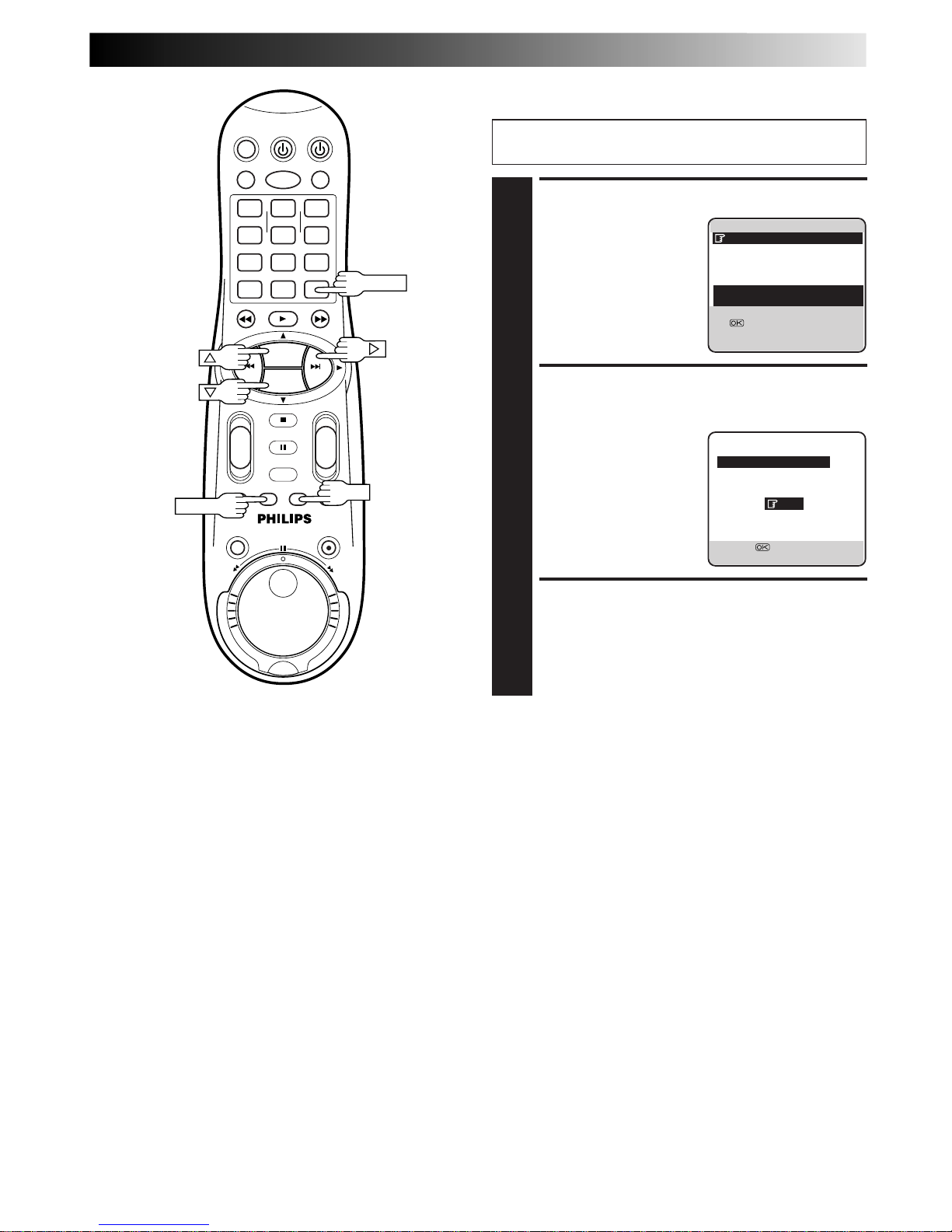
Delete Tape Data
SELECT TAPE TITLE
1
Press
%
fi
to move the
highlight bar (pointer) to
the tape number you want
to delete, then press
CLEAR.
DELETE TAPE DATA
2
Press
%
fi
to move the
highlight bar (pointer) to
"YES", then press OK or #.
RETURN TO NORMAL
SCREEN
3
Press MENU.
Perform steps 1 to 4 of "Edit Tape Title" on page 40 before
continuing.
]
0114 18.03.99 - 1/ 3
20:00 27.02.99 BBC2
22:00 26.02.99 BBC1
21:00 28.02.99 I-1
*
22:15 28.02.99 PR.07
8:15 15.01.00 PR.99
[
5
∞
]
=
: EDIT
= [CLEAR] : DELETE
]
[MENU]
:
EXIT
]
0114 18.03.99 -
DELETE
YES
NO
[
5
∞
] =
[MENU]
:
EXIT
1
4
2 3
5
8
0
9
6
7
-+-
+
+
+
-
-
PROG. +
PROG. –
OK
MENU
CLEAR
Page 6
EN 43
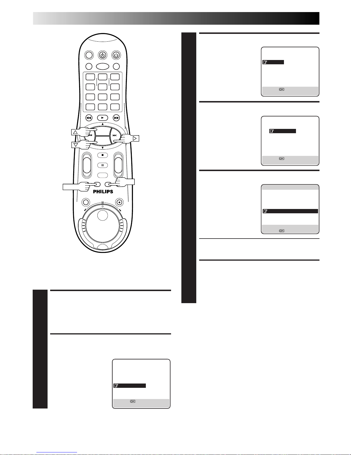
Delete Programme Data
SELECT PROGRAMME
1
Press
%
fi
to move the
highlight bar (pointer) to
the programme you want
to delete, then press
CLEAR.
DELETE PROGRAMME
DATA
2
Press
%
fi
to move the
highlight bar (pointer) to
"YES", then press OK or #.
RETURN TO NORMAL
SCREEN
3
Press MENU.
Perform steps 1 to 4 of "Edit Tape Title" on page 40 before
continuing.
NOTES:
●
When you delete data, only the tape and/or programme
information is deleted. The actual recording on the tape is not
erased.
●
If the recorder’s memory becomes full, the recorder registers
the tape in the library under the smallest tape number that is
still available.
]
0114 18.03.99 - 1/ 3
20:00 27.02.99 BBC2
22:00 26.02.99 BBC1
21:00 28.02.99 I-1
*
22:15 28.02.99 PR.07
8:15 15.01.00 PR.99
20:00=21:30 1:30 (STD)
TITLE /CATEGORY
[
5
∞
]
=
: EDIT
= [CLEAR] : DELETE
[MENU]
:
EXIT
20:00 27.02.99 BBC2
DELETE
YES
NO
[
5
∞
] =
[MENU]
:
EXIT
1
4
2 3
5
8
0
9
6
7
-
+-+
+
+
-
-
PROG. +
PROG. –
OK
MENU
CLEAR
Page 7
44 EN
TAPE MANAGER (cont.)
Sorting By Tape Number
If you have recorded a lot of tapes with this recorder, this
function is useful for finding out what is recorded on each tape.
1
4
2 3
5
8
0
9
6
7
-+-
+
+
+
-
-
PROG. +
PROG. –
OK
MENU
MAIN MENU
MODE SET
AUTO CH SET
MANUAL CH SET
INITIAL SET
TAPE MANAGER
[
5
∞
] =
[MENU] : EXIT
TAPE MANAGER
EDITING
SORTING
CHECKING MEMORY
TAPE MANAGER : ON
[5∞] =
[MENU] : EXIT
SORTING
BY TAPE NO.
BY DATE
BY CATEGORY
[5∞] =
[MENU] : EXIT
]
1/100
0999 BBC2 1900 28.12.99
0999 F1 BRAZIL 28.12.99
0999 007 GOLDE 25.12.99
0999 BBC1 2100 30.11.99
0998 ZDF 2100 28.11.99
0998 PR99 1000 01.01.00
0997 ARSENAL V 25.11.99
0996 BBC2 2300 24.11.99
0996 RA11 915 26.12.99
[
2 3
]
:
PAGE [MEMU] : EXIT
[
5
∞
] = : EDIT
ACCESS SORTING SCREEN
3
Press
%
fi
to move the
highlight bar (pointer) to
"SORTING", then press OK
or #.
ACCESS TAPE NO. SCREEN
4
Press
%
fi
to move the
highlight bar (pointer) to
"BY TAPE NO.", then press
OK or #.
SELECT TAPE NO.
5
Press
%
fi
to move the
highlight bar (pointer) to
the tape number you want
to select, then press OK.
● The editing screen will appear. You can edit the tape
title, or the programme title and category (Z pg. 40,
41).
RETURN TO NORMAL
SCREEN
6
Press MENU.
NOTE:
If you wish to play back the programme on the tape you have
found, insert the cassette and see the "Tape Manager Functions"
(Z pg. 38) for the operation.
ACCESS MAIN MENU
SCREEN
1
Press MENU.
ACCESS TAPE MANAGER
SCREEN
2
Press
%
fi
to move the
highlight bar (pointer) to
"TAPE MANAGER", then
press OK or #.
Page 8
EN 45
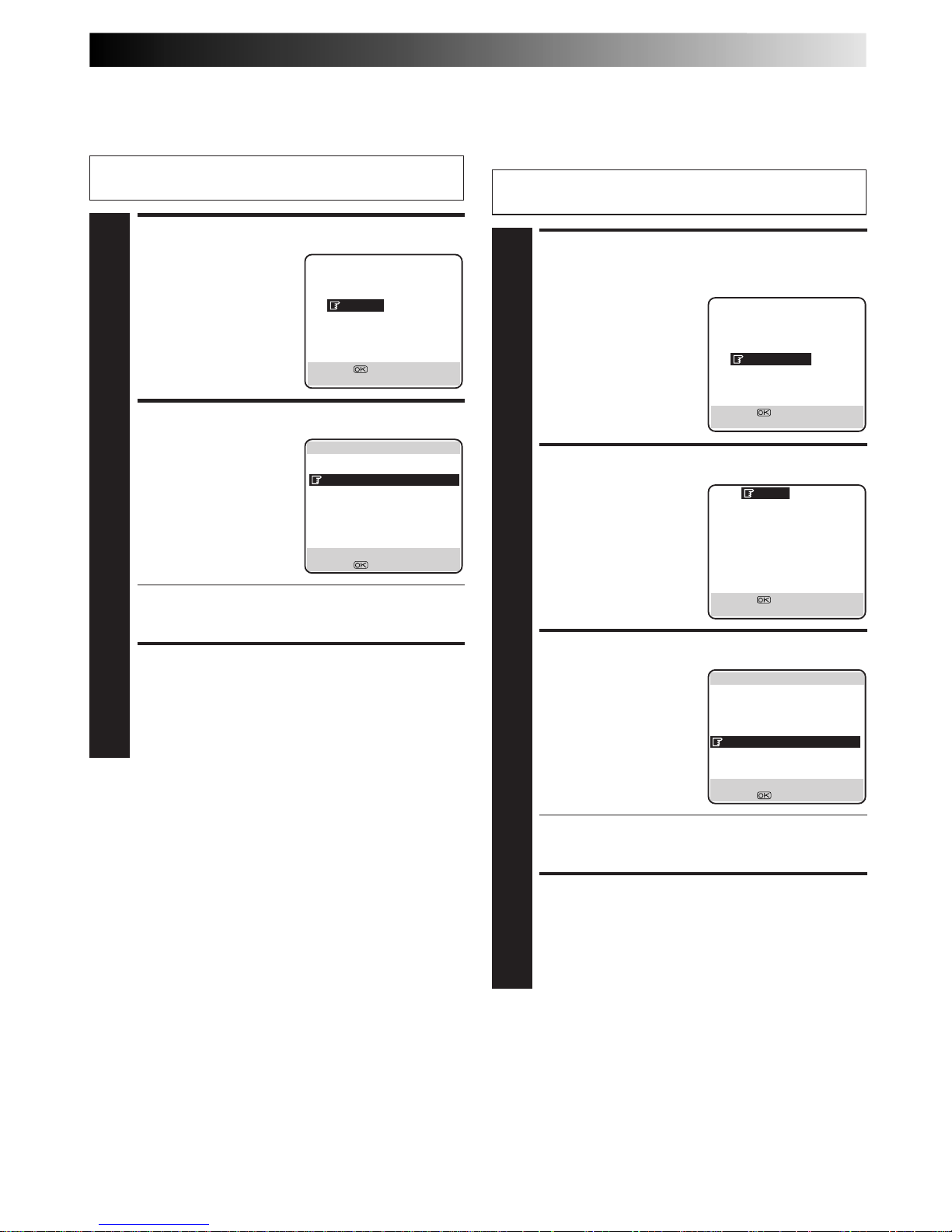
ACCESS CATEGORY
SCREEN
1
Press
%
fi
to move the
highlight bar (pointer) to
"BY CATEGORY", then
press OK or #.
SELECT CATEGORY
2
Press
%
fi
to move the
highlight bar (pointer) to
the category you want to
watch, then press OK or #.
SELECT TAPE NO.
3
Press
%
fi
to move the
highlight bar (pointer) to
the tape number you want
to select, then press OK.
● The editing screen will appear. You can edit the tape
title, or the programme title and category (Z pg. 40,
41).
RETURN TO NORMAL
SCREEN
4
Press MENU.
Sorting By Category
If you have recorded a lot of tapes with this recorder, this
function is useful for finding out what category of programme is
recorded on the tape.
Perform steps 1 to 3 of "Sorting By Tape Number" on page
44 before continuing.
SORTING
BY TAPE NO.
BY DATE
BY CATEGORY
[5∞] =
[MENU] : EXIT
MOVIE
SPORTS
SPECIAL
SERIES
SHOW
MUSIC
CHILDREN
NEWS
OTHERS
– – – – – – – –
[5∞] =
[MENU] : EXIT
]
MOVIE 1/ 2
0999 007 GOLDE25.12.99
0980 GUNDAM3 23.12.98
0979 GUNDAM2 21.12.98
0975 GUNDAM1 30.10.99
0960 ZDF 2100 28.11.97
0960 PR99 1000 01.01.00
0951 GODILLA 25.11.97
0926 CNN 115 06.06.98
0910 RA11 930 05.02.99
[
2 3
]
:
PAGE [MEMU] : EXIT
[
5
∞
] = : EDIT
ACCESS DATE SCREEN
1
Press
%
fi
to move the
highlight bar (pointer) to
"BY DATE", then press OK
or #.
SELECT TAPE NO.
2
Press
%
fi
to move the
highlight bar (pointer) to
the tape number you want
to select, then press OK.
● The editing screen will appear. You can edit the tape
title, or the programme title and category (Z pg. 40,
41).
RETURN TO NORMAL
SCREEN
3
Press MENU.
Sorting By Date
If you have recorded a lot of tapes with this recorder, this
function is useful for searching for tape numbers sorted by date.
Perform steps 1 to 3 of "Sorting By Tape Number" on page
44 before continuing.
SORTING
BY TAPE NO.
BY DATE
BY CATEGORY
[5∞] =
[MENU] : EXIT
]
1/100
0997 JAPAN VS 14.02.00
0993 LOST WORL 02.01.00
0998 PR99 1000 01.01.00
0999 FOOTBALL 28.12.99
0999 F1 BRAZIL 28.12.99
0996 RA11 2000 26.12.99
0999 007 GOLDE 25.12.99
0993 CNN 115 25.12.99
0999 BBC1 2000 30.11.99
[
2 3
]
:
PAGE [MEMU] : EXIT
[
5
∞
] = : EDIT
Page 9
46 EN
EDITING
Edit From
A Camcorder
NOTES:
●
All necessary cables can be obtained from your dealer.
●
You can also use another video recorder as the player instead
of a camcorder.
●
When you are editing through the DV IN connector, the
recorder will stop if the player begins playing a blank portion
of tape or the signal is interrupted.
1
4
2 3
5
8
0
9
6
7
-+-
+
+
+
-
-
PROG. +
PROG. –
PROG.+/–
NUMBER "0"
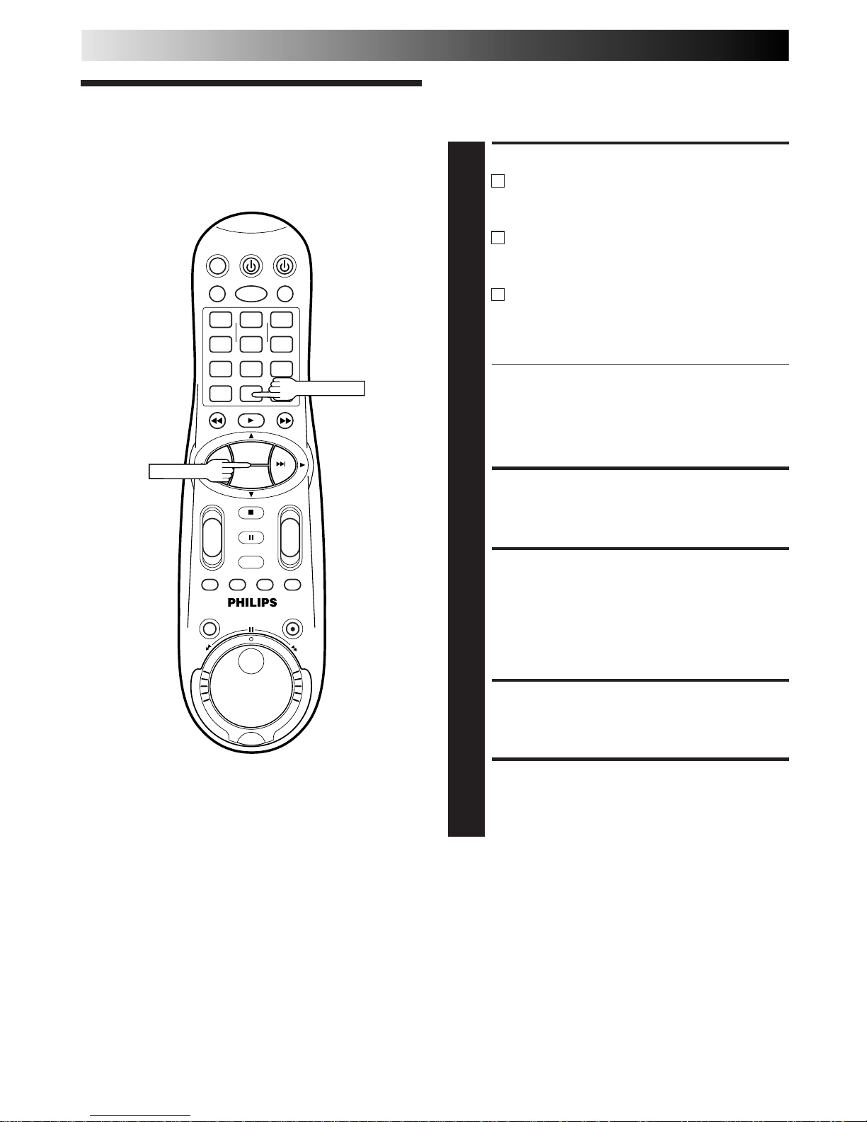
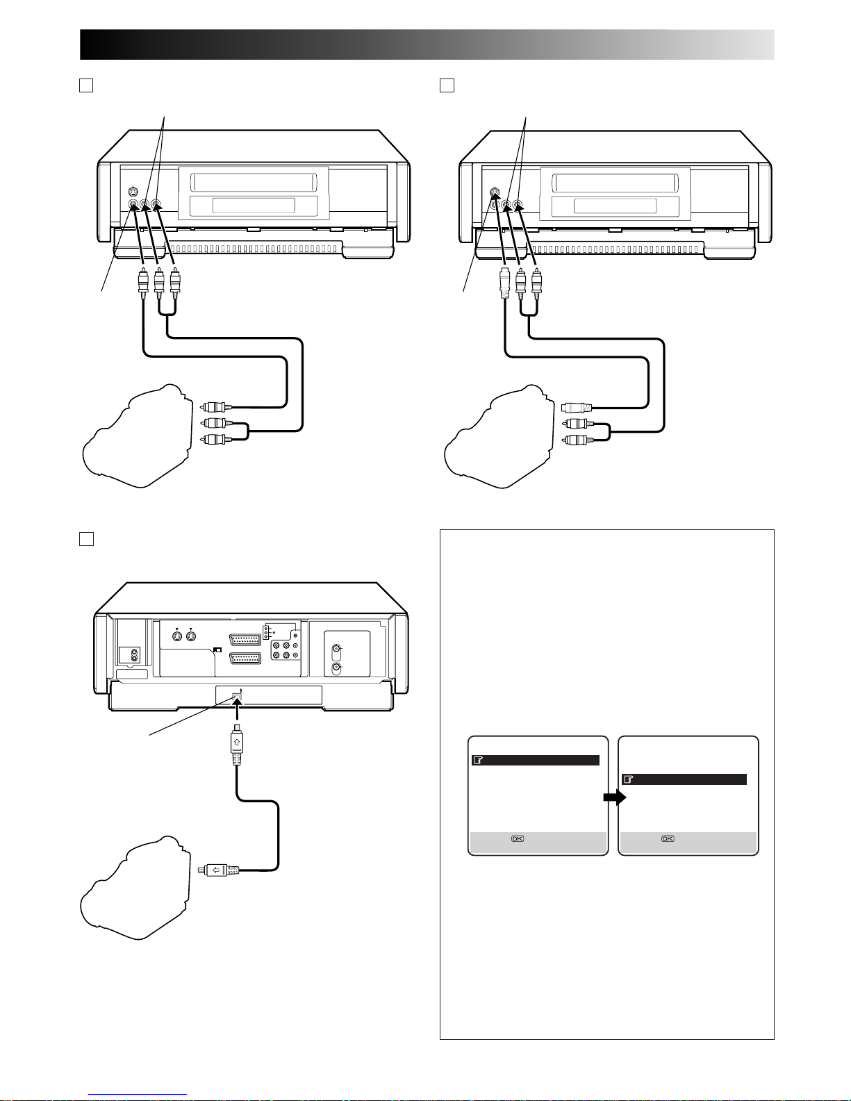
You can use a camcorder as the source player and your video
recorder as the recorder.
You can perform digital editing if the camcorder has a DV
output connector.
MAKE CONNECTIONS
1
A
If the camcorder has no S-VIDEO output connector...
... connect the camcorder’s AUDIO/VIDEO OUT
connectors to the recorder’s front panel AUDIO/
VIDEO input connectors.
B
If the camcorder has an S-VIDEO output connector...
... connect the camcorder’s S-VIDEO OUT and
AUDIO OUT connectors to the recorder’s front
panel S-VIDEO and AUDIO input connectors.
A C
If the camcorder has a DV OUT connector...
... connect the camcorder’s DV OUT connector to
the recorder’s DV IN connector.
See "DV Sound Setting" (Z pg. 47) for the DV
sound selection.
● When using a mono camcorder, connect its AUDIO
OUT connector to the AUDIO L input connector on
your recorder.
● When a certain camcorder with Master Edit Control is
used, the camcorder is capable of controlling the
recorder. Refer to the camcorder’s instruction manual
for operating procedure.
SET RECORDING MODE
2
Set the appropriate recording mode (D-VHS, S-VHS or
VHS) (Z pg. 22, 23).
SET RECORDER’S INPUT
MODE
3
Press NUMBER key "0" and/or PROG. +/– to select
"F-1" for the AUDIO/VIDEO input connectors, "S-2" for
the AUDIO/S-VIDEO input connectors, or "I-1" for the
DV input connectors, depending on the connectors
being used.
START CAMCORDER
4
Engage its Play mode.
START RECORDER
5
Engage its Record mode.
Page 10
EN 47
VIDEO OUT
Camcorder
VIDEO
input
Recorder
AUDIO OUT
Video Cable (not provided)
Player
AUDIO input
A If the camcorder has no S-VIDEO output connector...
S-VIDEO OUT
Camcorder
S-VIDEO
input
Recorder
AUDIO OUT
Audio Cable (not provided)
Player
B If the camcorder has an S-VIDEO output connector...
AUDIO input
S-Video Cable (provided)
Audio Cable (not provided)
DV Camcorder
Recorder
DV OUT
DV Cable
(not provided)
Player
C If the camcorder has a DV OUT connector...
DV IN
DV Sound Setting
Up to four audio signal channels can be input from a DV
camcorder through the DV IN connector (i.Link). This
recorder allows you to select and record two of these
channels. This setting is used to specify which two
channels to record.
1 Press MENU to access the Main Menu screen.
2 Move the highlight bar (pointer) to "MODE SET" by
pressing %fi, then press OK or #.
3 Move the highlight bar (pointer) to "DV SOUND" by
pressing %fi, then press OK or # to select "SOUND1",
"SOUND2" or "FULL".
When there are four DV audio channels (32kHz):
SOUND 1: Records the two channels (L/R) of DV
SOUND 1.
SOUND 2: Records the two channels (L/R) of DV
SOUND 2.
FULL: Mixes and records both DV SOUND 1 and
2.
When there are two DV audio channels (48kHz):
Because there are only two channels, those two
channels are recorded regardless of the DV sound
setting.
4 Press MENU to return to the normal screen.
PREVIOUS PAGE
AV1 SELECT VIDEO
AV2 SELECT AV2
DV SOUND SOUND1
AUDIO REC NICAM
[5∞] =
[MENU] : EXIT
MODE SET
DSPC ON
O. S. D. ON
DIRECT RECORD ON
AUTO SP=LP TIMER OFF
DIGITAL 3R ON
POWER SAVE OFF
S-VHS AUTO
NEXT PAGE
[5∞] =
[MENU] : EXIT
Page 11
48 EN
Edit To Or
From Another
Video
Recorder
You can use your video recorder as the source player or as the
recording deck.
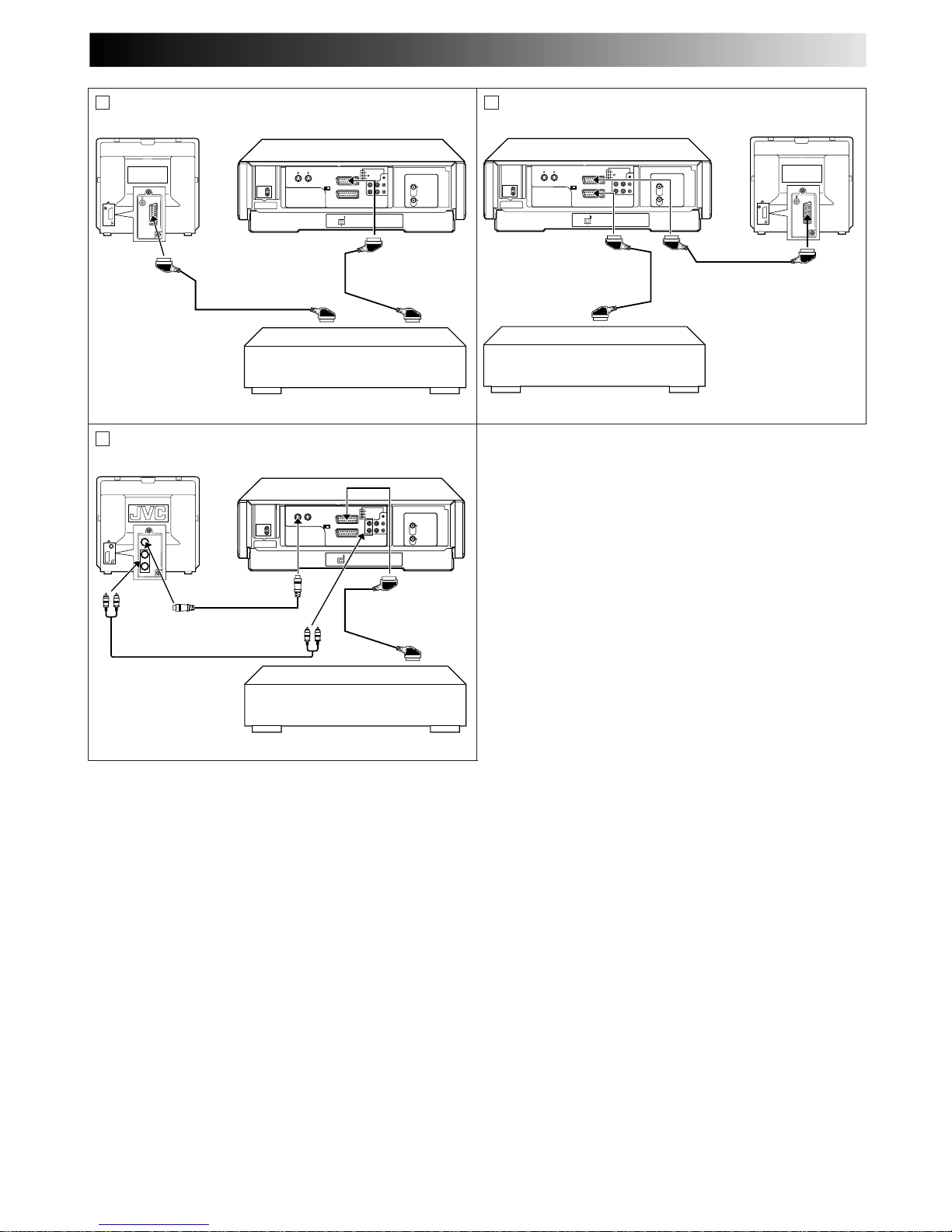
MAKE CONNECTIONS
1
Connect the player’s 21-pin SCART connector to the
recorder’s 21-pin SCART connector as illustrated on
page 49.
A
When Using Your Video Recorder As The Source
Player ...
... connect its AV1 IN/OUT connector to the
recording deck.
BWhen Using Your Video Recorder As The Recording
Deck ...
... connect its AV2 IN/DECODER or AV1 IN/OUT
connector to the source player.
CIf Another Recorder Is Compatible With The Y/C
Signal ...
... connect your recorder's AV1 IN/OUT connector to
another recorder.
With C connection ...
● When using your recorder as the recording deck, set
"AV1 SELECT" to "S-VIDEO" and "AV2 SELECT" to
"AV2" (Z pg. 50).
● When using your recorder as the source player, set
the AV1 OUT switch on the rear panel to Y/C
(Z pg. 6).
SET RECORDING MODE
2
Set the appropriate recording mode (D-VHS, S-VHS or
VHS) (Z pg. 22, 23).
SET RECORDING DECK’S
INPUT MODE
3
Set to AUX. With this video recorder, press NUMBER
key "0" and/or PROG. +/– to select "L-1" for the AV1 IN/
OUT connector, or "L-2" for the AV2 IN/DECODER
connector, depending on the connector being used.
● When using the AV2 IN/DECODER connector, make
sure "AV2 SELECT" is set to "AV2" (Z pg. 50).
START SOURCE PLAYER
4
Engage its Play mode.
START RECORDING DECK
5
Engage its Record mode.
EDITING (cont.)
1
4
2 3
5
8
0
9
6
7
-+-
+
+
+
-
-
PROG. +
PROG. –
OK
MENU
NUMBER "0"
PROG.+/–
Page 12
EN 49
NOTES:
●
All necessary cables can be obtained from your dealer.
●
For Y/C signal input/output, be sure to use a 21-pin SCART cable that is compatible with the Y/C signal.
●
When you use this recorder as the player for editing, be sure to set "O.S.D." to "OFF" before starting (Z pg. 12).
●
If you are using another recorder with S-Video and Audio input/output connectors, you can connect those connectors to this
recorder's S-VIDEO and AUDIO input/output connectors.
When Using Your Video Recorder As The Source Player ...
... connect its rear panel S-VIDEO and AUDIO output connectors to the recording deck's S-Video and Audio input connectors.
When Using Your Video Recorder As The Recording Deck ...
... connect its rear panel S-VIDEO and AUDIO input connectors to the source player's S-Video and Audio output connectors.
Then, set the recorder's input mode to "S-1".
Another recorder
Another recorder
Recorder
21-pin SCART
Cable (provided)
Player Your recorder
Recorder Your recorder
TV Receiver
(AV mode)
TV Receiver
(AV mode)
21-pin SCART
Cable (provided)
Player
A
B
Another recorder
Recorder
Player
Your recorder
C
TV Receiver
(AV mode)
21-pin SCART
Cable (provided)
S-Video Cable
(provided)
21-pin SCART Cable
(not provided)
21-pin SCART Cable
(not provided)
Audio Cable
(not provided)
Page 13
50 EN
MODE SET
DSPC ON
O. S. D. ON
DIRECT RECORD ON
AUTO SP=LP TIMER OFF
DIGITAL 3R ON
POWER SAVE OFF
S-VHS AUTO
NEXT PAGE
[5∞] =
[MENU] : EXIT
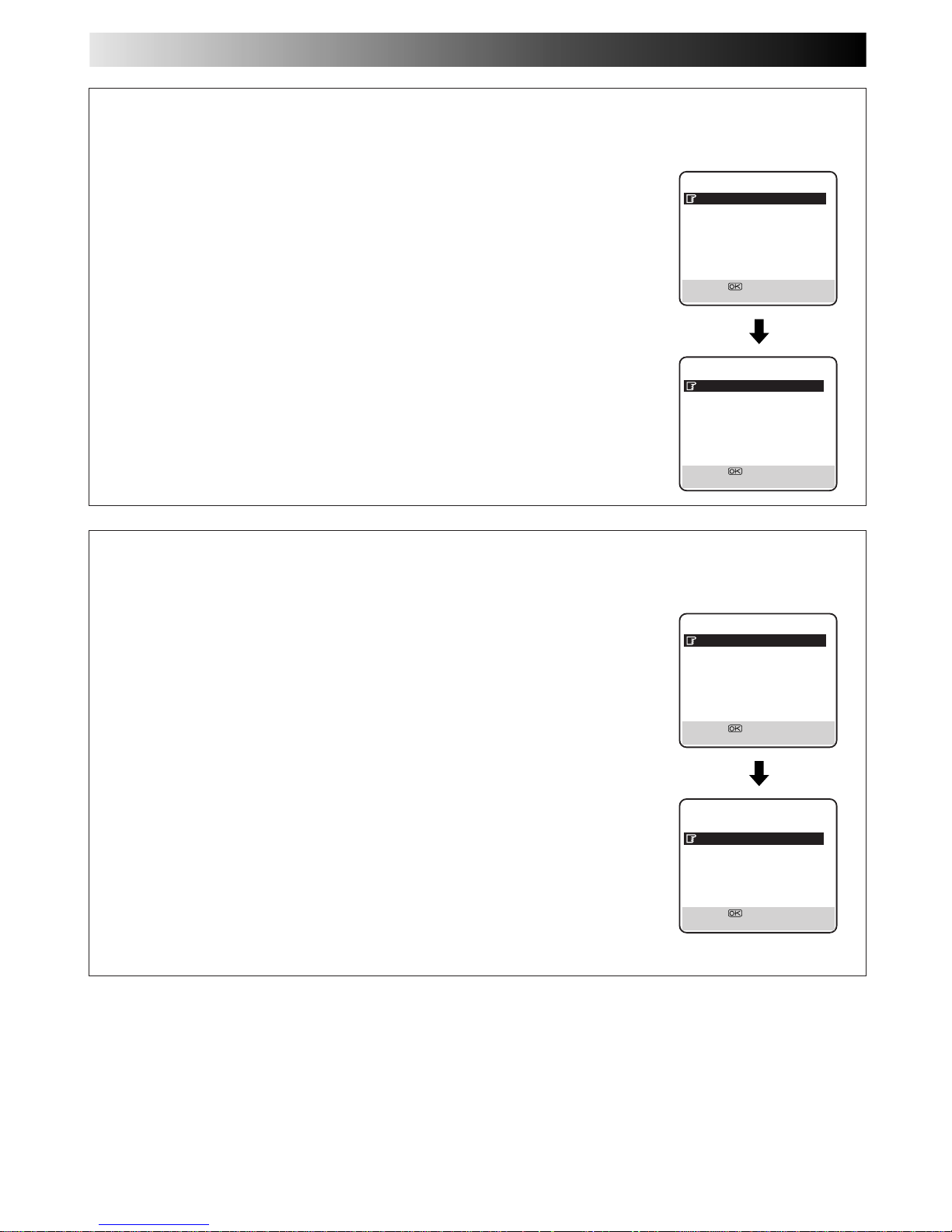
AV2 SELECT Setting
Set "AV2 SELECT" to the appropriate mode depending on the type of unit connected to the rear panel AV2 IN/DECODER
connector of this recorder.
1 Press MENU to access the Main Menu screen.
2 Press %fi to move the highlight bar (pointer) to "MODE SET", then press OK or
#
.
3 Press %fi to move the highlight bar (pointer) to "AV2 SELECT".
4 Press OK or
#
to select "AV2", "DECODER" or "SAT".
a–AV2 : To use this recorder as the recording deck with the player connected to the
AV2 IN/DECODER connector, or to use the satellite tuner connected to the
AV2 IN/DECODER connector.
b–DECODER : To use a decoder connected to the AV2 IN/DECODER connector.
If "AV1 SELECT" is set to "S-VIDEO" and "AV2 SELECT" is changed to
"DECODER", "AV1 SELECT" will be changed to "VIDEO" automatically.
c–SAT : To view a satellite programme with the TV set while the recorder is in
Timer mode, in Stop mode, recording or turned off. (Z pg. 53)
5 Press MENU to return to normal screen.
● If you have a satellite tuner or a decoder connected to the AV2 IN/DECODER connector, be
sure to set "AV2 SELECT" back to appropriate mode after editing.
● If you're not connecting a decoder to the AV2 IN/DECODER connector, leave "AV2 SELECT"
set to "AV2".
● The default setting is "AV2"; if the recorder's memory backup has expired due to a power cut
or because the AC was removed from the recorder, "AV2" will be automatically selected when
the power is restored to the recorder. If you are using a satellite tuner or a decoder, be sure to
set "AV2 SELECT" back to appropriate mode.
● If the AV1 OUT switch on the rear panel is set to Y/C, it is impossible to set "AV2 SELECT"
to "DECODER".
EDITING (cont.)
PREVIOUS PAGE
AV1 SELECT VIDEO
AV2 SELECT AV2
DV SOUND SOUND1
AUDIO REC NICAM
[5∞] =
[MENU] : EXIT
MODE SET
DSPC ON
O. S. D. ON
DIRECT RECORD ON
AUTO SP=LP TIMER OFF
DIGITAL 3R ON
POWER SAVE OFF
S-VHS AUTO
NEXT PAGE
[5∞] =
[MENU] : EXIT
AV1 SELECT Setting
Set "AV1 SELECT" to the appropriate mode depending on the type of unit connected to the rear panel AV1 IN/OUT connector of
this recorder.
1 Press MENU to access the Main Menu screen.
2 Press %fi to move the highlight bar (pointer) to "MODE SET", then press OK or
#
.
3 Press %fi to move the highlight bar (pointer) to "AV1 SELECT".
4 Press OK or
#
to select "VIDEO" or "S-VIDEO".
a–VIDEO : If a connected device's output is compatible only with regular video signals,
set "AV1 SELECT" to "VIDEO".
b–S-VIDEO : If a connected device's output is compatible with Y/C signals, set "AV1
SELECT" to "S-VIDEO". This setting will let you take advantage of higherquality S-VHS pictures.
5 Press MENU to return to normal screen.
● If "AV2 SELECT" is set to "DECODER", it is impossible to set "AV1 SELECT" to "S-VIDEO".
PREVIOUS PAGE
AV1 SELECT VIDEO
AV2 SELECT AV2
DV SOUND SOUND1
AUDIO REC NICAM
[5∞] =
[MENU] : EXIT
Page 14
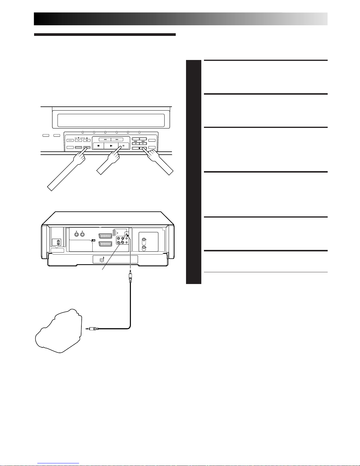
EN 51
The Synchro Editing function synchronizes the start of the
playback and recording operations when starting an edit
operation using a camcorder with LANC connector and your
video recorder.
Synchro Editing
(S-VHS/VHS Mode
Only)
MAKE CONNECTIONS
1
Connect your recorder to camcorder (Z pg. 46), and
connect your recorder's SYNCHRO EDIT connector to
the camcorder's LANC connector.
SET RECORDING MODE
2
Set the appropriate recording mode (S-VHS or VHS)
(Z pg. 23).
SET RECORDER'S INPUT
MODE
3
Set the appropriate input mode, depending on the
connectors being used in step 1.
LOCATE START POINT
4
Start playback of the tape in the camcorder, and pause
playback when you find the point where you want to
start editing. Press and hold PAUSE and press RECORD
on your recorder so that the recorder enters the RecordPause Mode.
START SYNCHRO EDITING
5
Press SYNCHRO EDIT.
PAUSE SYNCHRO EDITING
6
Press SYNCHRO EDIT again.
● Repeat steps 4 – 6 as necessary.
NOTES:
●
The Synchro Editing function is impossible with the connection using DV connector.
●
The Synchro Editing function may not work with the initial
part of a camcorder tape.
●
The Synchro Editing function cannot be used when using the
JLIP function. (Pressing SYNCHRO EDIT cancels the JLIP
function.)
●
The Synchro Editing function may not work properly with
some type of camcorder.
LANC Cable
(not provided)
Camcorder
Recorder
SYNCHRO EDIT
connector
Player
To LANC connector
PAUSE
RECORD
SYNCHRO EDIT
Page 15

52 EN
INFORMATION ON J TERMINAL
J Terminal (JLIP (Joint Level
Interface Protocol) Connector)
The J Terminal is used for service purposes.
Page 16
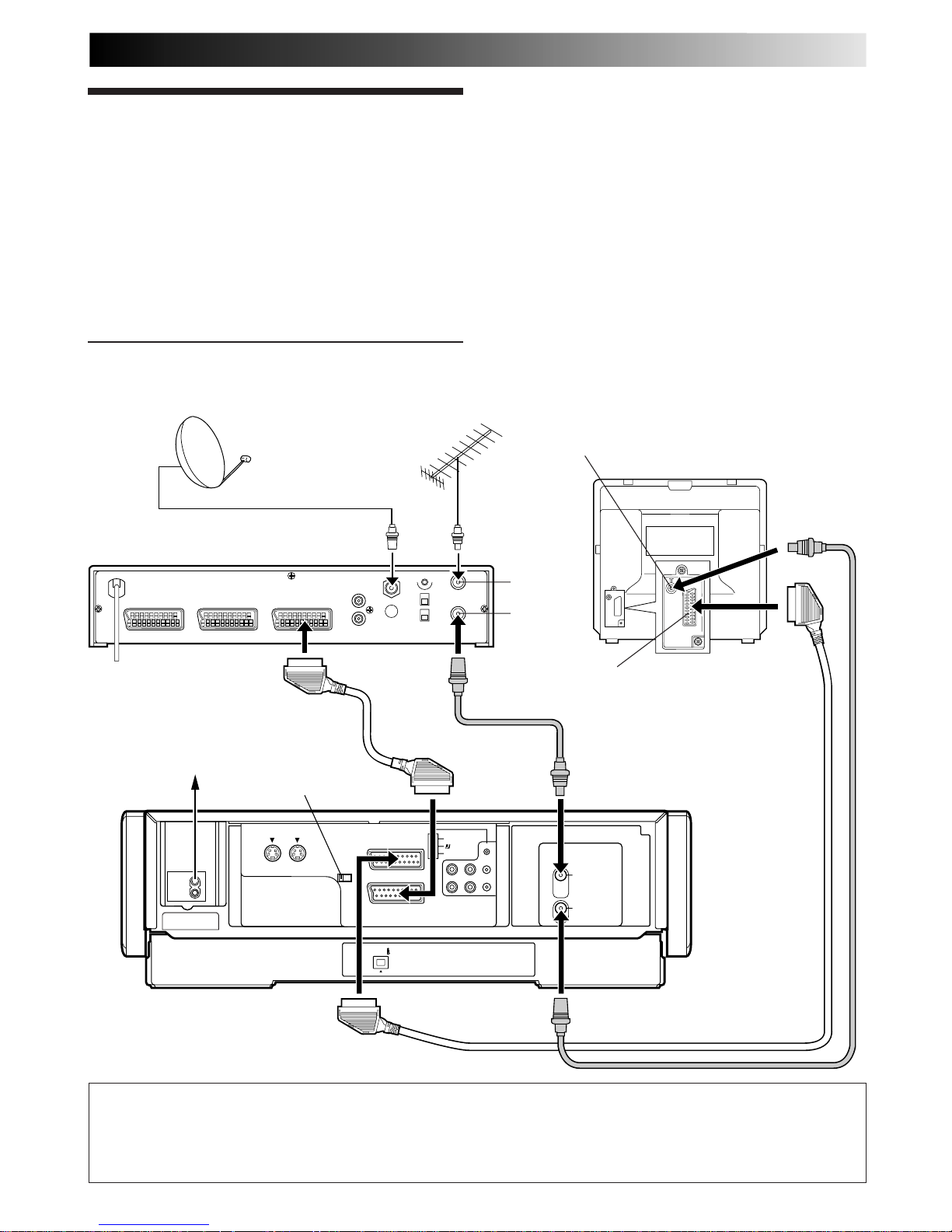
EN 53
SYSTEM CONNECTIONS
AV1 IN/OUT
(L-1)
AV2 IN/DECODER
(L-2)
DV IN
AV1 OUT
COMP. Y/C
S IN
(S-1)
S OUT
R.PAUSE
ANT. IN
ANT. OUT
R
L
AUDIO
OUT IN
(S-1)
SYNCHRO EDIT
JLIP
DECODER VCR TV
Connection To
A Satellite
Tuner
Simple Connections
This is an example of simple connection if your TV has
only one 21-pin SCART connector. . .
Connect the satellite tuner to the video recorder's AV2 IN/
DECODER connector, then connect the recorder's AV1 IN/OUT
connector to the TV's 21-pin SCART connector.
Mains outlet
TV Aerial
cable
Aerial connector
Satellite Tuner Unit
Satellite Cable
Outdoor Unit
Aerial
Back of TV
21-pin AV input
connector (SCART)
RF OUT
ANT. IN
Back of Recorder
IMPORTANT
When you set "AV2 SELECT" to "SAT" (Z pg. 50), it is possible to view a satellite broadcast with the TV set to its AV mode even
if the recorder is in Timer mode, in Stop mode, recording or turned off. When the recorder is in Stop mode or recording, press
VCR/TV on the remote control to turn off the VCR indicator on the display panel.
●
In this case, be sure to set the AV1 OUT switch on the rear panel to COMP.
AV1 OUT switch
NOTES:
●
Set "AV2 SELECT" to "AV2" or "SAT". (Z pg. 50)
●
You can use Automatic Satellite Program Recording function
(Z pg. 37) with this connection.
●
To record a programme via the satellite tuner, select L-2 mode
by pressing NUMBER keys and/or PROG. +/– so that "L-2"
appears on the display panel.
●
If both the satellite tuner and the TV have S-VIDEO connectors, you can enjoy high-quality S-VHS pictures. Connect
your recorder and the TV via S-VIDEO connection (Z pg. 7),
then connect the satellite tuner's S-VIDEO and AUDIO output
connectors to the recorder's S IN and AUDIO IN connectors
on the rear panel. Select S-1 mode by pressing NUMBER keys
and/or PROG.+/–, so that "S-1" appears on the display panel.
●
For details, refer to the instruction manual for the satellite
tuner.
Page 17
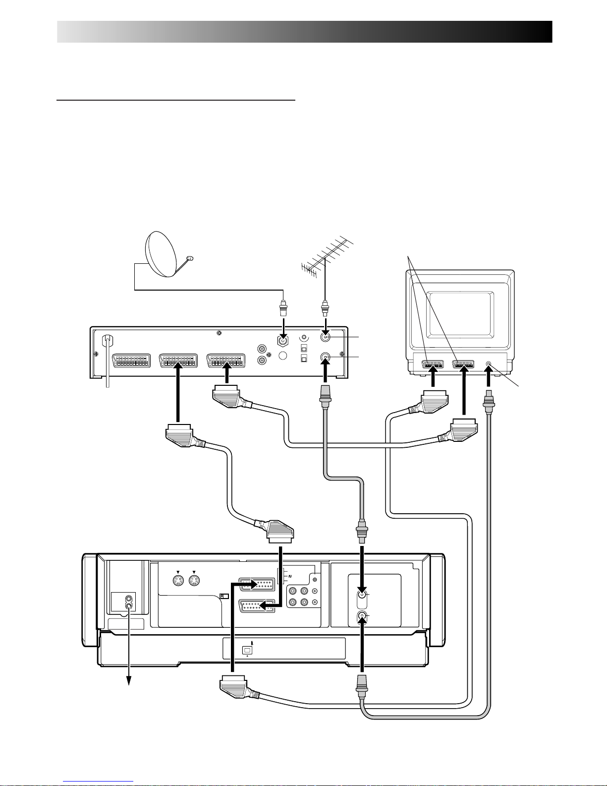
54 EN
AV1 IN/OUT
(L-1)
AV2 IN/DECODER
(L-2)
DV IN
AV1 OUT
COMP. Y/C
S IN
(S-1)
S OUT
R.PAUSE
ANT. IN
ANT. OUT
R
L
AUDIO
OUT IN
(S-1)
SYNCHRO EDIT
JLIP
DECODER VCR TV
EXT.2 EXT.1
Perfect Connections
This is an example of recommended connection if your
TV has more than two 21-pin SCART connectors. . .
Connect the satellite tuner's VCR connector to AV2 IN/DECODER
connector, and AV1 IN/OUT connector to TV's connector. Then
connect the satellite tuner and TV.
Mains outlet
TV Aerial
cable
Aerial
connector
Satellite Tuner Unit
Satellite Cable
Outdoor Unit
Aerial
Back of TV
21-pin AV input
connectors (SCART)
RF OUT
ANT. IN
Back of Recorder
NOTES:
●
Set "AV2 SELECT" to "AV2". (Z pg. 50)
●
You can use Automatic Satellite Program Recording function
(Z pg. 37) with this connection.
●
To record a programme via the satellite tuner, select L-2 mode
by pressing NUMBER keys and/or PROG. +/– so that "L-2"
appears on the display panel.
●
For details, refer to the instruction manual for the satellite
tuner and decoder.
SYSTEM CONNECTIONS (cont.)
Page 18
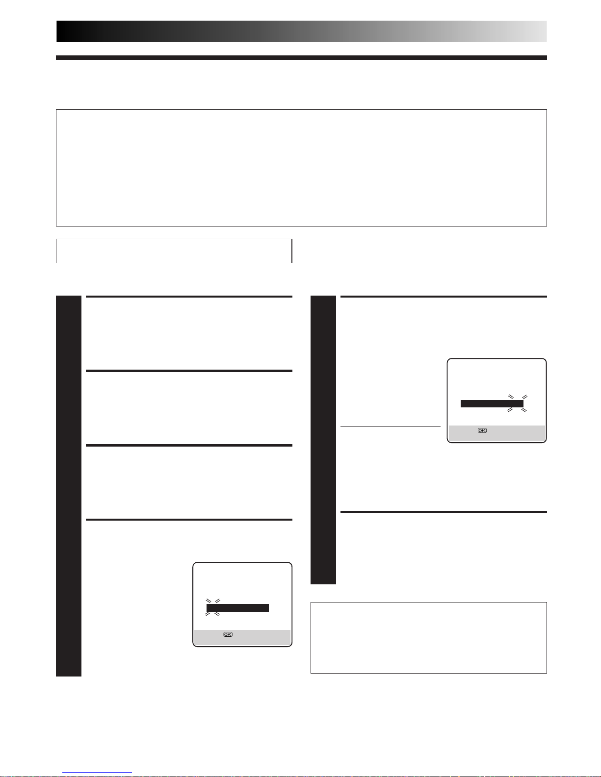
EN 55
VIDEO Plus+® Setup
IMPORTANT
Normally, Auto Set Up (Z pg. 8), Preset Download (Z pg. 10) or Auto Channel Set (Z pg. 56) sets the Guide Program Numbers
automatically. You need to set the Guide Program Numbers manually only in the following cases.
●
When timer-programming with the VIDEO Plus+ system, the channel position, where the station you wish to record is
received on your recorder, is not selected or when you add a channel after Auto Set Up or Auto Channel Set has taken place.
— Set the Guide Program Number for that station manually.
●
When you delete a channel or change channel positions manually after Auto Set Up or Auto Channel Set has taken place.
— Set the Guide Program Numbers for all the receivable stations manually.
●
When you wish to timer-record a satellite programme with the VIDEO Plus+ system.
— Set the Guide Program Numbers for all satellite broadcasts received on your satellite tuner.
Guide Program Number Set
ACCESS MAIN MENU
SCREEN
1
Press MENU.
ACCESS INITIAL SET
SCREEN
2
Press
%
fi
to move the highlight bar (pointer) to
"INITIAL SET", then press OK or #.
ACCESS GUIDE PROG SET
SCREEN
3
Press
%
fi
to move the highlight bar (pointer) to "GUIDE
PROG SET", then press OK or #.
ENTER GUIDE PROG
NUMBER
4
Press
%
fi
or NUMBER keys
to enter the Guide Program
number for the desired
station as shown in the TV
listings. Then press OK or #.
(Ex.) When inputting the
Guide Program
number 4 for CH4.
ENTER RECEIVING
CHANNEL POSITION
NUMBER
5
Press
%
fi
or NUMBER
keys to input the number
of the recorder's channel
position on which the
Guide Program number's
broadcast is received.
Then press OK or #.
● If the satellite broadcast
is received on your
recorder's auxiliary
channel "L-1" or "L-2",
select "L-1" or "L-2" for the channel position,
depending on the connection to the satellite tuner
(Z pg. 53, 54).
● Repeat steps 4 and 5 as necessary.
RETURN TO NORMAL
SCREEN
6
Press MENU.
(Ex.) If CH4 is received on
channel position 4.
Guide Program Number
"Guide Program (GUIDE PROG) number" refers to the
assigned TV station numbers, according to broadcast area,
for the VIDEO Plus+ timer recording. The Guide Program
numbers can be found in most TV listings.
GUIDE PROG SET
GUIDE PROG TV PROG
45
[
5
∞
] =
[MENU] : EXIT
GUIDE PROG SET
GUIDE PROG TV PROG
44
CH4
[
5
∞
] =
[MENU] : EXIT
Turn on the TV and select the AV mode.
SUBSIDIARY SETTINGS
Page 19
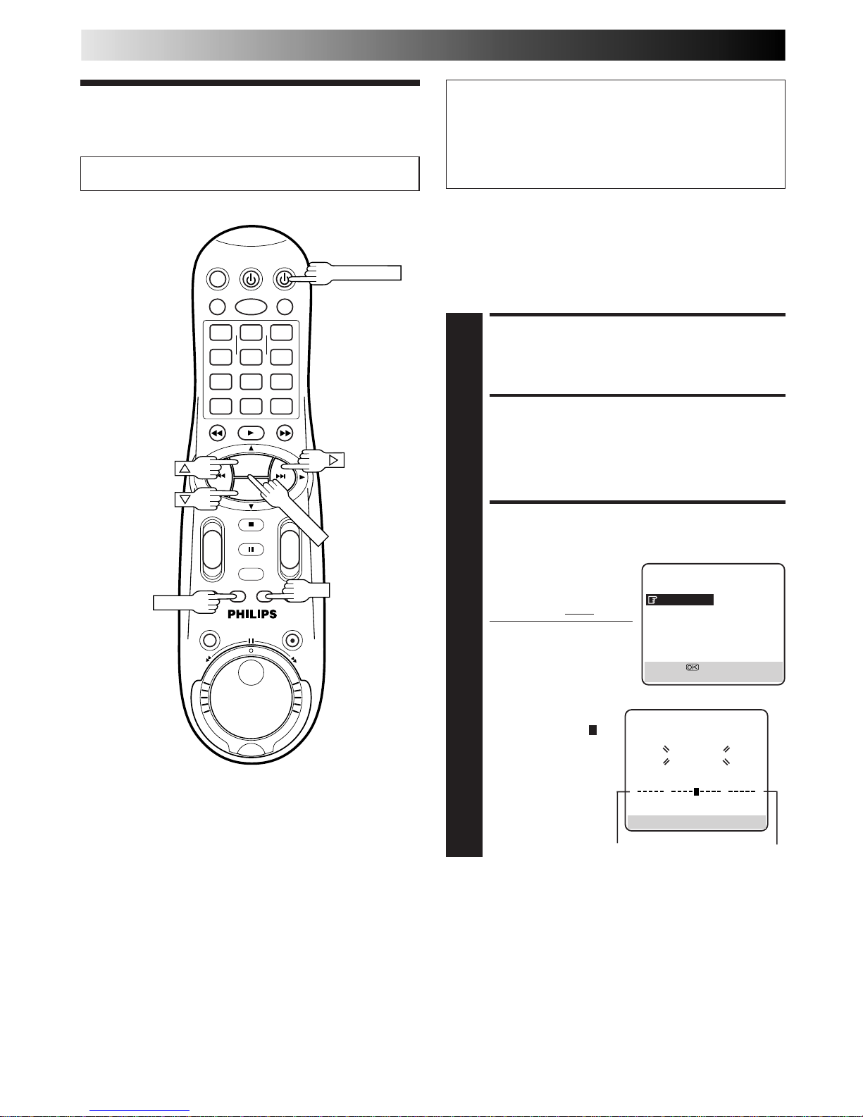
56 EN
SUBSIDIARY SETTINGS (cont.)
Tuner Set
IMPORTANT
Perform the following steps only if —
— Auto Channel Set has not been set correctly by Auto Set
Up function or by Preset Download (Z pg. 8, 10).
— you have moved to a different area or if a new station
starts broadcasting in your area.
Your recorder needs to memorize all necessary stations in
channel positions in order to record TV programmes. Auto
Channel Set automatically assigns all receivable stations in your
area to call them up by using the PROG. +/– buttons without
going through any vacant channel.
TURN ON THE RECORDER
1
Press VCR POWER.
ACCESS MAIN MENU
SCREEN
2
Press MENU.
ACCESS AUTO CH SET
SCREEN
3
Press
%
fi
to move the
highlight bar (pointer) to
"AUTO CH SET", then
press OK or # twice.
● The Auto Set screen
appears, and remains on
screen while the
recorder searches
for receivable
stations.
As Auto Channel Set
progresses, the " "
mark on the
screen moves from
left to right.
Wait until the
screen as shown in
step 4 appears.
Auto Channel Set
MAIN MENU
MODE SET
AUTO CH SET
MANUAL CH SET
INITIAL SET
TAPE MANAGER
[
5
∞
] =
[MENU] : EXIT
1
4
2 3
5
8
0
9
6
7
-+-
+
+
+
-
-
PROG. +
PROG. –
OK
PROG.+/–
MENU
VCR POWER
Turn on the TV and select the AV mode.
0
+++
End
Beginning
AUTO SET
PLEASE WAIT
[MENU] : EXIT
Page 20
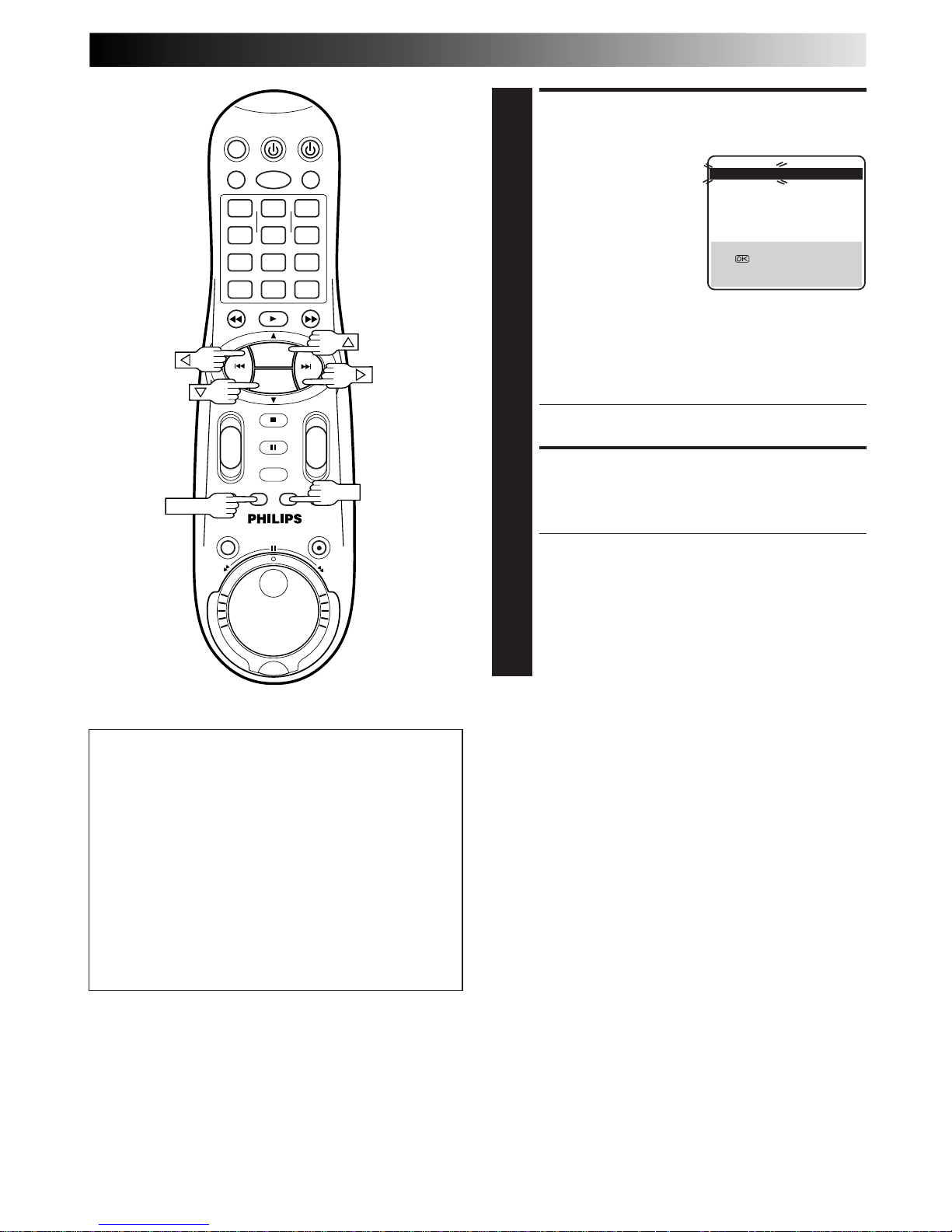
EN 57
VIEW CONFIRMATION
SCREEN
4
After "SCAN COMPLETED"
is displayed on the screen
for about 5 seconds, the
Confirmation screen
looking like the one to the
right appears. The stations
your recorder located
appear on a Confirmation
screen — channel
positions (PR), channels
(CH) and station names
(ID – Z pg. 62). The blueback screen and the
programme currently being broadcast by the blinking
station appear alternately for 8 seconds each.
To view the next page, use the %fi
@ #
button on the
remote control.
● The Guide Program numbers will also be set
automatically during Auto Channel Set.
RETURN TO NORMAL
SCREEN
5
Press MENU.
● Using the Confirmation screen, you can skip or add
channel positions, enter station names and perform
other operations. Refer to pages 58 – 61 for the
procedures.
● Depending on reception conditions, the stations may
not be stored in order, and the station names may not
be stored correctly.
● For information on scrambled broadcasts, refer to
page 59.
IMPORTANT
● In certain reception conditions, station names may not be
stored correctly, and auto Guide Program Number Set may
not work properly. If the Guide Program numbers are not set
properly, when you timer-record a TV programme using the
VIDEO Plus+ system, the recorder will record a TV
programme of a different station. When programming the
timer using the VIDEO Plus+ system, be sure to check
whether the channel position on which your recorder
receives the broadcasting station you wish to record is
selected (Z pg. 30, "VIDEO Plus+® Timer Programming").
● Your video recorder memorizes all detected stations even if
reception of some of them is poor. In these cases picture
quality may be poor. To delete those stations with an
unacceptable picture Z "Delete A Channel" on page 59.
NOTES:
●
Fine tuning is performed automatically during Auto Channel
Set. If you want to perform it manually, refer to page 60.
●
If you perform Auto Channel Set when the aerial cable is not
connected properly, "SCAN COMPLETED -NO SIGNAL-"
appears on the screen in step 7. When this happens, make
sure of the aerial connection and press OK; Auto Channel Set
will take place again.
1
4
2 3
5
8
0
9
6
7
-+-
+
+
+
-
-
PROG. +
PROG. –
OK
MENU
PR CH ID PR CH ID
01 26 BBC1 08 ––––
02 33 BBC2 09 ––––
03 23 ITV 10 ––––
04 30 CH4 11 ––––
05 37 CH5 12 ––––
06 –––– 13 ––––
07 –––– 14 ––––
[
5
∞
]
=
: EDIT
= [X] : DELETE
[MENU] : EXIT
5
5
5
Page 21
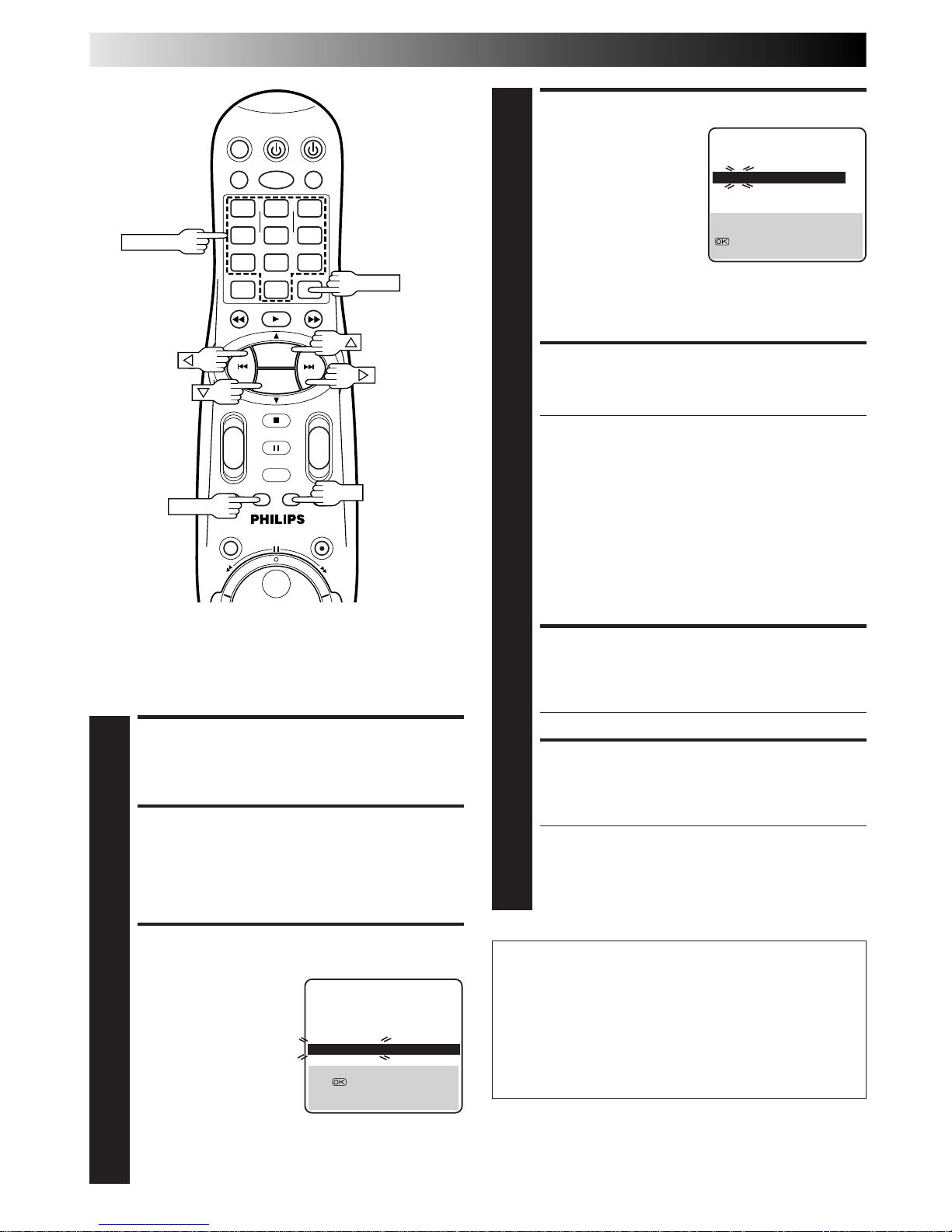
58 EN
SUBSIDIARY SETTINGS (cont.)
ATTENTION
Guide Program numbers are not set when channels are
stored manually. If an attempt is made at timer programming with the VIDEO Plus+ system in this state, the
"GUIDE PROG SET" screen appears; set the Guide Program
numbers on this screen. Z "ATTENTION – Regarding
Guide Program Number Set" on pg. 31.
Or perform "Guide Program Number Set" (Z pg. 55).
Storing Channels Manually
Store channels that were not stored during Auto Set Up (Z pg.
8), Preset Download (Z pg. 10) or Auto Channel Set (Z pg. 56).
SELECT BAND
4
Press
%
fi
to change the
band between CH (regular)
and CC (cable), then
press #.
INPUT CHANNEL
5
Press the NUMBER keys to input the channel number you
want to store.
● Input "0" before any single number entries.
● To input the registered station name (ID – Z pg. 62),
press # until "----" (ID setting) begins blinking, then
press
%
fi
.
● For fine tuning adjustment, press # until "+/–" begins
blinking, then press
%
fi
. While tuning, "+" or "–"
appears.
● When storing a channel that sends scrambled
broadcasts, press # until "OFF" (Decoder setting)
blinks, then press %fi to set "DECODER" to "ON"
("OFF" is the default setting).
● When "AV2 SELECT" is set to "AV2" or "SAT", the
"DECODER" setting cannot be changed (Z pg. 50).
ENTER NEW CHANNEL
INFORMATION
6
Press OK and the Confirmation screen appears.
● Repeat steps 3 through 6 as necessary.
CLOSE CONFIRMATION
SCREEN
7
Press MENU.
● To change positions, see "Change Station Channel
Position" (Z pg. 59).
● If you wish to set station names other than the ones
registered in your recorder, Z "Set Stations (B)" on
page 61.
The blueback screen and the
programme currently being
broadcast by the selected channel
appear alternately for 8 seconds
each.
The blueback screen and the
programme currently being
broadcast by the selected channel
appear alternately for 8 seconds
each.
ACCESS MAIN MENU
1
Press MENU.
ACCESS CONFIRMATION
SCREEN
2
Press %fi to move the highlight bar (pointer) to
"MANUAL CH SET", then press OK or #. The Confirmation screen appears.
SELECT POSITION
3
Press
%
fi
@ #
until an
open position in which
you want to store a
channel begins blinking,
then press OK. The
Manual Channel Set
screen appears.
(Ex.) To store in position 6.
PR CH ID FINE DECODER
06 CH01
– –␣ – –
+/– OFF
[
5
∞
] : SELECT
[
] : CURSOR +=
: OK
[MENU] : EXIT
∞
∞
1
4
2 3
5
8
0
9
6
7
-+-
+
+
+
-
-
PROG. +
PROG. –
OK
MENU
NUMBER
CLEAR
5
5
PR CH ID PR CH ID
01 26 BBC1 08 ––––
02 33 BBC2 09 ––––
03 23 ITV 10 ––––
04 30 CH4 11 ––––
05 37 CH5 12 ––––
06 –––– 13 ––––
07 –––– 14 ––––
[
5
∞
]
=
: EDIT
= [X] : DELETE
[MENU] : EXIT
Page 22
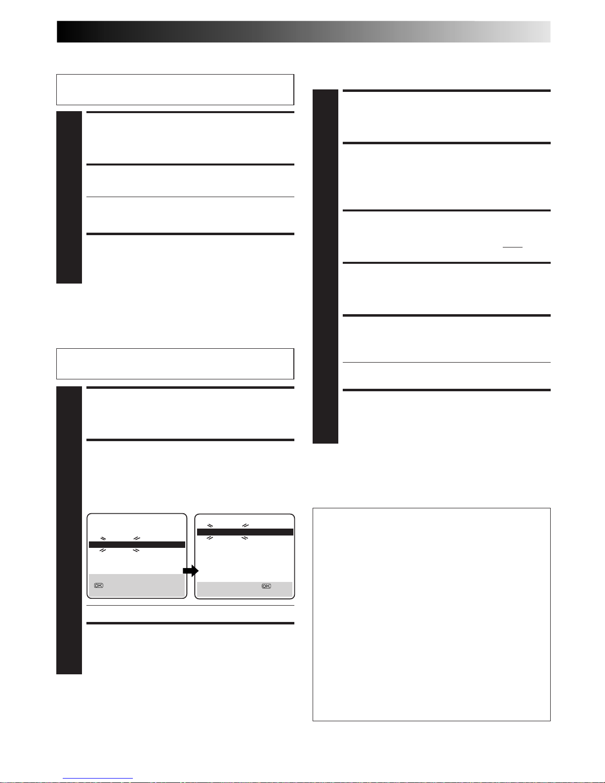
EN 59
Perform steps 1 and 2 of "Storing Channels Manually" on
page 58 to access the Confirmation screen before continuing.
Change Station Channel
Position
SELECT ITEM
1
Press
%
fi
@ #
until the item you want to move begins
blinking. Then press OK and the station name (ID) and
its channel (CH) number begin blinking.
SELECT NEW POSITION
2
Press
%
fi
@ #
to move the station to the new channel
position, then press OK.
Example: If you moved the station in position 4 to
position 2, the stations originally in positions
2 and 3 each move down one space.
● Repeat steps 1 and 2 as necessary.
CLOSE CONFIRMATION SCREEN
3
Press MENU.
SELECT ITEM
1
Press
%
fi
@ #
until the item you want to delete begins
blinking.
DELETE CHANNEL
2
Press CLEAR.
● The item directly beneath the cancelled one moves
up one line.
● Repeat steps 1 and 2 as necessary.
CLOSE CONFIRMATION SCREEN
3
Press MENU.
Delete A Channel
Perform steps 1 and 2 of "Storing Channels Manually" on
page 58 to access the Confirmation screen before continuing.
SELECT DECODER MODE
1
Set "AV2 SELECT" to "DECODER" (Z pg. 50).
ACCESS CONFIRMATION
SCREEN
2
Perform steps 1 and 2 of "Storing Channels Manually"
on page 58.
SELECT POSITION
3
Press
%
fi
@ #
to select the channel position broadcast-
ing scrambled programmes, then press OK twice.
CHANGE DECODER SETTING
4
Press # until "OFF" (decoder setting) begins blinking,
and set it to "ON" by pressing
%
fi
.
RETURN TO CONFIRMATION
SCREEN
5
Press OK.
● Repeat steps 3 through 5 as necessary.
CLOSE CONFIRMATION SCREEN
6
Press MENU.
NOTE:
Scrambled programmes are not currently broadcasted in the U.K.
When Receiving A
Scrambled Broadcast
ATTENTION
If channel positions are changed or deleted, the Guide
Program numbers that have been set are reset.
● Example 1:If a channel is deleted, all the Guide Program
numbers are reset.
● Example 2:If a channel is changed from position 4 to
position 2, the Guide Program numbers
above position 4 are reset.
● Example 3:If a channel is changed from position 4 to
position 6, the Guide Program numbers
above position 6 are reset.
* In Examples 2 and 3, if the channel is moved to position
10 before OK is pressed, the Guide Program numbers
above position 10 are reset.
If an attempt is made at timer programming with the
VIDEO Plus+ system in this state, the "GUIDE PROG
SET" screen appears; set the Guide Program numbers on
this screen. Z "ATTENTION – Regarding Guide Program
Number Set" on pg. 31.
Or perform "Guide Program Number Set" (Z pg. 55).
PR CH ID PR CH ID
01 26 BBC1 08 ––––
02 23 ITV 09 ––––
03 30 CH4 10 ––––
04 33 BBC2 11 ––––
05 37 CH5 12 ––––
06 –––– 13 ––––
07 –––– 14 ––––
[
5
∞
] : MOVE
: MANUAL CH SET
[MENU] : EXIT
PR CH ID PR CH ID
01 26 BBC1 08 ––––
02 33 BBC2 09 ––––
03 23 ITV 10 ––––
04 30 CH4 11 ––––
05 37 CH5 12 ––––
06 –––– 13 ––––
07 –––– 14 ––––
[
5
∞
] : MOVE =
[MENU] : EXIT
5
5
5
5
Page 23
60 EN
SUBSIDIARY SETTINGS (cont.)
Perform steps 1 and 2 of "Storing Channels Manually" on
page 58 to access the Confirmation screen before continuing.
SELECT CHANNEL TO
FINE-TUNE
1
Press
%
fi
@ #
until the channel you want to tune begins
blinking.
ACCESS MANUAL
CHANNEL SET SCREEN
2
Press OK twice. The Manual Channel Set screen
appears.
PERFORM TUNING
3
Press # until "+/–" begins blinking, then press
%
fi
until
the picture is its clearest. Then press OK.
● The Confirmation screen appears.
● Repeat steps 1 through 3 as necessary.
CLOSE CONFIRMATION
SCREEN
4
Press MENU.
Fine-Tuning Channels
Already Stored
1
4
2 3
5
8
0
9
6
7
-+-
+
+
+
-
-
PROG. +
PROG. –
OK
MENU
Page 24
EN 61
SELECT STATION NAME
CHARACTER
1
Press # until the first letter
of the station name begins
blinking.
ENTER NEW CHARACTER
2
Press %fi to cycle through the characters (A–Z, 0–9, –,
*
, +, (space) ) and stop when the desired character
is indicated, then press
#
to enter. Enter the remaining
characters the same way (maximum of 4).
After entering all characters, press OK.
● The Confirmation screen appears.
● If you make a mistake, press @ until the incorrect
character begins blinking. Then enter the correct
character by pressing %fi.
CLOSE CONFIRMATION
SCREEN
3
Press MENU.
Set Stations (B)
Perform steps 1 and 2 of "Storing Channels Manually" on
page 58 to access the Confirmation screen before continuing.
SELECT ITEM
1
Press %fi
@ #
until the item you want begins blinking.
ACCESS MANUAL
CHANNEL SET SCREEN
2
Press OK twice.
SELECT NEW STATION
3
Press # until the station
name (ID) begins blinking,
then press %fi until the
new station’s name (ID)
you want to store begins
blinking.
Registered station names
(Z pg. 62) appear as you
press %fi.
SWITCH STATIONS
4
Press OK.
● The Confirmation screen appears.
● Repeat steps 1 through 4 as necessary.
CLOSE CONFIRMATION
SCREEN
5
Press MENU.
Set Stations (A)
Set station names that are registered in your recorder.
Perform steps 1 and 2 of "Storing Channels Manually" on
page 58 to access the Confirmation screen and then perform
step 1 and 2 of "Set Stations (A)" on the left before continuing.
Set station names other than the ones registered in your recorder.
PR CH ID FINE DECODER
06 CH45
– –␣ – –
+/– OFF
[
5
∞
] : CHANGE ID
[
] : CURSOR +=
: OK
[MENU] : EXIT
∞
∞
PR CH ID FINE DECODER
06 CH45 BBC1 +/– OFF
[
5
∞
] : A-Z, 0-9
[
] : CURSOR +=
: OK
[MENU] : EXIT
∞
∞
NOTE:
The characters available for the station name (ID) are A–Z, 0–9,
–, *, +, (space) (maximum of 4).
Page 25

62 EN
SUBSIDIARY SETTINGS (cont.)
TV Station And ID List
STATION NAME ID*
Anglia TV ANGL
ARD ARD
ARTE ARTE
BBC Group BBC
BBC1 BBC1
BBC2 BBC2
Berlin 1 BLN1
Berlin 2 BLN2
Border TV BORD
Bayern1 BR1
Bayern3 BR3
BRT1 BRT1
BRT2 BRT2
Children Ch CHLD
Canal + CH+
CNN CNN
Channel TV CHNL
Central TV CNTR
Channel 4 CH 4
Channel 5 CH 5
DRS DRS
DR TV DRTV
DSF DSF
Euronews EURN
Euronews EURO
Eurosports EURS
France1 FR1
France2 FR2
France3 FR3
Granada TV GRNA
Grampian TV GRMP
Hessen1 HR1
Hessen3 HR3
HRT HRT
HTV HTV
ITV Network ITV
Kabelkanal KABL
London LNDN
MDR MDR
MTV MTV
Nord3 N3
NDR1 NDR1
NDR3 NDR3
NED1 NED1
NED2 NED2
NED3 NED3
Network 2 NET2
NRK NRK
N-TV N-TV
Offener Kanal OKAN
ORF1 ORF1
ORF2 ORF2
ORF3 ORF3
OWL 3 OWL3
Premiere PRMI
PR07 PR07
RAI1 RAI1
RAI2 RAI2
RAI3 RAI3
RB1 RB1
RB3 RB3
Rikisutvarpid-S RKPS
RTBF 1 RTB1
RTBF 2 RTB2
RTE 1 RTE1
RTL RTL
RTL 2 RTL2
RTP RTP
STATION NAME ID*
SAT SAT
SAT 1 SAT1
Scottish TV SCOT
SC4 SC4
SDR SDR
SDR1 SDR1
SFB1 SFB1
SFB3 SFB3
SKY SKY
Sky One SKY1
Sky Net SKYN
Sport SPRT
SR 1 SR1
Super RTL SRTL
STV Test STVT
STV 1 STV1
STV 2 STV2
Suedwest3 SWR
SWF 1 SWF1
Schweiz4 SWZ4
TYNE TEES TEES
Text TEXT
TF1 TF1
TNT int TNT
TRT int TRT
TSI TSI
TSR TSR
TSW TSW
TVE TVE
TV Polonia TVPA
TVP 1 TVP1
TVP 2 TVP2
TVS TVS
TV2 TV2
TV5 TV5
Tele Zurich TZUR
Ulster TV ULST
Veronica VERN
VIVA VIVA
VIVA2 VIV2
VOX VOX
VTM VTM
VT4 VT4
West1 WDR1
West3 WDR3
YLE 1 YLE1
YLE 2 YLE2
Yorkshire TV YORK
ZDF ZDF
Zurich 1 ZUR1
3SAT 3SAT
* The "ID" abbreviation is what is shown on-screen in lieu of the
station name. The "ID" abbreviation is listed in the Confirmation screen and is displayed on the TV screen each time the
recorder is tuned to a different station.
Page 26

EN 63
TV Station Channel Number Guide
Only the main stations are listed. There are in addition many relay stations, and full lists are available from the BBC
and ITV.
BBC1 BBC2 ITV CH4 CH5
London & South-East
Bluebell Hill ........................... 40 46 43 65 —
Crystal Palace ........................ 26 33 23 30 37
Dover ..................................... 50 56 66 53 —
Heathfield .............................. 49 52 64 67 —
Oxford ................................... 57 63 60 53 49
South-West
Beacon Hill ............................ 57 63 60 53 —
Caradon Hill .......................... 22 28 25 32 —
Huntshaw Cross ..................... 55 62 59 65 67
Redruth .................................. 51 44 41 47 37
Stockland Hill ........................ 33 26 23 29 —
Channel Islands
Fremont Point ........................ 51 44 41 47 —
South
Hannington ............................ 39 45 42 66 35
Midhurst ................................ 61 55 58 68 —
Rowridge ............................... 31 24 27 21 —
West
Mendip .................................. 58 64 61 54 37
East
Sandy Heath .......................... 31 27 24 21 39
Sudbury ................................. 51 44 41 47 35
Tacolneston ............................ 62 55 59 65 52
Midlands
Ridge Hill ............................... 22 28 25 32 35
Sutton Coldfield ..................... 46 40 43 50 37
The Wrekin ............................ 26 33 23 29 35
Waltham ................................ 58 64 61 54 35
North
Belmont ................................. 22 28 25 32 56
Emley Moor ........................... 44 51 47 41 37
BBC1 BBC2 ITV CH4 CH5
North-West
Caldbeck ................................ 30 34 28 32 56
Winter Hill ............................. 55 62 59 65 48
North-East
Bilsdale West Moor ................ 33 26 29 23 35
Chatton .................................. 39 45 49 42 —
Pontop Pike ............................ 58 64 61 54 68
Scotland
Angus ..................................... 57 63 60 53 —
Black Hill ............................... 40 46 43 50 37
Sandale .................................. 22 — — — —
Caldbeck ................................ — 34 28 32 56
Creigkelly ............................... 31 27 24 21 48
Darvel .................................... 33 26 23 29 35
Durris ..................................... 22 28 25 32 67
Eitshal .................................... 33 26 23 29 —
Keelylang Hill ........................ 40 46 43 50 —
Knock More ........................... 33 26 23 29 —
Rosemarkie ............................ 39 45 49 42 67
Rumster Forest ....................... 31 27 24 21 —
Selkirk .................................... 55 62 59 65 52
Wales
Blaenplwyf ............................. 31 27 24 21 56
Carmel ................................... 57 63 60 53 —
Llanddona .............................. 57 63 60 53 —
Moel-y-Parc ........................... 52 45 49 42 —
Presely ................................... 46 40 43 50 37
Wenvoe ................................. 44 51 41 47 —
Northern Ireland
Brougher Mountain ................ 22 28 25 32 —
Divis ...................................... 31 27 24 21 37
Limavady ............................... 55 62 59 65 —
For customers in the U.K.
Page 27
64 EN
Just Clock
The Just Clock function provides accurate time keeping
through automatic adjustments at regular intervals, by
reading data from a PDC signal.
The Just Clock option can be set "ON" or "OFF" at the Clock
Set screen (the default setting is "ON"). Press OK until the
Just Clock setting begins blinking, then press %fi to change
the setting.
IMPORTANT: If you turn off Just Clock, the accuracy of your
recorder's built-in clock may be reduced, which could
adversely effect timer recording.
TURN THE RECORDER ON
1
Press VCR POWER.
ACCESS MAIN MENU
SCREEN
2
Press MENU.
ACCESS INITIAL SET
SCREEN
3
Move the highlight bar (pointer) to "INITIAL SET" by
pressing %fi, then press OK or #.
ACCESS CLOCK SET
SCREEN
4
Move the highlight bar (pointer) to "CLOCK SET" by
pressing %fi, then press OK or #. The Clock Set screen
appears.
SET DATE AND TIME
5
Press %fi to set the time, then press OK or #. The "date"
display begins blinking. Repeat the same procedure to
set the date and year.
● When you set the time, press and hold %fi to
change the time by 30 minutes.
● When you set the date, press and hold %fi to
change the date by 15 days.
Clock Set
IMPORTANT
If you performed Auto Set Up (Z pg. 8), Preset Download
(Z pg. 10) or Auto Channel Set (Z pg. 56), without ever
having set the clock previously, the recorder's built-in
clock is also set automatically.
Perform the following steps only if —
— Auto Clock Set has not been performed correctly by
Auto Set Up, Preset Download or Auto Channel Set.
or
— the recorder's memory backup has expired.
or
— you want to change Just Clock setting (Z "Just Clock"
in the left column).
CLOCK SET
TIME DATE YEAR
0: 00 01 . 01 99
JUST CLOCK : ON
TV PR. : 1
[
5
∞
] =
[MENU] : EXIT
INTIAL SET
CLOCK SET
GUIDE PROG SET
JLIP ID NO. SET
[
5
∞
] =
[MENU] : EXIT
SUBSIDIARY SETTINGS (cont.)
1
4
2 3
5
8
0
9
6
7
-+-
+
+
+
-
-
PROG. +
PROG. –
OK
MENU
VCR POWER
Turn on the TV and select the AV mode.
Page 28
EN 65
NOTES:
●
Just Clock (when set to "ON") adjusts the recorder's built-in
clock every hour, except for 23:00, 0:00, 1:00 and 2:00.
●
Just Clock is not effective when . . .
– the recorder’s power is on.
– the recorder is in the Timer mode.
– a difference of more than 3 minutes exists between the
built-in clock’s time and the actual time.
– the recorder is in the Auto Satellite Prog Rec mode
(Z pg. 37).
– the recorder is in the Power Save mode (Z pg. 13).
●
If Just Clock is set to "ON", the recorder’s clock is automatically adjusted at the start/end of Summer Time.
●
Just Clock may not function properly depending on the
reception condition.
SET JUST CLOCK
6
The default setting is "ON". Set as desired by pressing
%fi, then press OK or #.
● For the Just clock function, Z "Just Clock" on page
64.
● If you set to "OFF", you can disregard the next step as
you won’t be able to receive regular clock adjustments.
SET CLOCK DATA SOURCE
CHANNEL POSITION
7
The recorder is preset to receive clock setting and
adjustment data from channel position 1. Press %fi to set
the channel position to the number representing the
station transmitting clock setting data, then press OK or #.
START CLOCK OPERATION
8
Press MENU.
1
4
2 3
5
8
0
9
6
7
-+-
+
+
+
-
-
PROG. +
PROG. –
OK
MENU
Page 29
66 EN
TROUBLESHOOTING
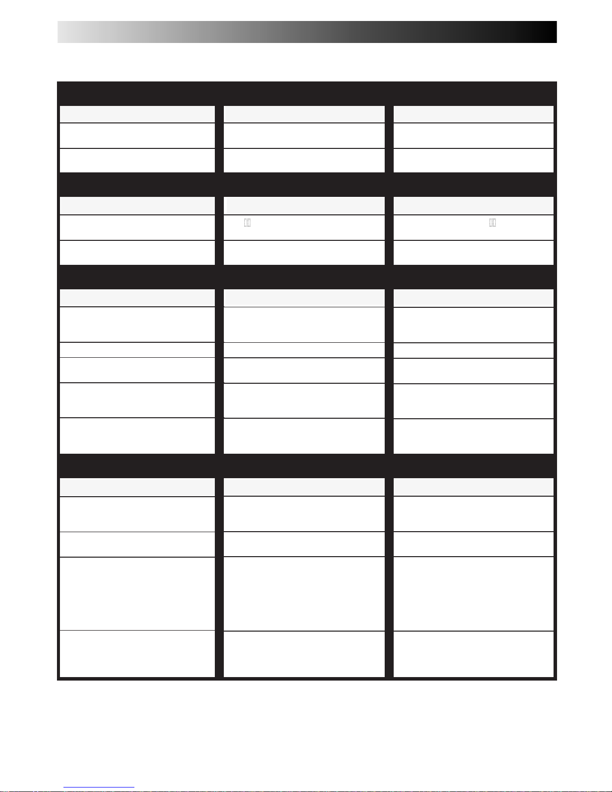
Before requesting service for a problem, use this chart and see if you can repair the trouble yourself. Small problems are often easily
corrected, and this can save you the trouble of sending your video recorder off for repair.
POSSIBLE CAUSE
● The mains power cord is disconnected.
● The batteries are discharged.
SYMPTOM
1. No power is applied to the
recorder.
2. The remote control won't function.
CORRECTIVE ACTION
Connect the mains power cord.
Replace the dead batteries with new
ones.
SYMPTOM
1. The tape does not run during
recording.
2. The tape will not rewind or fastforward.
CORRECTIVE ACTION
Press PLAY to turn the " " indicator
off.
Check the cassette.
SYMPTOM
1. The playback picture does not
appear while the tape is running.
2. Noise appears during visual search.
3. Noise appears during normal
playback.
4. The playback picture is blurred or
interrupted while TV broadcasts
are clear.
5. Breaks are noticeable in Hi-Fi
soundtrack.
POSSIBLE CAUSE
● If you’re using the AV or S-VIDEO
connection, the TV receiver is not
set to the AV mode.
● This is normal.
● The automatic tracking mode is
engaged.
● The video heads may be dirty.
● Automatic tracking is engaged.
CORRECTIVE ACTION
If you are using the AV or S-VIDEO
connection, set the TV to its AV mode.
Try manual tracking. (Z pg. 17)
Consult your PHILIPS dealer.
Engage and adjust tracking manually
(Z pg. 17), or set the soundtrack to
"NORM" (Z pg. 21).
POSSIBLE CAUSE
● " " is displayed on the display
panel.
● The tape is already fully rewound or
fast-forwarded.
CORRECTIVE ACTION
Insert a cassette, or using adhesive
tape, reseal the slot where the tab was
removed.
Set to the desired channel.
Confirm that the source is properly
connected.
Confirm that all units’ power switches
are turned on.
Set the input mode to "I-1", "L-1", "L-2",
"F-1", "S-1" or "S-2".
Confirm that the camcorder is
properly connected.
Set the input mode to "I-1", "L-1", "L-2",
"F-1", "S-1" or "S-2".
POSSIBLE CAUSE
● There is no cassette loaded, or the
cassette loaded has had its Record
Safety tab removed.
● "I-1", "L-1", "L-2", "F-1", "S-1" or "S-2"
has been selected as the input mode.
● The source (another video recorder,
camcorder) has not been properly
connected.
● All necessary power switches have
not been turned on.
● The input mode is not correct.
● The camcorder has not been
properly connected.
● The input mode is not correct.
SYMPTOM
1. Recording cannot be started.
2. TV broadcasts cannot be recorded.
3. Tape-to-tape editing is not possible.
4. Camcorder recording is not
possible.
POWER
PLAYBACK
RECORDING
TAPE TRANSPORT
Page 30
EN 67
CORRECTIVE ACTION
Re-perform the clock and/or timer
settings.
Press VCR POWER and confirm that
"‰" is displayed on the display panel.
Timer programming can’t be
performed while a timer recording is
in progress. Wait until it finishes.
Load a cassette with the Record
Safety tab intact, or cover the hole
using adhesive tape.
Remove the cassette and cover the
hole with adhesive tape, or insert a
cassette with the Record Safety tab
intact.
The programme may not have been
recorded in its entirety. Next time
make sure you have enough time on
the tape to record the entire
programme.
When the front panel is closed and
the cassette cannot be ejected fully,
push the cassette into the recorder,
then press EJECT to remove the
cassette.
Refer to "Guide Program Number Set"
and re-perform the procedure
(Z pg. 55).
SYMPTOM
1. Timer recording won’t work.
2. Timer programming is not possible.
3. "‰" and "]" on the display panel
won’t stop blinking.
4. The cassette is automatically
ejected, and "‰" and "]" on the
display panel won’t stop blinking.
5. The cassette is automatically
ejected, the power shuts off and
"‰" and "]" won’t stop blinking.
However, the cassette may not be
ejected when the front panel is
closed.
6. The VIDEO Plus+ system does not
timer-record properly.
POSSIBLE CAUSE
● The clock and/or the timer have
been set incorrectly.
● The timer is not engaged.
● Timer recording is in progress.
● The timer is engaged but there’s no
cassette loaded.
● The loaded cassette has had its
Record Safety tab removed.
● The end of the tape was reached
during timer recording.
● The recorder’s channel positions
have been set incorrectly.
CORRECTIVE ACTION
Position the camcorder so its
microphone is away from the TV.
Turn the TV’s volume down.
If you need the skipped channels,
restore them (Z pg. 58).
Press PAUSE to pause the recording,
change channels, then press PLAY to
resume recording.
Perform manual setting again.
Connect the TV aerial cable to the
recorder properly and turn off the
recorder power once, then turn the
recorder power back on again. The
recorder will try Auto Set Up again
(Z pg. 8).
Re-set the remote control to the
correct brand (Z pg. 75).
SYMPTOM
1. Whistling or howling is heard from
the TV during camcorder recording.
2. When scanning channels, some of
them are skipped over.
3. The channel cannot be changed.
4. Channel settings that were made
manually seem to have changed or
disappeared.
5. No channels are stored in the
recorder's memory.
6. The remote control won’t operate
the TV.
POSSIBLE CAUSE
● The camcorder’s microphone is too
close to the TV.
● The TV’s volume is too high.
● Those channels have been desig-
nated to be skipped.
● Recording is in progress.
● After the manual settings were
made, Auto Channel Set was
performed.
● The TV aerial cable was not
connected to the recorder when
Auto Set Up was performed.
● The remote control brand setting is
incorrect.
TIMER RECORDING
OTHER PROBLEMS
Page 31

68 EN
TROUBLESHOOTING (cont.)
Error Code
Some error codes may appear on the TV screen when operating the recorder. Refer to the chart below for the solution.
102
103
104
105
200
201
205
300
ERROR CODE SYMPTOM SOLUTION
● When a signal in which only the analog
information is copy protected has been input for
the dubbing in D-VHS mode.
● When a signal which is digitally copy protected
has been input for dubbing in D-VHS mode.
● When a signal which cannot be digitally converted
by the recorder has been recorded.
● When making an S-VHS/VHS recording of a signal
from DV IN connector (i.Link).
● When a signal which cannot be digitally converted
by the recorder has been input and played back.
● When normal playback is impossible such as with
a mosaic (block-shaped noise).
● When an attempt is made to play back a D-VHS
recorded tape that has been found to be invalid.
● When a signal which cannot be digitally converted
by the recorder has been input.
It is not possible to record a digitally copy protected
signal.
It is not possible to record a digitally copy protected
signal.
Sometimes a programme can be recorded but not
played back because the signal system is not
supported by the recorder. Switch to analog input
such as "L-1" to record.
The recorder’s DV IN connector (i.Link) is especially
for D-VHS recording. The digital signal is not
converted to analog and then recorded. Switch to
analog input such as "L-1" to record.
Playback is impossible because a signal system not
supported by the recorder has been input.
The recorder is making adjustments in order to
display normal picture. Please wait.
This tape cannot be played back by this recorder.
Nothing can be seen or heard because the signal
system is not supported by the recorder.
Page 32
EN 69
QUESTIONS AND ANSWERS
PLAYBACK
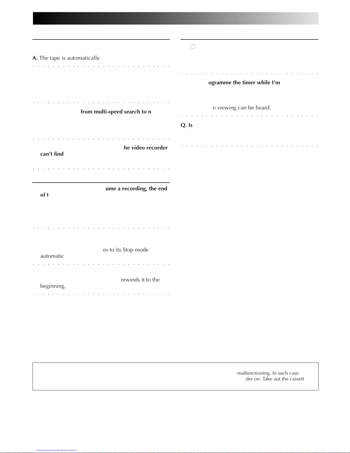
Q. What happens if the end of the tape is reached
during playback or search?
○○○○○○○○○○○○○○○○○○○○○○○○○○○○
A. The tape is automatically rewound to the beginning.
Q. Can the video recorder indefinitely remain in the
still mode?
A. No. It stops automatically after 5 minutes to protect
○○○○○○○○○○○○○○○○○○○○○○○○○○○○
the heads.
Q. When returning from multi-speed search to normal
playback, the picture is disturbed. Should I be
concerned about this?
○○○○○○○○○○○○○○○○○○○○○○○○○○○○
A. No, it is normal.
Q. Sometimes, during Index Search, the video recorder
can’t find the programme I want to see. Why not?
○○○○○○○○○○○○○○○○○○○○○○○○○○○○
A. There may be index codes too close together.
RECORDING
Q. When I pause and then resume a recording, the end
of the recording before the pause is overlapped by
the beginning of the continuation of recording. Why
does this happen?
A. This is normal. It reduces distortion at the pause and
○○○○○○○○○○○○○○○○○○○○○○○○○○○○
resume points.
Q. Can the video recorder indefinitely remain in the
Record-Pause mode?
A. No. The video recorder goes to its Stop mode
○○○○○○○○○○○○○○○○○○○○○○○○○○○○
automatically after 5 minutes to protect the heads.
Q. What happens if the tape runs out during recording?
A. The video recorder automatically rewinds it to the
○○○○○○○○○○○○○○○○○○○○○○○○○○○○
beginning.
TIMER RECORDING
Q. " " and "‰" remain lit on the display panel. Is there
a problem?
A. No. This is a normal condition for a timer recording in
○○○○○○○○○○○○○○○○○○○○○○○○○○○○
progress.
Q. Can I programme the timer while I’m watching a
tape or a TV broadcast?
A. You won’t see the picture as it is replaced by the on-
screen menu, but the audio from the programme or
○○○○○○○○○○○○○○○○○○○○○○○○○○○○
tape you’re viewing can be heard.
Q. Is it possible to timer-record a TV programme
broadcast in 2000?
○○○○○○○○○○○○○○○○○○○○○○○○○○○○
A. Yes, it is possible.
ATTENTION
This recorder contains microcomputers. External electronic noise or interference could cause malfunctioning. In such cases,
switch the recorder off and unplug the mains power cord. Then plug it in again and turn the recorder on. Take out the cassette.
After checking the cassette, operate the unit as usual.
Page 33
70 EN
INDEX
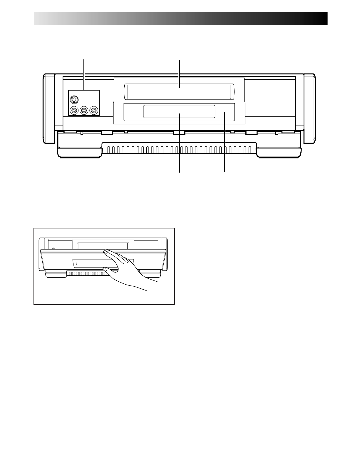
FRONT VIEW
VIDEO L RAUDIO
S-VIDEO
1
2
3
4
1 S-VIDEO/VIDEO/AUDIO Input Connectors
Z pg. 46
2 Cassette Loading Slot
OFF
B
A
REMOTE
VIDEO(MONO)L RAUDIO
Pull the front panel to access covered buttons/connectors.
3 Display Panel Z pg. 73
4 Infrared Beam Receiving Window
Page 34
EN 71
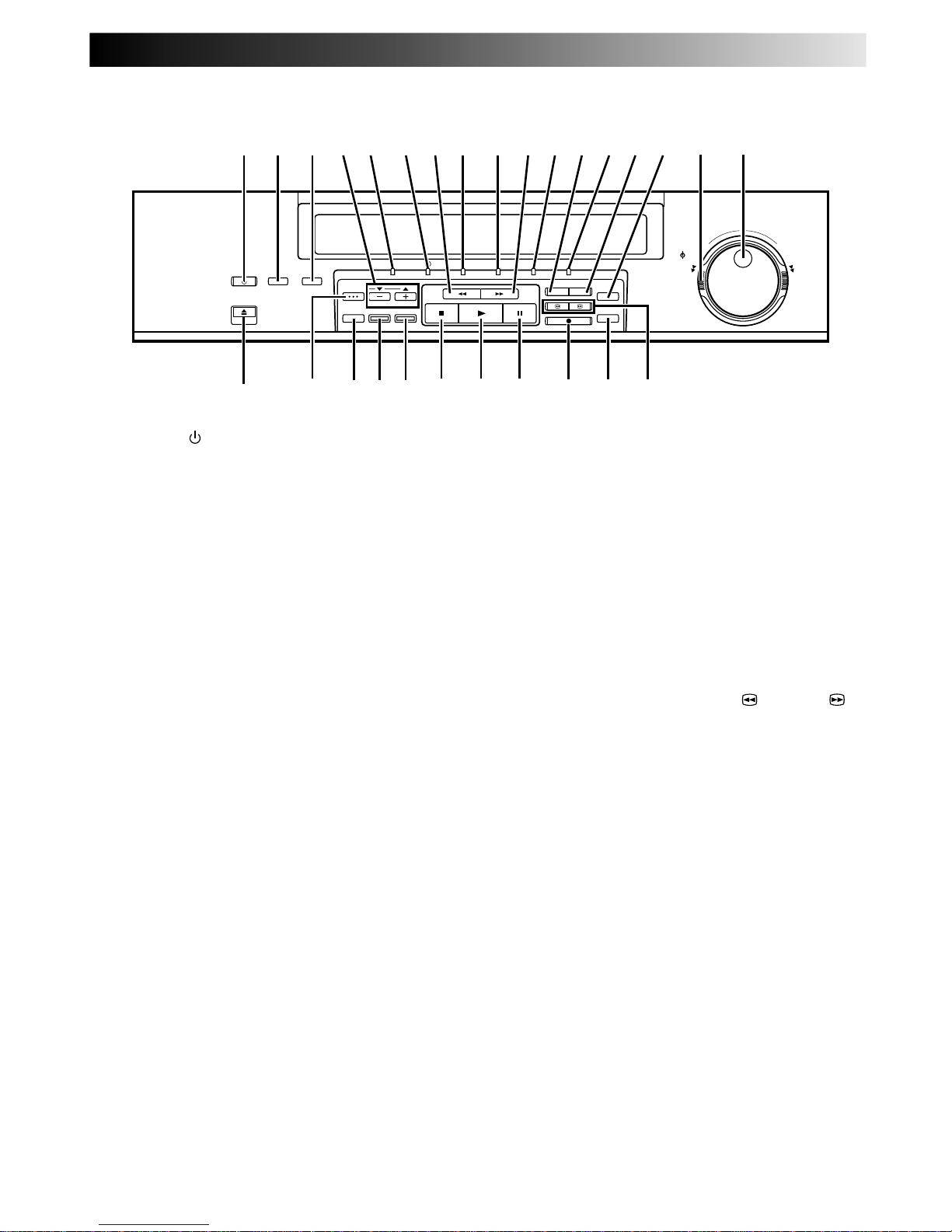
1 STANDBY Button Z pg. 8
2 SMARTPICTURE Button Z pg. 20
3 DISPLAY Button Z pg. 25
4 PROGRAMME +/– Buttons Z pg. 22
TAPE MANAGER 5∞ Buttons Z pg. 38
5 ON Indicator
6 ‰(TIMER) Indicator Z pg. 31, 33
7 Rewind [REW] Button Z pg. 15, 17
8 REC LINK Indicator Z pg. 37
9 DIGITAL TBC/NR Indicator Z pg. 19
0 Fast Forward [FF] Button Z pg. 15, 17
! STD Indicator Z pg. 22
@ REC LINK Button Z pg. 37
# LS3 Indicator Z pg. 22
$ DIGITAL TBC/NR Button Z pg. 19
% D-VHS Button Z pg. 22
D-VHS
STD/LS3
PROGRAMME /
JOG
SHUTTLE
SP/LP
R
E
W
I
N
D
F
O
R
W
D
.
ON REC LINK DIGITAL TBC/NR STD LS3
STANDBY
SMART PICTURE
EJECT
DISPLAY
TAPE MANAGER
COUNTER RESET
OK
PROGRAMME
SYNCHRO EDIT
REC LINK
INDEX
DIGITAL
TBC/NR
RECORD
ur( e
3
* t
1 2 6 7 8 90!@#$%
&^
y
i
54
)qw
^SHUTTLE Ring Z pg. 16, 17
& PROGRAMME Dial Z pg. 22
JOG Dial Z pg. 16
* EJECT Button Z pg. 15
( TAPE MANAGER Button Z pg. 38
) COUNTER RESET Button Z pg. 25
q OK Button Z pg. 9
w SYNCHRO EDIT Button Z pg. 51
e STOP Button Z pg. 15
r PLAY Button Z pg. 15
t PAUSE Button Z pg. 16
y RECORD Button Z pg. 22
u STD/LS3 Button Z pg. 22
SP/LP Button Z pg. 23
i INDEX/PICTURE SEARCH 4/ and ¢/
Buttons — same as
@ #
Button on remote
control Z pg. 16 – 18
INSIDE VIEW OF FRONT PANEL
Page 35
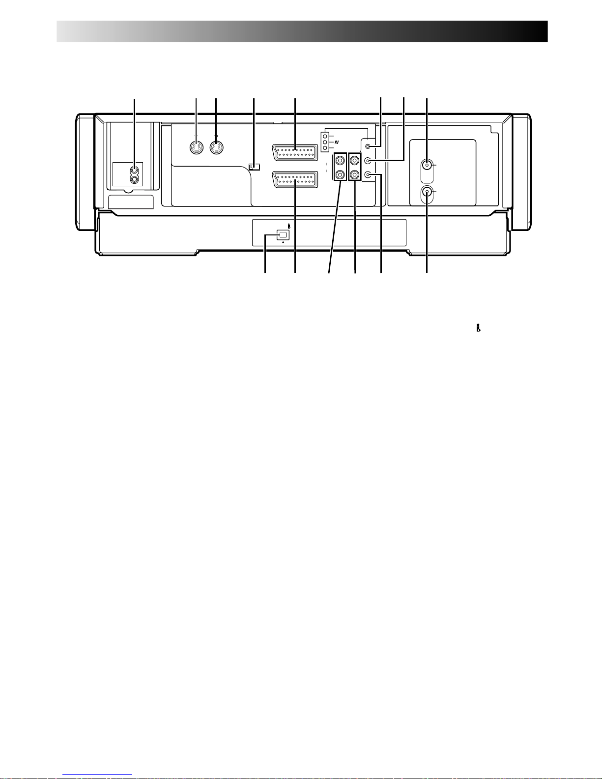
72 EN
AV1 IN/OUT
(L-1)
AV2 IN/DECODER
(L-2)
DV IN
AV1 OUT
COMP. Y/C
S IN
(S-1)
S OUT
R.PAUSE
ANT. IN
ANT. OUT
R
L
AUDIO
OUT IN
(S-1)
SYNCHRO EDIT
JLIP
1
$0 !
42 8
9
3 5
@ #
6 7
REAR VIEW
1 Mains Power Inlet Z pg. 6
2 S OUT Connector Z pg. 7
3 S IN Connector Z pg. 49
4 AV1 OUT Switch Z pg. 6
5 AV1 IN/OUT Connector
Z pg. 6, 48, 53, 54
6 SYNCHRO EDIT Connector Z pg. 51
7 J terminal [JLIP (Joint Level Interface Protocol)
Connector] Z pg. 52
8 ANT. IN Connector Z pg. 6
9 DV IN Connector (i.Link*) Z pg. 46
* i.Link refers to the IEEE1394-1995 industry specifi-
cation and extensions thereof. The
logo is used for
products compliant with the i.Link standard.
0 AV2 IN/DECODER Connector
Z pg. 48, 53, 54
! AUDIO OUT (L/R) Connectors
@ AUDIO IN (L/R) Connectors Z pg. 49
# Remote PAUSE Connector Z pg. 46
$ ANT. OUT Connector Z pg. 6
INDEX (cont.)
Page 36
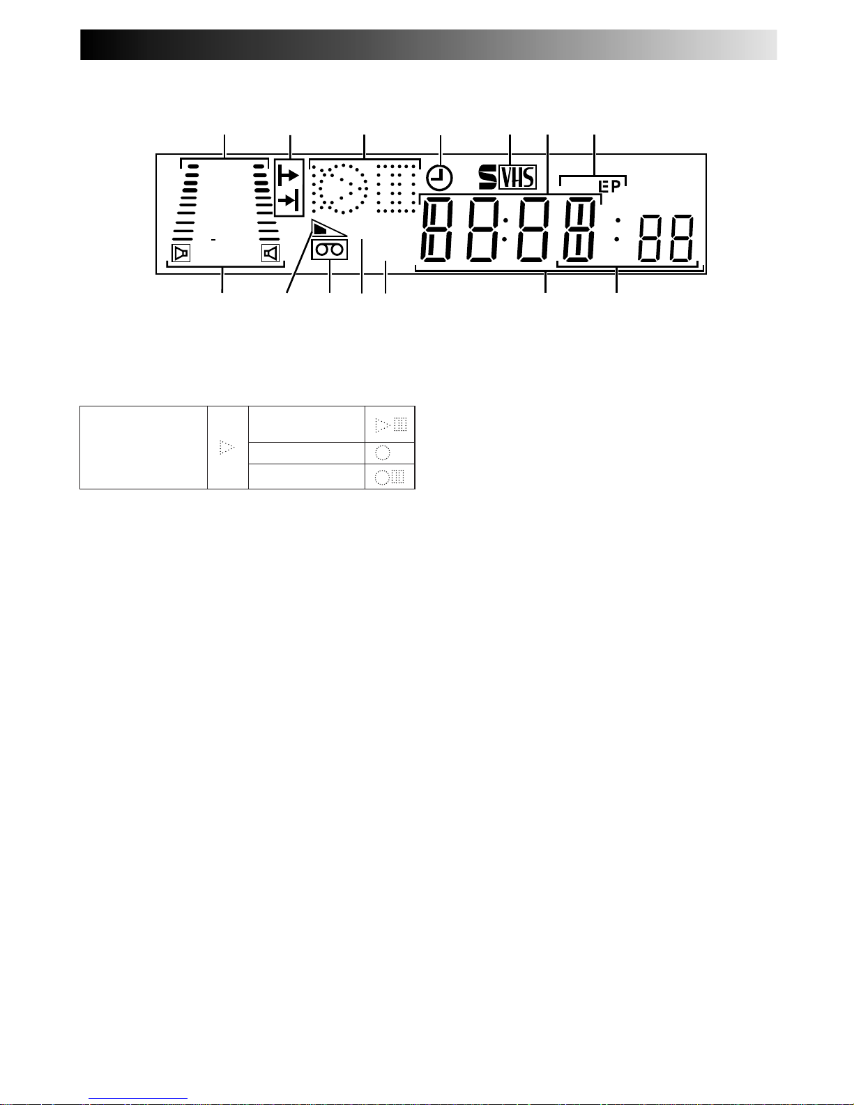
EN 73
DISPLAY PANEL
SP
VPS/PDC
VCR
+
8
4
0
6
15dB
NORM
@!
09
#
$8
1 5 6 73 42
1 DSPC System Display Z pg. 28
Audio Level Indicator
2 Programme Time Indicators Z pg. 32
3 Symbolic Mode Indicators
4 "Timer" Indicator Z pg. 31, 33
5 S-VHS Indicator Z pg. 26
6 Channel/Clock Display Z pg. 11
STILL:
SLOW:
RECORD:
RECORD PAUSE:
PLAY:
FF/REW VARIABLE
SEARCH:
7 Tape Speed Indicators Z pg. 23
* EP is only for NTSC playback
8 Audio Mode Indicator Z pg. 21
9 Tape Remaining Time Indicator Z pg. 25
0 "Cassette Loaded" Mark
! PDC Indicator Z pg. 31, 33
* VPS (Video Programme System) recording is not currently
available in the U.K. and not possible with this recorder.
@ VCR Indicator Z pg. 53
# Counter/Remain Display
(If the counter exceeds –20 hours ("–20:00:00"), the
display does not show the "–2" of "–20:00:00". In this
case, confirm the counter on the TV screen.)
$ Mode Display (I-1, L-1, L-2, F-1, S-1 or S-2)
Page 37
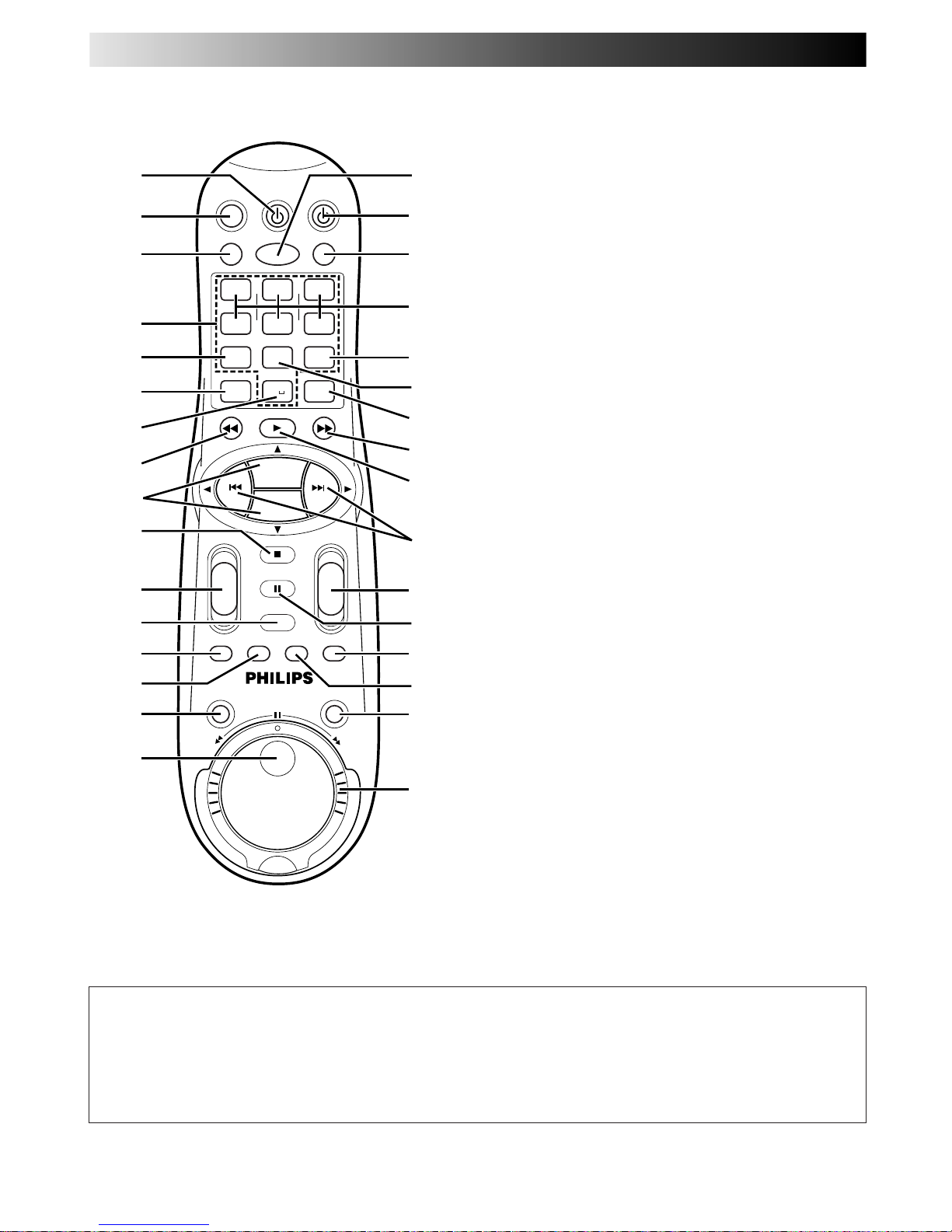
74 EN
REMOTE CONTROL
VCR
POWER
TV
POWER
VCR/TV AUDIO
PLAY
SMART PICTURE
TV CH
TV VOL
PAUSE/STILL
DISPLAY
JOG/SHTL
TIMER
MENU
TAPE
MANAGER
STOP
MUTE
1
– +
*
4
GHI
2
ABC
3
DEF
5
JKL
8
TUV
0
9
WXYZ
6
MNO
7
PQRS
START STOP DATE
VPS/PDC DAILY
PROG. +
PROG. –
WEEKLY
RECORD
-
+
-
+
SPEED CLEAR
OK
+
+
-
-
2
3
4
5
6
!
@
#
%
^
8
7
1 &
0
9
y
$
*
(
)
q
w
i
p
e
r
t
u
o
W
Q
1 TV POWER Button Z pg. 75
2 MUTE Button Z pg. 75
3 VCR/TV Button Z pg. 75
4 NUMBER Keys Z pg. 22, 30
5 PDC Button Z pg. 31, 33
* VPS (Video Programme System) recording is not currently
available in the U.K. and not possible with this recorder.
6 SPEED Button Z pg. 22, 23
7 AUX Button Z pg. 46
8 Rewind [REW] Button Z pg. 15, 17
9 %fi Buttons Z pg. 9
PROG. +/– Buttons Z pg. 22
0 STOP Button Z pg. 15, 22
! TV VOL (Volume) +/– Button Z pg. 75
@ DISPLAY Button Z pg. 25
# TIMER Button Z pg. 30, 32
$ MENU Button Z pg. 12
% JOG/SHTL Button Z pg. 16
^ JOG Dial Z pg. 16
& AUDIO Button Z pg. 21
* VCR POWER Button Z pg. 8
( SMARTPICTURE Button Z pg. 20
) START +/– Buttons Z pg. 32
STOP +/– Buttons Z pg. 32
DATE +/– Buttons Z pg. 32
q WEEKLY Button Z pg. 31, 33
w DAILY Button Z pg. 31, 33
e CLEAR Button Z pg. 30, 35, 41 – 43
r Fast Forward [FF] Button Z pg. 15, 17
t PLAY Button Z pg. 15
y
@ #
Buttons Z pg. 16
u TV CH +/– Button Z pg. 75
i PAUSE/STILL Button Z pg. 16
o TAPE MANAGER Button Z pg. 38
p OK Button Z pg. 9
Q RECORD Button Z pg. 22
W SHUTTLE Ring Z pg. 16, 17
How To Use
The remote control can operate most of your video recorder's
functions, as well as basic functions of TV sets of PHILIPS and
other brands. (Z pg. 75)
● Point the remote control toward the sensor window.
● The maximum operating distance of the remote control is
about 8 m.
NOTES:
●
When inserting the batteries, be sure to insert in the correct
directions as indicated under the battery cover.
●
If the remote control doesn't work properly, remove its
batteries, wait a short time, replace the batteries and then
try again.
INDEX (cont.)
Page 38
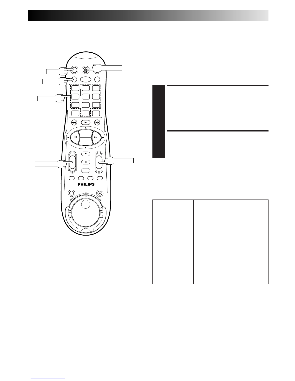
EN 75
SET TV BRAND CODE
1
Press and hold TV POWER, then press NUMBER keys
to enter your TV's brand code, referring to the table
below.
● For example, for 02, press 0 then 2.
● The remote control can now operate the TV of the
selected code.
CONFIRM SETTING
2
Press TV POWER, pointing the remote control at the TV.
If the TV turns on or off, your setting is completed.
If not, repeat steps above, using another code.
NOTES:
●
The buttons you can use to operate your TV are TV POWER,
TV CH +/–, VCR/TV, TV VOL +/– and MUTE.
●
After replacing the batteries, you need to reset the TV’s
brand code again.
Operating TV
You can use this remote control to operate your TV. To use this
remote control for operating the TV, you first need to set the
TV's brand code properly.
The default setting of the TV's brand code is "PHILIPS 01".
NOTE:
Though this remote control can operate most of the PHILIPS
TVs as well as many other manufacturers’, some of the TVs will
not operate or some functions available on the TVs will not
work with this remote control.
TV BRAND NAME CODE
PHILIPS 01, 02, 03
EMERSON 14
GOLDSTAR 04
GRUNDIG 24, 25
HITACHI 12
JVC 05
MITSUBISHI 13, 26
PANASONIC 07, 17, 19, 20
RCA 10
SAMSUNG 18
SANYO 11
SHARP 16
SONY 09
THOMSON 21, 22, 23
TOSHIBA 08
ZENITH 06, 15
1
4
2 3
5
8
0
9
6
7
-+-
+
+
+
-
-
PROG. +
PROG. –
TV POWER
TV CH +/–
TV VOL +/–
NUMBER
VCR/TV
MUTE
Page 39

76 EN
SPECIFICATIONS
GENERAL
Power requirement : AC 220 V – 240 V`,
50 Hz/60 Hz
Power consumption
Power on : 36 W
Power off : 8.7 W
Temperature
Operating : 5°C to 40°C
Storage : –20°C to 60°C
Operating position : Horizontal only
Dimensions (WxHxD) : 468 mm x 145 mm x 369 mm
Weight : 8.0 kg
Maximum recording time
D-VHS (STD) : 420 min. with DF-420 video
cassette
D-VHS (LS3) : 1260 min. with DF-420 video
cassette
S-VHS/VHS (SP) : 240 min. with E-240 video
cassette
S-VHS/VHS (LP) : 480 min. with E-240 video
cassette
VIDEO/AUDIO (D-VHS)
Format : MPEG2 standard mode
Track composition
Tape speed : 16.67 mm/sec (STD mode)
5.56 mm/sec (LS3 mode)
Head azimuth : ±30 deg
Drum rotation : 1800 rpm
Tracking system : CTL track system
Recording specification
Main data input rate: 14.1 Mbps (STD mode)
4.7 Mbps (LS3 mode)
Sub data input rate : 0.146 Mbps (STD mode)
48.7 Kbps (LS3 mode)
Recording rate : 19.14 Mbps
Track structure : 1 Sector
Length of sync block: 112 bytes
Inner ECC : RS code
Outer ECC : RS code
Code word shuffling: 6 tracks
Modulation system : SI-NRZI
VIDEO/AUDIO (S-VHS/VHS)
Format : S-VHS/VHS PAL standard
Signal system : PAL-type colour signal and CCIR
monochrome signal, 625 lines
50 fields
Recording system : DA4 (Double Azimuth) head
helical scan system
Signal-to-noise ratio : 45 dB
Horizontal resolution : 250 lines (VHS)
400 lines (S-VHS)
Frequency range : 70 Hz to 10,000 Hz
(Normal audio)
20 Hz to 20,000 Hz
(Hi-Fi audio)
CONNECTOR
Input/Output : 21-pin SCART connectors :
IN/OUT x 1, IN/DECODER x 1
CINCH connectors:
VIDEO IN x 1, AUDIO IN x 2,
AUDIO OUT x 1
S-Video connectors:
IN x 2, OUT x 1
DV connector : IN x 1
(4-pin, IEEE1394 conformity,
digital input)
TUNER/TIMER
TV channel storage
capacity : 99 positions
(+AUX position)
Tuning system : Frequency synthesized tuner
Channel coverage : VHF 47 MHz – 89 MHz
104 MHz – 300 MHz
302 MHz – 470 MHz
UHF 470 MHz – 862 MHz
Memory backup time : Approx. 60 min.
ACCESSORIES
Provided accessories : RF cable,
S-Video cable,
21-pin SCART cable,
Power cord,
Infrared remote control unit,
"R6" (AA) battery x 2,
D-VHS Cassette
Specifications shown are for SP mode unless otherwise
specified.
E.& O.E. Design and specifications subject to change without
notice.
Page 40

EN 77
A
Audio Rec Mode .........................................................27
Auto Set Up .................................................................. 8
Auto SP → LP Timer ....................................................36
Automatic Satellite Programme Recording .................. 37
Aux Input ....................................................................46
C
Cancel Timer Programme............................................34
Change Station Channel Position ................................ 59
Check Timer Programme.............................................34
Clock Setting ...............................................................64
Connection To Satellite Tuner......................................53
D
Delete Channel ...........................................................59
Digital 3R....................................................................19
Digital TBC/NR ...........................................................19
Direct Recording .........................................................13
DSPC ..........................................................................28
D-VHS Recording ....................................................... 22
DV Sound Setting ........................................................47
E
EasyLink ......................................................................13
Editing.........................................................................46
Elapsed Recording Time ..............................................25
Express Timer Programming ........................................32
F
Fine Tuning ................................................................. 60
Frame-By-Frame Playback........................................... 16
G
Guide Program Number Setting .................................. 55
H
High-Speed (Turbo) Search .......................................... 17
I
Index Search ...............................................................18
J
JLIP Terminal ...............................................................52
Just Clock ....................................................................64
M
Manual Channel Setting ..............................................58
Manual Tracking .........................................................17
N
Next Function Memory ...............................................17
O
One Touch Recording (OTR) .......................................24
On-Screen Display ...................................................... 11
Operating TV ..............................................................75
P
PDC ............................................................................33
Power Save .................................................................12
Preset Download.........................................................10
R
Recording ...................................................................22
Record One Programme While Watching Another ......24
Repeat Playback..........................................................20
Replace Timer Programme ..........................................34
S
Scrambled Broadcast...................................................59
Set Stations..................................................................61
Slow Motion Playback ................................................ 17
SmartPicture................................................................20
Soundtrack Selection...................................................21
Still Picture Playback...................................................16
S-VHS (Super VHS) ..................................................... 26
S-VHS/VHS Recording ................................................ 23
Synchro Editing ...........................................................51
T
Tape Manager .............................................................38
Delete Data .......................................................42, 43
Sorting By Category .................................................45
Sorting By Date........................................................45
Sorting By Tape Number ..........................................44
Tape Manager Functions ..........................................38
Title Editing.............................................................. 40
Tape Position Indicator ................................................ 15
Tape Remaining Time ..................................................25
Tuner Setting ............................................................... 56
TV Station And ID List .................................................62
V
Variable-Speed Search ................................................17
VIDEO Plus+
®
Setup ....................................................55
VIDEO Plus+
®
Timer Programming.............................. 30
LIST OF TERMS
Page 41

MEMO
Page 42

MEMO
Page 43

VR20D/07
3103 166 2562.1
LPT0359-001A
 Loading...