

Philips VISTA AG30 Installation Instructions Manual
INSTALLATION INSTRUCTIONS
Surgical Troffer
MODEL: AG30
CAUTION! – READ THIS FIRST --- IMPORTANT SAFETY INSTRUCTIONS
11500 Melrose Avenue
Franklin Park, Illinois 60131
Phone: 800-576-2135
Fax: 800-576-2136
www.vistalighting.com
* Carefully read the instructions pertaining to your xture.
IF YOU HAVE ANY QUESTIONS REGARDING THE
PROPER INSTALLATION OR LOCAL CODES, CONSULT
A QUALIFIED ELECTRICIAN.
* To avoid shock hazard, do not work with live electrical wires.
* Install the xture in only dry, indoor applications.
* Do not install outdoors or in applications other than the
intended use.
* Install and wire the xture in locations in compliance with
the National Electric Code and any local codes.
WARNING: THIS PRODUCT MUST BE INSTALLED IN ACCORDANCE WITH THE APPLICABLE INSTALLATION
CODE BY A PERSON FAMILIAR WITH THE CONSTRUCTION AND OPERATION OF THE PRODUCT
AND THE HAZARDS INVOLVED.
WARNING: RISK OF FIRE, MINIMUM OF 90°C SUPPLY CONDUCTORS. CONSULT A QUALIFIED ELECTRICIAN
TO ENSURE CORRECT BRANCH CIRCUIT CONDUCTOR.
WARNING: TO AVOID SHOCK HAZARD DISCONNECT THE POWER AT THE PANEL BOARD (CIRCUIT BREAKER
BOX) BEFORE BEGINNING INSTALLATION.
A. GENERAL NOTES
1. Lens Orientation
AG30 supplemental surgical xtures can be ordered with either an asymmetric or symmetric lens option. If ordered with the
asymmetric lens, the xture must be oriented with the arrows on the “Light Direction” labels pointing to the side requiring more
light – typically toward the surgical eld in the center of the room. The “Light Direction” labels can be located on the lens’
protective wrapping and/or on the inside edge of the door frame. The door-housing assembly is factory assembled as a unit.
The door assembly can not be changed in the eld to change light direction so care must be taken to orient the xture
properly during installation. For the symmetric lens option, the xture can be positioned in either direction.
2. Door Frame and Hardware
Some AG30 models utilize screws to secure the door frame to the
housing. To prevent cross-threading of the screws, start threading
each screw by hand to ensure proper threading of the screw into
end of door
frame
the nut. Once started, continue tightening the screws with a
screw driver – alternating between screws until they are all tight.
When opening or closing the door frame, support the door in the
closed position until all fasteners are completely tightened or
completely unthreaded from nut inserts.
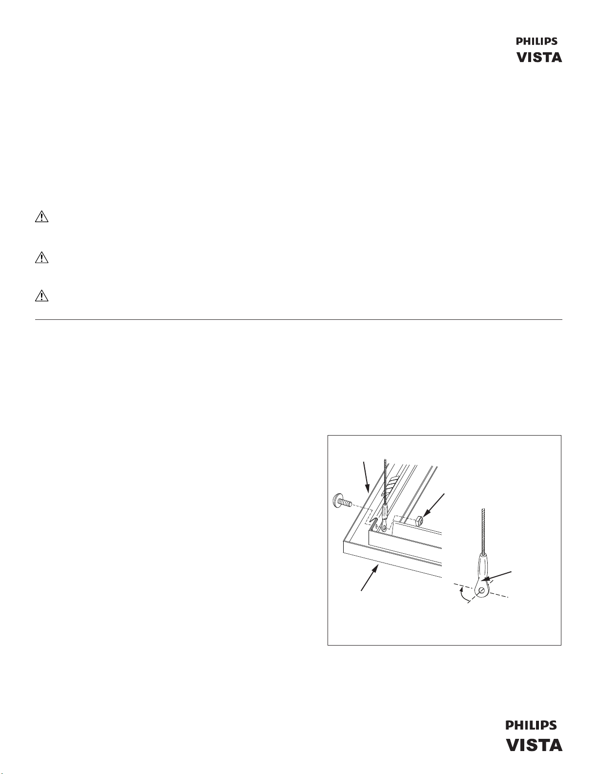
Some door frame options are supplied with a cable lanyard to
support the door in an open position. The eyelets on these cables
are secured to the housing and door frame with screws and
lock-nuts. If it becomes necessary to completely remove the door
frame from the housing, disconnect the cable from the door
frame. Follow the steps below to ensure that the cable is
reconnected properly to the door frame.
a.) Insert the screw through the hole on the door frame.
side of door
frame
The head of the screw should be near the end of the
door frame.
b.) Slide the eyelet over the screw orientating the eyelet
as shown in Figure 1. The eyelet will need to be rotated
Figure 1
90° to t properly. At other end of door rotate eyelet in
opposite direction.
c.) Tighten the lock-nut onto the screw making sure that it is loose enough for the eyelet to swivel freely. This is important to
ensure that the cable lanyard tucks away properly when the door is closed. When closing the door, always tuck the cable
lanyard inside main compartment of the xture by ipping the eyelet and cable toward the center of the door.
tighten lock-nut and then
loosen 1/4 to 1/2 turn so
eyelet moves freely
lock-nut (nylon insert)
other end of
cable fastened
to fixture
flat side
of eyelet
rotate flat side of
eyelet 90° to align
ring with hole in
door frame
B. INSTALLATION OF GRID STYLE (“G” Versions) FIXTURES
Grid style (or “G” version) AG30 Series xtures are designed to install into standard suspended grid ceilings with a standard 1" or 1½"
high grid. The AG30 grid xtures are sized to t within standard 2x2 and 2x4 ceiling systems. Fixtures can be installed in any pattern
necessary within the ceiling grid layout. The weight of the xture is supported by the grid and supplemented with direct connection to
the building AG30ucture. The steps for installation are as follows:
1. Inspect the ceiling grid to make sure it is supported from the building structure as recommended by the ceiling grid manufactuer's
instructions. This must be approved before bearing the weight of the lighting xture.
2. Angle the xture up through the opening in the grid making sure that the door frame is facing the room. Once the xture is
positioned through the opening, it can be leveled out and lifted down until the anges of the xture rest on the corresponding
anges of the ceiling grid. For 2x2 xtures being installed within a 2x4 ceiling system or for 1x4 xtures, additional grid pieces
may need to be installed. All four sides of the xture must rest on the grid.
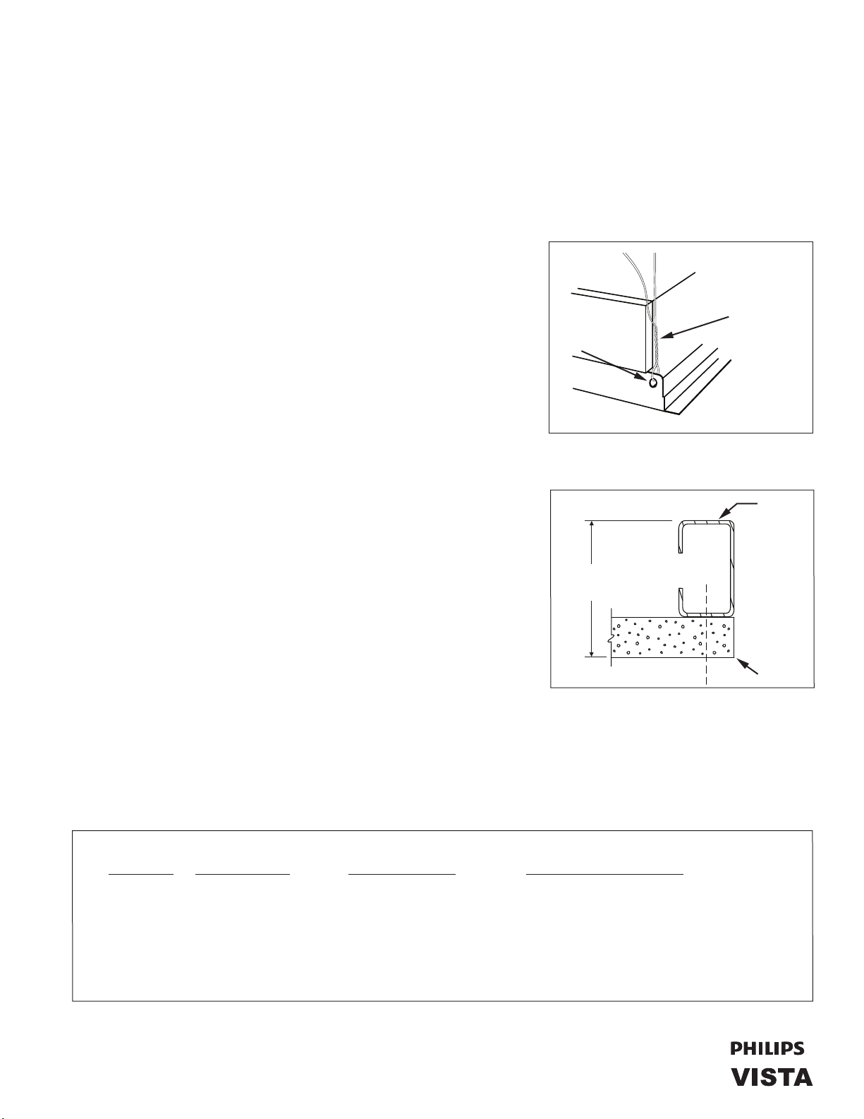
3. The xture is to be connected directly to the building structure, independent
of the ceiling grid. Locate the hanger support tab at each corner of the xture
as shown in Figure 2. Use a hanger wire at all four support tabs to tie the
xture to the building structure. Use 12 gauge minimum hangar wire rated
for such application. In addition, follow local building codes regarding
required additional support of xtures.
Retainer Clips or Earthquake Clips can be ordered as accessories with the
hanger
suPPorts
hanger
suPPort
tab
wire hanger
1 at each
corner
(by others)
AG30 Series xtures for additional support with grid ceilings. When using
these accessories, the xture should still be installed per the instructions
above. Specic instructions for installing and using these accessories are
supplied with the packaging for the clips.
4. Follow the instructions in section “E. Making Electrical Connections”. If the
xture has an emergency ballast and/or dimming ballasts, also follow the
instructions in sections “F. Emergency Ballast Connections” and “G. Low
Figure 2
t grid not shown
Voltage Dimming Circuits”.
C. INSTALLATION OF AN INDIVIDUAL FLANGED (“F” Version) FIXTURE
Flange style (or “F” version) AG30 Series xtures are designed to install into dry
wall (i.e. gypsum board, sheetrock) ceilings. It is important to carefully review
and follow the instructions in this section to ensure a successful installation.
1. Determine the required ceiling opening.
Installation requires a clean and accurate opening to be cut into the ceiling
min. 1-1/16"
max. 3-1/16"
rigid
framing
around
ceiling
oPening
surface for the xture to be installed into. Openings need to be cut square
and accurate to 1/16" of the provided dimensions. The cut openings should
be into whole pieces of ceiling material to minimize seams and joints inter-
secting the cut opening. This limits the stress on taped joints and ensures a
better t of the xture ange against the ceiling surface.
The ceiling surface should be free of bowing and the area around the ceiling
opening should be nished to a smooth and at surface free of imperfections.
Figure 3
edge
of
oPening
The elevation of the ceiling surface should not deviate more than 1/32" over 2'
of horizontal surface.
Rigid framing (i.e. C-channel) around the cut opening should be installed with the inside edge of the frame positioned ush
with the cut opening. The ceiling material should be secured to the bottom surface of the frame. The combined thickness of
the ceiling material should be a minimum of 1-1/16" but no greater than 3-1/16". (See Figure 3)
The ceiling opening for individual xtures are listed in Chart 1 below.
Nominal Fixture Required Ceiling Required Ceiling Opening
Model Size Opening
(when using Plaster Frame*)
AG30F24 2' x 4' 22-7/8" x 48-5/8" 23" x 48-3/4"
AG30F22 2' x 2' 22-7/8" x 24-5/8"** 23" x 24-3/4"**
AG30F14 1' x 4' 10-7/8" x 48-5/8" 11" x 48-3/4"
* The Plaster Frame kit is packaged separately from the xture with installation instructions.
** The 24-5/8" dimension (or 24-3/4" when using a Plaster Frame) represents the length of the opening running parallel to the side ange
(or lamps) of the surgical xture.
Chart 1
2
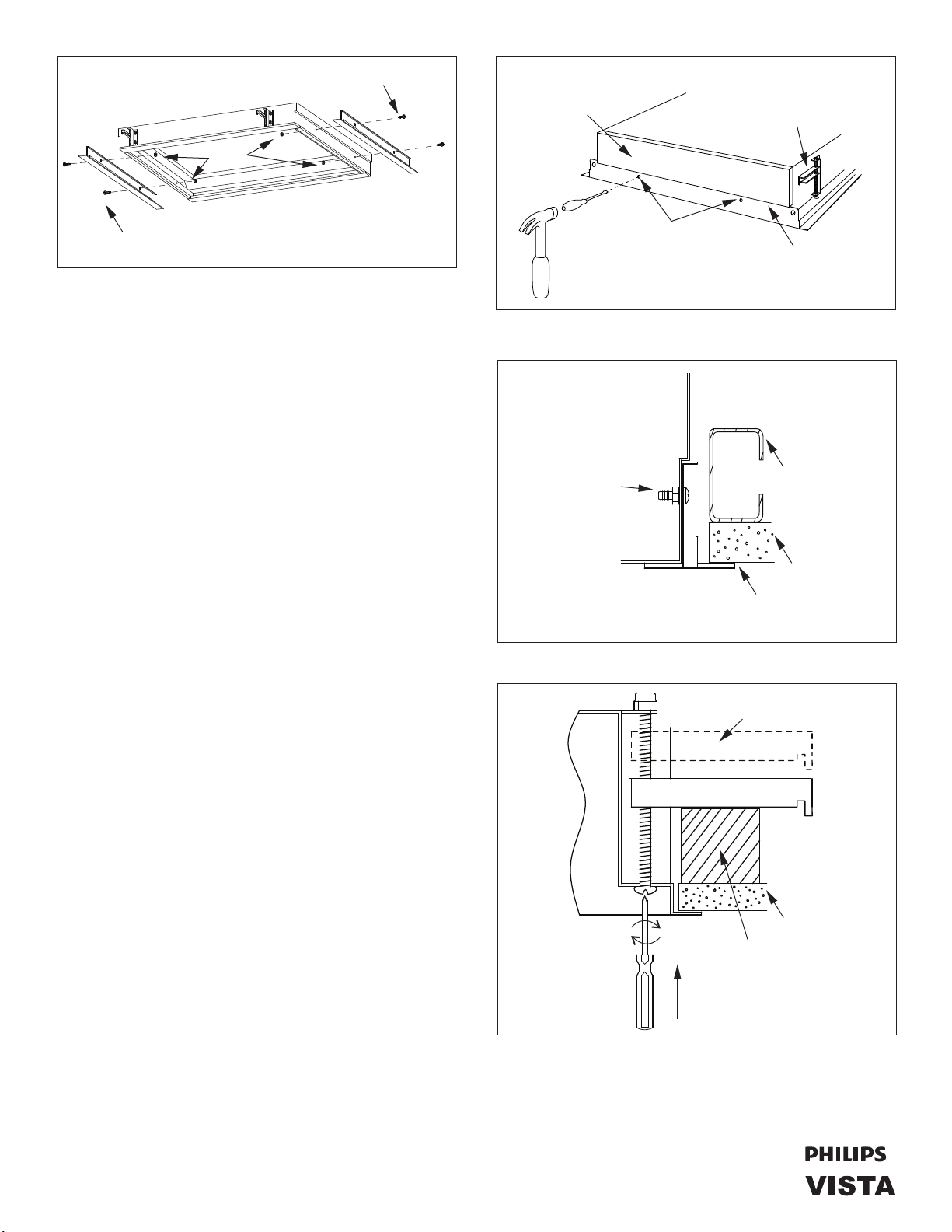
nuts
screws
housing
endPlate
keeP sway hanger
against housing
during insertion
into ceiling
screws
Figure 4
2. The AG30 anged xture has been supplied with two
end trims that need to be installed on the xture before
securing it to the ceiling. The trims pieces are secured
to the end cap of the xture as shown in Figure 4. (The
end cap can be identied by its offset prole.)
Install trims by locating the two mounting hole knock
outs and use a pointed tool and hammer to push in and
breakout all the knockouts from each of the xture
endplates. (See Figure 5) Position the trim piece so
that its center spline rests against the end cap (as
illustrated in Figure 6) with the mounting holes aligned
with the holes in the end cap. Insert the screws through
the trim piece and through the end cap from the outside
of the xture. Thread the nut onto the screw and tighten.
Repeat this step on the other end of the xture.
3. Check to make sure the sway bracket hangers, mounted
on the outside walls of the xture (See Figure 5), are
resting against the side of the xture. Carefully lift the
xture resting it on a support surface just below the ceiling.
4. Follow the instructions in section “E. Making Electrical
Connections” before beginning Step 5 below. If the xture
has an emergency ballast and/or dimming ballasts, also
follow the instructions in sections “F. Emergency
Ballast Connections” and “G. Low Voltage Dimming
Circuits”.
5. Once the conduit is connected to the xture, you can lift
the xture through the ceiling opening. The door of the
xture will need to be opened to gain access to the sway
bracket adjustment screws. Turn these screws in a clock
wise direction to swing the wing of the sway bracket out
from the xture as shown in Figure 7. When this has been
done at all four of the sway brackets the xture can
support itself on the framing around the opening.
7. Continue turning the sway bracket adjustment screws
clockwise, alternating between locations, until the xture
ts snug against the ceiling. Make sure the end trim
ts against the ceiling as shown in Figure 6.
8. If the xture has an emergency ballast and/or dimming
ballasts, follow the instructions in sections “F.
Emergency
Ballast Connections” and “G. Low Voltage
Dimming Circuits”.
remove knock outs
on end trims for
flange mounting
Figure 5
housing
install
screw
from
outside
(nut inside)
end trim
ensure end trim gaskets are in good
contact with fixture housing and
ceiling at locations indicated
Figure 6
turn clockwise
to swing out
and lower bar
turn counter
clockwise to
raise bar
Figure 7
offset in
endPlate
ceiling oPening
suPPort
ceiling
make gasket
contact here
hanger bars
ceiling
ceiling suPPort
insert
screwdriver
uP into
access hole
3
 Loading...