

Page 1
Eng
F
D
E
NL
I
P
DK
SU
N
S
GR
VCM7D130/00T & VC7D1305T
REO Series
Color Dome Cameras
Installation Instructions
Philips
Communication
Security & Imaging
Page 2

Page
English ....................................................................................................................3
French ....................................................................................................................9
German..................................................................................................................14
Spanish ..................................................................................................................19
Dutch ....................................................................................................................24
Italian ......................................................................................................................29
Portuguese............................................................................................................34
Danish ....................................................................................................................39
Finnish ....................................................................................................................44
Norwegian ............................................................................................................49
Swedish..................................................................................................................54
Greek ....................................................................................................................59
2
Page 3
IMPORTANT SAFEGUARDS
1. Read these instructions.
2. Keep these instructions.
3. Heed all warnings.
4. Follow all instructions.
5. Do not use this apparatus near water.
6. Clean only with dry cloth.
7. Install in accordance with the manufacturer’s instructions.
8. Do not install near any heat sources such as radiators, heat registers, stoves, or other
apparatus (including amplifiers) that produce heat.
9. Protect the power cord from being walked on or pinched particularly at plugs, convenience
receptacles, and the point where they exit from the apparatus.
10 Only use attachments/accessories specified by the manufacturer.
11. Unplug this apparatus during lightning storms or when unused for long periods of time.
12. Refer all servicing to qualified service personnel. Servicing is required when the apparatus
has been damaged in any way, such as power-supply cord or plug is damaged, liquid has
been spilled or objects have fallen into the apparatus, the apparatus has been exposed to rain
or moisture, does not operate normally, or has been dropped.
13. To reduce the risk of fire or electric shock, do not expose this apparatus to rain or moisture.
14 The apparatus shall not be exposed to dripping or splashing.
15 Do not install this equipment in a confined space such as a bookcase or similar unit.
WARNING
This device is intended for use in public areas only. Surreptitious recording of oral
communications is strictly prohibited by US Federal law. The manufacturer recommends posting
obvious signs to warn that oral communications are being recorded.
FCC INFORMATION
This equipment has been tested and found to comply with the limits for a Class B digital device,
pursuant to Part 15 of the FCC Rules. These limits are designed to provide reasonable protection
against harmful interference in a residential installation. This equipment generates, uses and can
radiate radio frequency energy and, if not installed and used in accordance with the instructions,
may cause harmful interference to radio communications. However, there is no guarantee that
interference will not occur in particular installation. If this equipment does cause harmful
interference to radio or television reception, which can be determined by turning the equipment
off and on, the user is encouraged to try to correct the interference by one or more of the
following measures:
■ Reorient or relocate the receiving antenna.
■ Increase the separation between the equipment and receiver.
■ Connect the equipment into and outlet on a circuit different form that to which the receiver
is connected.
■ Consult the dealer or an experienced radio/ TV technician for help.
3
Eng
ATTENTION: INSTALLATION SHOULD BE PERFORMED BY
QUALIFIED SERVICE PERSONNEL ONLY IN ACCORDANCE WITH
THE NATIONAL ELECTRICAL CODE OR APPLICABLE LOCAL
CODES.
Page 4

Servicing: Do not attempt to service this product yourself as removing covers expose
you to dangerous voltage or other hazards. Refer all servicing to qualified service
personnel.
Damage requiring service: Unplug this product from the wall outlet and refer
servicing to qualified service personnel.
Replacement Parts: When replacement parts are required, be sure the service
technician has used replacement parts specified by the manufacturer or have the same
characteristics as the original part. Unauthorized substitutions may result in fire,
electric shock, or other hazards.
Safety Check: Upon completion of any service or repairs to this product, ask the
service technician to perform safety checks to determine that the product is in proper
operating condition.
1. INTRODUCTION
This Dome camera is designed for use with REO Observation Systems only. It
combines a high sensitivity sensor with advanced digital signal processing, resulting in
a high quality Dome camera with excellent performance even under difficult
circumstances.
2. STANDARD PACKAGE INCLUDED
- Screws x 2pcs
- Dome camera x 1pc
- Dual twisted pair cable - 15 metres x 1pc
- DFU x 1pc
3. INSTALLATION (Refer to Fig. 1)
To obtain the best results from your new Dome camera, read these instructions
carefully before use. Retain the manual for future reference. Recommended for indoor
Application Only
This chapter describes the installation of the Dome camera. For more detailed
information about the installation and operation of the system monitor you should
consult the monitor manuals.
Remark: When the system configuration is altered, the system monitor needs to check and
memorise the cameras and accessories connected to its inputs. This is done automatically
when the mains power is switched on (rear switch).
4
Eng
Page 5
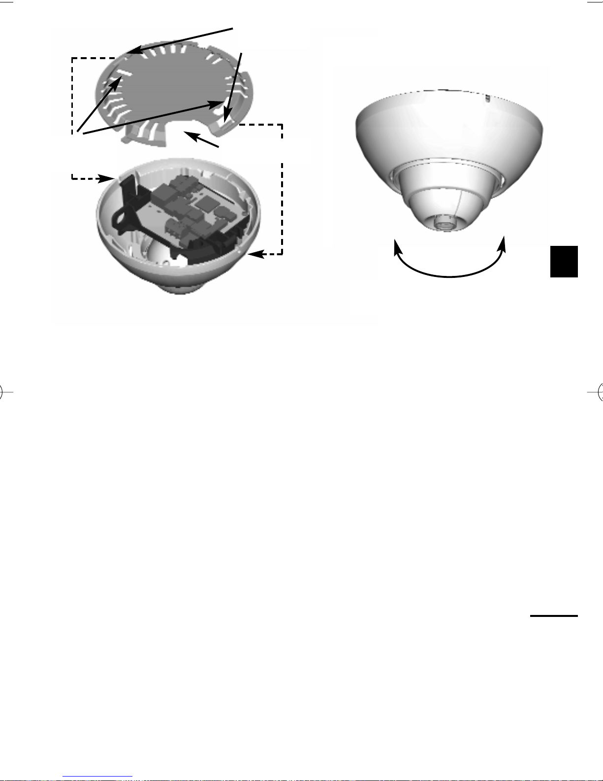
Case a: Cables’ route is above the ceiling
Case a: Remove the mounting plate by pushing the side tabs.
Drill two holes (≥ 3mm [0.19-inch]) for camera mount; and one (1) go-through hole
(≥ 8mm [0.31-inch]) for cables entry. (See template).
Case b: Cables’ route is on the wall
Case b: Remove the mounting plate by pushing the side tabs.
Drill two holes (≥ 3mm [0.19-inch]) for camera mount only. (See template).
1. Route the cables through the mounting plate, and then mount the plate using
the two supplied screws.
Locate cable into the appropriate routing clip
a. For through connection (ceiling mount).
b. For direct connection (wall mount).
2. Locate the Dome camera onto the mounting plate.
3. Connect the Dome camera to the system monitor.
4. Connect the system monitor to the mains.
5. Switch on the mains power switch.
The monitor will check the system. After a short time the Dome camera image
will appear on the monitor screen.
6. If necessary adjust contrast /brightness and/or color (See the View Settings
5
Eng
Fig. 1
120º Horz; 120º Vertical;
360º Rotation
Push in
Cable entry
Mounting
Slots
Page 6
menu of the monitor) to optimize the image on the system monitor.
7. Remove the tinted dome cover by pressing and pulling.
8. Hold the Dome camera at the proposed installation position.
9. To make sure the image on the monitor is the right way up.
Case a (ceiling mount): Make sure the lens is pointing away from the
Philips logo, before rotating it into the preferred direction.
Case b (wall mount): Make sure the lens is pointing at the Philips logo
before rotating it into the preferred direction.
Note: When the minidome camera is unpacked, the default position of the
camera image is with the top of the image at the Philips’ logo side.
10. Check the monitor to ensure the Dome camera covers the required area. (The
best results are obtained when the Dome camera is not looking into a bright
light source).
11 If necessary adjust the focus ring of the integrated Dome camera lens to obtain
optimal image sharpness .
Caution: Never touch the glass of the camera lens as this may cause damage.
12. Fit the tinted dome cover.
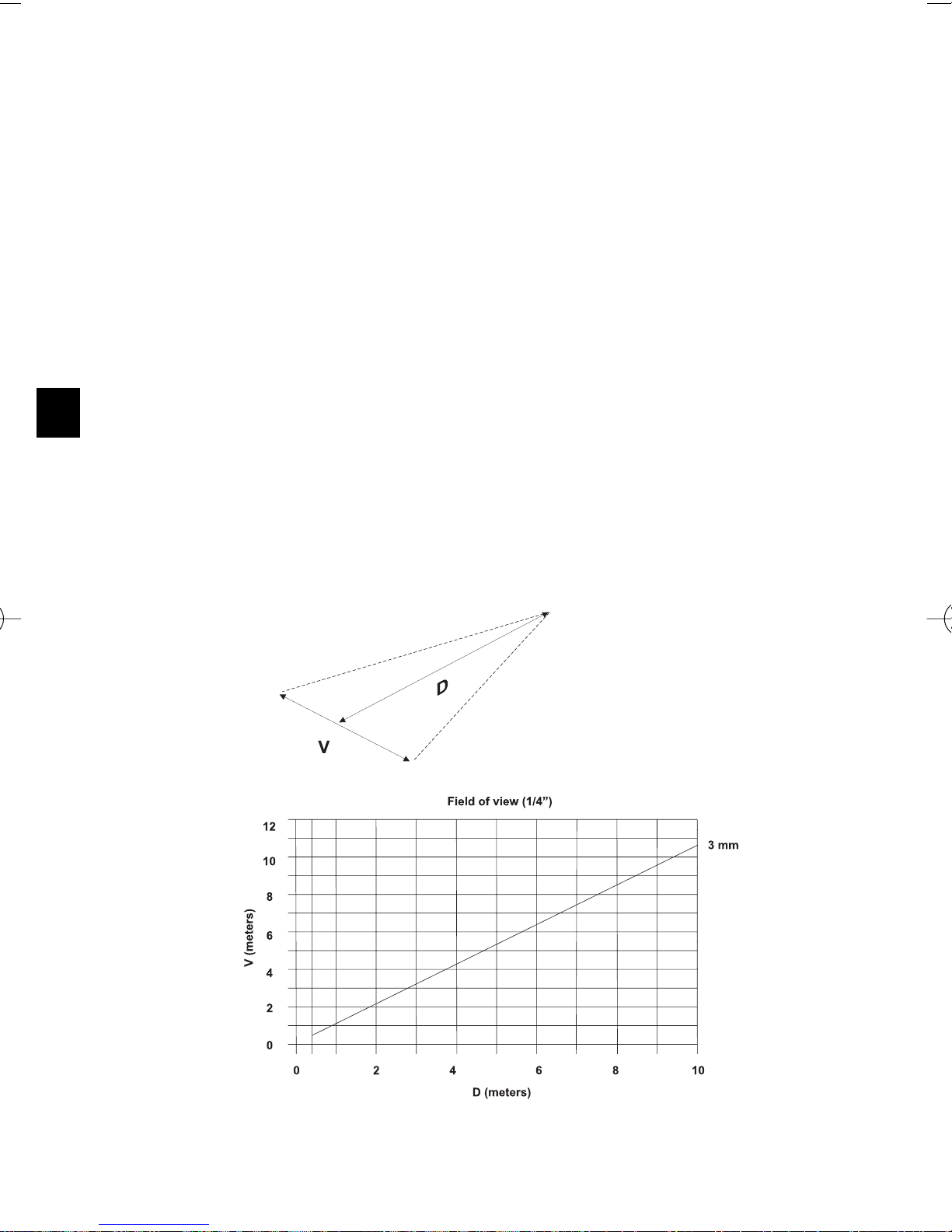
Field of view
The figure below shows the Field of view
Dome camera sound on/off
Use the On Screen Display Menus of your system monitor to enable or disable the
built-in Dome camera microphone.
6
Eng
Page 7
System Cable
For the interconnections between the system monitor and Dome camera 15m/45ft
system cable is supplied.
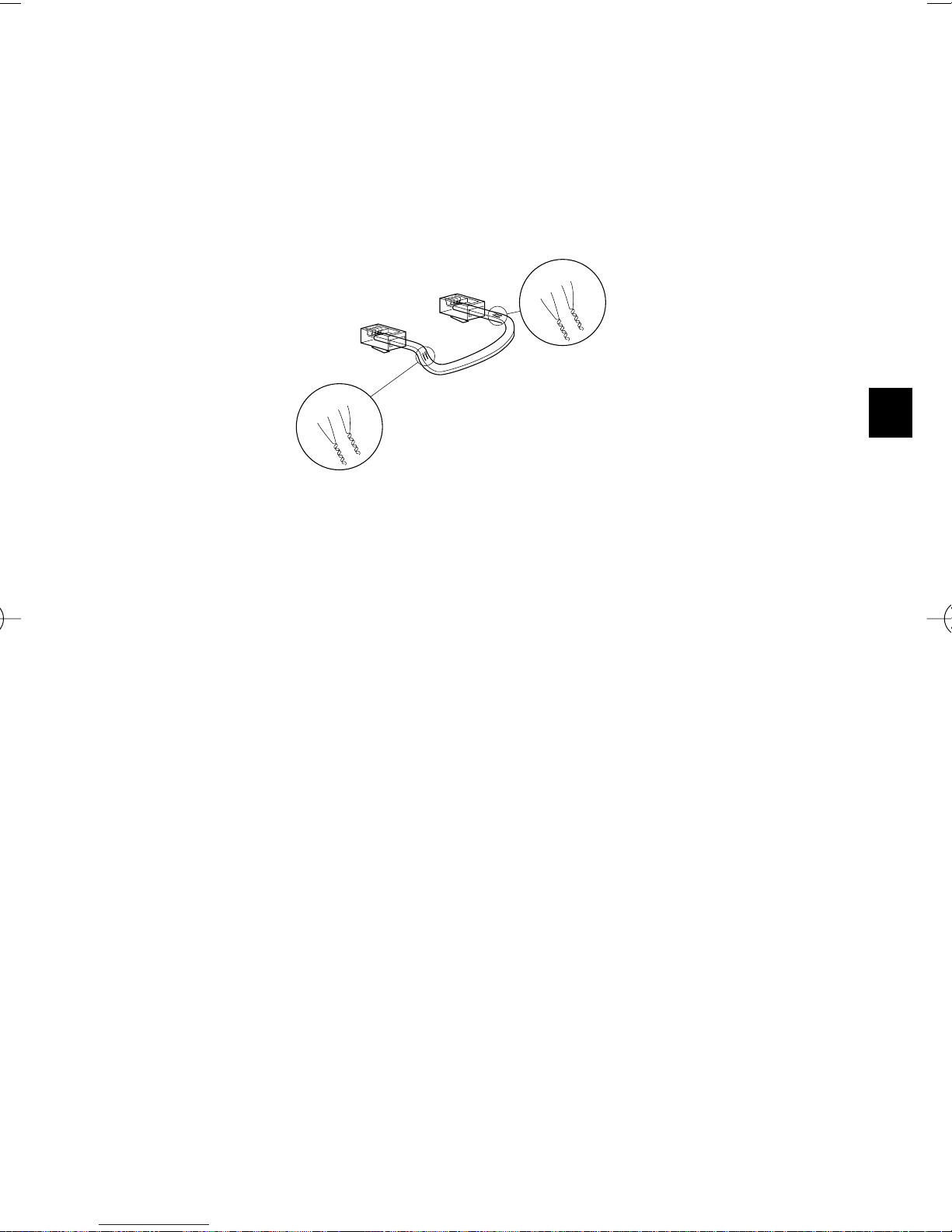
For an optimum picture and sound quality you should always use 4-wire dual
twisted-pair cable when extending the connection. The maximum allowed cable
length is 200m/600ft.
Pay attention that the connectors are fixed to the cable corresponding to the figure.
Caution: The plugs used for the observation system have the same dimensions as standard
telephone plugs. Never connect a telephone to the Dome camera or system monitor.
4.TIPS FOR MAINTENANCE
Cleaning
You can clean the outside of the Dome camera with a moist fluff-free cloth or
shammy leather cloth.
When cleaning the Dome camera lens a special cleaning cloth should be used. Do
NOT use cleaning fluids based on alcohol, methylated spirit, ammonia, etc..
Never touch the glass of the Dome camera lens to prevent its delicate coating from
damaging.
Avoid direct contact with water.
5. SPECIFICATIONS
VCM7D130/00T PAL Integrated lens
VC7D1305T NTSC Integrated lens
Accessories
The following Dome camera accessories are available:
• Extension system cables (loop resistance max. 16 Ω at 100m).
• Cable extension box for providing additional power and cable length
compensation to the Dome camera at large distances (up to 300m).
7
Eng
5
4
2
3
4-5
2-3
2
3
2-3
5
4
3
2
5
4
3
2
5
4
4-5
Page 8

Electro Magnetic Compatibility (EMC)
This equipment complies with the European EMC directive used standards:
EN50130-4, EN55022
USA standard: FCC part 15, class B
Australia AS/NZS 3548
Safety
according to European standard EN60065 ; USA UL6500
Environmental conditions:
Operating temperature -10°C +45°C
Non operating temperature -25°C +70°C
Relative humidity Non-condense 0% to 95% RH
Input Voltage, via tp-input: 24VDC
Power consumption, Typical 2.5W
Weight 0.31 kg
Dimensions Ø 115 mm h = 80 mm
This camera can be connected to a previous generation Color Observation System
Monitor at a length of 15 meters. By using an interface box for every camera the
cable length can be up to 200 meters.
If you have any problems, contact your dealer.
8
Eng
Page 9

3122 165 22073 01-43 © 2001 Philips Electronics N.V.
Data subject to change without prior notice.
 Loading...