

Page 1
gMfifg©
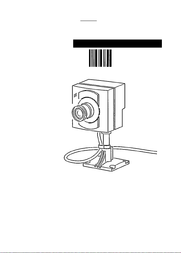
Observation Camera
VCM9175/00T/VCM91 76/oot
oiiaoQoa oas979
User manual
PHILIPS
Page 2

ENGLISH
FRANÇAIS
.................
..............
......
......
1
9
ESPAGNOL
PORTUGUÉS
NEDERLANDS
DEUTSCH
ITALIANO
DANSK....................
SVENSKA
NORSK
SUOMI.....................
TECHNICAL
SPECIFICATION
............
.........
------
...............
...............
...............
...................
....
....
....
__
....
....
....
....
....
....
....
18
27
36
45
54
63
71
80
89
99
Page 3
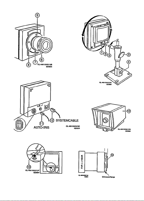
Figure A
Page 4

Page 5

Observation Camera
ENGLISH
This device complies with part 15 of the FCC ruies. Operation is subject
to the following two conditions:
1. this device may not cause harmful interference, and
2. this device must accept any interference received, including
interference that may cause undesired operation.
This device is intended to be attached to a receiver that is not used to
receive over-the-air broadcast signals. Connection of this device in any
other fashion may cause harmful interference to radio communications
and is in violation of the FCC Rules, Part 15.
This device complies to FCC rules under test conditions that included
use of system cables and connectors between system components. If
you have any problems, contact your dealer.
WARNING:
To prevent fire or shock hazard, do not expose this camera to rain or
moisture. Do not attempt to disassemble the camera. In order to
prevent shock and fire hazard, do not remove screws or covers. There
are no user-serviceable parts inside.
The illustrations to which this manuai
refers, are shown on the front and
back jacket flap.
Page 6

Table of contents
Page
Introduction
Installation
Tips for maintenance-
................
.................
Sound
Position
Protective cover
Video out
The lens
Cable
introduction
Your new CCD camera is specially developed for use with a special
observation system monitor.
It features a sensitive microphone thus registering both images and
sound via the monitor.
Installation
Warning:
When a camera or accessory is connected or disconnected,
the monitor should always be disconnected from the mains
supply.
Only operating the stand-by key is not sufficient.
When the mains supply is connected, ail camera lines are scanned.
The monitor uses this to register the camera configuration of the
system and to check whether any modifications have been made.
Page 7

Sound
If required, the microphone incorporated in the camera, can be
switched off, (fig. A-13).
If an Intercom box is included in the camera line, the sound of camera
and intercom box wiil be reproduced by the monitor.
Position
First you need to determine where the camera is to be installed. The
best results are obtained when the camera looks a little downwards and
not into a bright source of light.
• Hold the camera In your hand at the spot where you want to Install
it and check on the monitor whether the camera does actually cover
the required area from that spot.
• Fasten the mounting bracket to the ceiling, the wall, or another
even and firm surface by means of the supplied screws and plugs.
• Tighten the knob (fig. A-3) of the ball-and-socket joint.
• Fasten the camera to the bracket by screwing the mounting hole in
the back or bottom of the camera (fig. A-1) onto the threaded end
(fig. A-2).
• Loosen the knob of the ball-and-socket joint (fig. A-3) and, if neces
sary, the screw (tig. A-4) on the mounting bracket and direct the
camera accurately at the object or area you want to have on screen.
• The knob and screw can be tightened again when the camera is in
the required position.
Remark: The camera can also be mounted on any other camera tripod
standardly provided with a V4'20 UNC thread.
Protective cover
For outdoor use a protective cover (fig. A-10) (optional) has to be used
to protect the camera from rain and snow.
Video out
Connect the system cable to the output of the camera (fig. A-12).
Page 8

The lens
Caution: Do not touch the glass of the lens. This could damage the
delicate coating on its surface, if the lens has to be cleaned, use a
special lens cleaning tissue, available at any good camera store.
Focus range: The camera supplied with a CS-mount lens does have a
manual focus adjustment. This allows you to find an optimal image
sharpness for objects between 0.3 metre and infinity by rotating the
front ring with the text FAR NEAR. You should be aware that the
most FAR position does not always gives you the best image
sharpness for an object far away.
Using a different lens: The CS-mount of the camera allows you to use
any one of a wide range of both C-mount and CS-mount lenses with
a fixed-iris or manual-iris mechanism. When choosing a C-mount
lens you should use a C/CS adapter ring. An auto-iris connector at
the back of the camera (fig. A-11) enables you to choose for a
passive (or DC-controlles) auto-iris lens.
Caution:
The back side of a CS-mount lens (fig. A-14) should not protrude more
than 6mm outside the flange of the CS-mount (11mm for a C-mount
lens) otherwise the lens might touch the filter glass in the camera.
You may want to use a lens with a different angle of view and thus a
different focal length than the lens supplied with your camera. The next
diagram will help you select the focal length, required to cover the ob
ject of area you want to be monitored. It shows the width of the scene
visible on the screen with lenses of different focal lengths at given
distances (camera to object). You can extend the scope of the diagram
by simply mulitplying the values at both axes with ”x".
Page 9

8 10
s 8
Distance object to camera In metres
Example;
If the distance camera to object is 21 metres: simply mulitply the value
distance camera to object for 7 metres with 3. Next multiply the width of
the scene, reproduced on the monitor screen by 3 also.
The choice of a lens may affect the sensitivity of your camera. Consult
the table below to see which type of lens is required for your particular
application.
F-value
of lens
1.2 1
1.4
1.6
1.8
2.0
2.8
Sensitivity
(lux)
1.25
1.6
2
2.5
5
Page 10

The given sensitivities are vaiid for a common lens transmission of 80%
and a scene reflection of 75%. In case of an auto-iris lens the maximum
illumination level is far more than 100,000 lux {direct sunlight). The
apperture of the lens will automatically close when used in a high-light
environment.
Automatic iris lenses;
Note: When the camera is used outdoors for longer periods of time
(high-light environments) the use of auto-iris lenses is recommended.
The aperture of a passive auto-iris lens is DC-controlled via the
4-poIe auto-iris connector at the back of the camera (fig. A-11).
The pin connections of this auto-iris connector is:
pin 1 = control coil pin 2 = control coil +
pin 3 = driving coil +
pin 4 = driving coil -
The auto-iris lens cable should be provided with a 4-pole plug to
match. Recommended lens cable plugs are;
Chuomusen type E4-191J-100 or E4-151J
Changing lenses: Remove the old lens by turning it counter-clockwise.
While unscrewing the lens you should not release the back-focus
locking ring (fig. A-9) otherwise you may have to readjust the
back-focus of the camera.
Mount the lens by turning it clockwise onto the lens mount of the
camera. In case of a C-mount lens you first need to mount a 5mm
spacer (C/CS adapter ring).
When an auto-iris lens is mounted, connect the lens cable to the
auto-iris connector at the back of the camera (fig. A-11).
Point the camera at the object to be monitored and adjust the manual
focus of the lens (if present) for an optimal image sharpness.
Page 11

Caution:
The CCD sensor in the camera is sensitive to dust, if you remove the
iens from the camera you shouid always point the camera downwards
to minimize possible deposit of dust. Never touch the sensor and/or use
any cleaning materials. Only use clean, dry air to blow any particle form
the surface of the sensor.
When using a manual-iris lens, you should, in principle, set it at its
largest aperture. You may however reduce the lens aperture a few stop
when the camera is used in a high light intensity environment or when
an increased depth of field is required. This smaller lens aperture
affects the sensitivity of the camera (see before mentioned table).
Most lens mounts of auto-iris lenses are rotabtable so you can adjust
the lens in a desired position without loss of sharpness.
Back-focus adjustment; Adjustment of the back-focus distance of the
camera is necessary when the backfocus locking ring has been
released of when a particular lens gives an unshap image.
• Set the manual focus adjustment ring of the lens (if present)
(fig. A-6) to the FAR position or at infinity.
• Set the manual- iris (if present) to its largest opening.
• Aim the camera at an object at least 15 metres / 45 ft away.
• Loosen the back focus locking ring (fig. A-9) by turing it
counter-clockwise.
• Rotate the lens, including the CS-mount ring (fig. A-8), untill the
video-image on the monitor is sharp.
• Keeping the lens in place, tighten the back-focus locking ring by
turning it clockwise.
Note:
In case of an auto-iris lens:
• The back-focus adjustment is most accurate with the iris set to its
largest aperture, so it is recommended to do this adjustment
indoors under normal (reading) light circumstances without bright
Page 12

lightsources positioned withing the field of view of the camera, if not
possible you may also use some Neutral Density filters to reduce
the illumination level of the camera.
• The lens cable of an auto iris lens prevents the lens being rotated
more than 360°. In case it should be necessary, disconnect the iris
cable, rotate the lens 360°, reconnect the iris cabel and continue
the back-focus adjustment.
Cable
A 4-wire system cable (see specifications) is supplied standardly.
For an optimum picture and sound quality a standard ’twisted-pair”
(telephone) cable should be used.
There is an extensive range of plugs and tools available in the hobby
and professional trade to extend the cable. Always pay attention that
the connection corresponds to figure B.
Remark: Used system cables and connectors are similar to the ones
used for telephone, but may not be interconnected.
The maximum distance that can be bridged (without a cable extension
adapter) between the monitor and the cameras amounts to 200 meters
(150 meters for colour).
Tips for maintenance
Cleaning: The outside of the camera can be cleaned with a moist
fluff-free cloth or shammy leather cloth.
When cleaning the objective a special lens cleaning
cloth should be used. Do NOT use cleaning fluids
based on alcohol, methylated spirit, ammonia, etc..
Avoid direct contact with water.
Page 13

98
Page 14

99
Page 15

100
Page 16

Technical specification
CCD CAMERA
Pick-up device
No. of picture eiemenls (H) x (V)
Horizontal resolution
Light sensitivity
Spectral sensitivity range
Signal to noise ratio
White balance
Output AN
Built-in microphone
Lens type
Lens viewing angle
focal length
relative aperture
focus range
Power supply
Power consumption
System cable
Tripod socket
Dimensions (WxHxD)
Weight
Ambient conditions
temperature (Operating/Storage)
humidity (Operating/Storage)
PROTECTIVE CAMERA HOUSING VCM1152
VCM9175/00T (VCM9176/00T)
1/3° (Solid state CCD)
512 X 582 (PAL) /
512 x 492 (NTSC)
> 330 TVL
3.5 ~ 30000 lux
400 ~ 1000 nm
>48 dB
Auto TTL, 2500 ~ 6500° K
RJ 11 E modular °teleph.° socket
electret
CS-mount
59° H X 46° V (31 °H X 23°V)
4 mm (8 mm)
F1.2
1 ~ oo m
9.6 - 27 V DC (via system cable)
2.5 W (at 24 Vdc and
excl. auto-iris lens)
4-wire twisted pair
"telephone" cable
1/4° B.S.W.
70 X 72.5 X 92 mm (incl. lens)
255 gr (incl. lens)
Ammonia resistent
-10 - +50° C / -25 - +70° C
20% - 90% RH / 99% RH
Dimensions (W x H x D)
Weight
Specifications may be changed without notice.
108x119x161 mm
350 gr
Page 17

Page 18

Page 19

Published by Consumer Bectronics ^Copyright reserved Subject to modification 3122165 20841
 Loading...