

Page 1
Contents
English
.........................................................................2
Français
......................................................................6
Español
....................................................................10
Português
...............................................................14
Nederlands
...........................................................18
Deutsch
...................................................................22
Italiano
....................................................................26
Dansk
........................................................................30
Svenska
....................................................................34
Norsk
........................................................................38
Suomi
........................................................................42
Eλληviká
.................................................................46
Technical specifications
....................................49/50
GB
F
E
P
NL
D
I
DK
S
N
SF
GR
Covert Observation Camera
PIR Covert B&W Camera - VC863650T
PIR Covert Colour Camera - VC963650T
2
3
4
5
2-3
4-5
2
3
4
5
2-3
4-5
2
3
4
5
2
3
4
5
Fig.C
Page 2
COLOUR CCD CAMERA
Pick-up device 1/3”(Solid state CCD)
No. of picture elements (HxV)
512 x 582 PAL interlaced (Europe)
Horizontal resolution 380 TVL
Gain control Automatic,32 dB
Iris Electronic iris
Light sensitivity 0.3 lux (minimal acceptable picture)
3.0 lux (50 IRE,100% scene
refelection)
Signal to noise ratio 49 dB at 200-25000 lux,25˚C
Built-in microphone electret
Lens relative aperture F 2.0
Lens viewing angle 64˚(H) x 50˚(V)
Power supply 24 Vdc (via system cable)
When cable length exceeds 200m
a power adaptor is required
(VCM1162/00R or VC11625)
Power consumption <2.5 W
System cable 4-wire twisted pair ‘telephone’cable
System connectors RJIIE modular
Ambient temperature
operating -10° ~ +45° C
storage -25° ~ + 70° C
Ambient humidity
operating 20% ~ 90%RH
storage up to 99%RH
Dimensions 69 mm (w) x 59 mm (d) x 113 mm (h)
Weight 176 g.
Specifications may be changed without notice.
Technical specification
B/W CCD CAMERA
Pick-up device 1/3” (Solid state CCD)
No. of picture elements (HxV)
512 x 582 (CCIR)
Horizontal resolution 380 TVL
Gain control Automatic
Iris Electronic iris
Light sensitivity 0.2 lux (minimal acceptable picture)
0.5 lux (50 IRE,100% scene
refelection)
Spectral sensitivity range 400 ~ 1000nm
Signal to noise ratio >48 dB
Built-in microphone electret
Lens relative aperture F 2.0
Lens viewing angle 64˚(H) x 50˚(V)
Power supply 9.6 - 27 Vdc (via system cable)
When cable length exceeds 300m a
power adaptor is required (VSS2904)
Power consumption <2.5 W
System cable 4-wire twisted pair ‘telephone’cable
System connectors RJIIE modular
Ambient temperature
operating -20° ~ +55° C
storage -25° ~ + 70° C
Ambient humidity
operating 20% ~ 90%RH
storage up to 99%RH
Dimensions 69 mm (w) x 59 mm (d) x 113 mm (h)
Weight 115 g.
Specifications may be changed without notice.
Fig.A
2
1
3
4
6
Fig.B
2
1
3
4
5049
Page 3
Electro Magnetic Compatibility (EMC)
The cameras comply with the EN55022 and EN500082-1 European EMC
standards and the FCC part 15 class B rules (US standard).
This device complies with part 15 of the FCC rules under test conditions
that included use of system cables and connectors between system
components.If you have any problem,contact your dealer.
Operation is subject to the following two conditions:
1 This device may not cause harmful interference.
2 This device must accept any interference received,including interference
that may cause undesired operation.
The equipment conforms with the EMC directive and low-voltage
directive.
Warnings
Any unauthorized modification to this equipment may cause violation of
the FCC rules resulting in the revocation of the authorization to operate
the equipment.
To prevent fire or shock hazard,do not expose this accessory to rain or
moisture.Do not attempt to disassemble the camera.In order to prevent
shock and fire hazard,do not remove screws or covers.There are no
user-serviceable parts inside.
The exclamation mark within a triangle is intended to alert the
user to the presence of important operating and maintenance
(servicing) instructions in the literature accompanying the
appliance.
!
1
Page 4
Position
First you need to determine where the camera is to be installed.The best
results are obtained when the camera looks a little downwards and not
into a bright source of light.
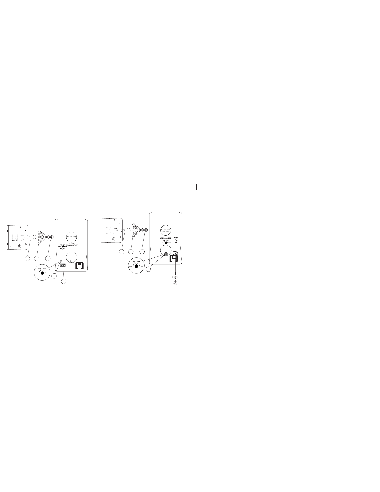
● Check if the cable length compensation selector (fig.A-4) (fig.B-4) is set to
the correct length of the system cable (0-300m/900ft max.) connecting
monitor and camera.
● Open casing and push out the slotted opening in the centre of the
case back.
● Inser t screw with washer (fig.A-1) (fig.B-1) from inside the case.
● Slide the bracket joint (fig.A-2) (fig.B-2) onto the screw, cur ved side first.
● Slide the pin through the yoke (fig.A-3) (fig.B-3) and screw the assembly
together.
Focus adjustment
The focus is preset.No further adjustment is possible.
System connection
Connect the cable to the output of the camera.
The lens
Caution: Do not touch the glass of the lens. T his could damage the
delicate coating on its surface.If the lens has to be cleaned, use a
special lens cleaning tissue, available at any good camera store.
Focus range
The built-in lens provides an optimal image sharpness for objects between
1 metre and infinity (depth of field).
GB
3
Observation Camera
Introduction
Your new CCD camera is developed for use with the Philips Observation
System Monitor,register ing images via the monitor,as well as input
contacts for connecting external alarm devices.
Installation
Warning: Disconnect the monitor from the mains supply before
disconnecting a camera or accessory.
Only operating the stand-by key is not sufficient.
When the mains supply is connected,all camera lines are scanned.The
monitor uses this to register the camera configuration of the system and
to check whether any modifications have been made.
Alarm inputs
N.B. B&W Cameras only
The camera has a three-pole terminal block for connecting alarm sensors,
such as door contacts.For normally open (N.O.) sensors, connect to
contacts N.O.(fig.A-6).For normally closed (N.C.) sensors,connect to
contacts N.C.(fig.A-6)
!
GB
2
The illustrations to which this manual refers,are shown on the front and
back jacket flap
Page 5

5
Cable
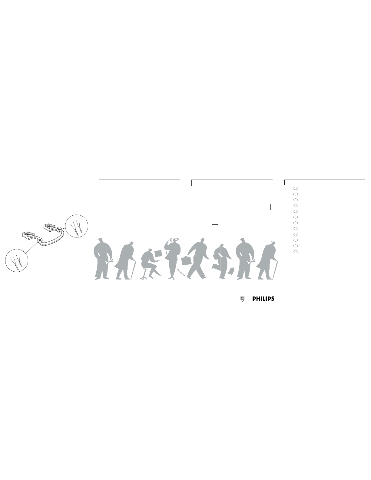
A 4-wire sytem cable (see specifications) is supplied as standard.
For optimum picture quality a standard dual ‘twisted-pair’(telephone)
cable should be used (fig.C).
The maximum distance that can be bridged (without a cable extension
adapter) between the monitor and the cameras is 300 meters (200 meters
for colour cameras).
Caution: The plugs used for the observation system have the same
dimensions as standard telephone plugs. Never connect a telephone to
the camera or system monitor.
Tips for maintenance
Cleaning - The outside of the camera can be cleaned with a moist flufffree cloth or a chamois leather cloth.
When cleaning the lens a special lens cleaning cloth should be used.
Do NOT use cleaning fluids based on alcohol,methylated spirit,
ammonia etc..
Avoid direct contact with water.
GB
4
 Loading...