

Page 1
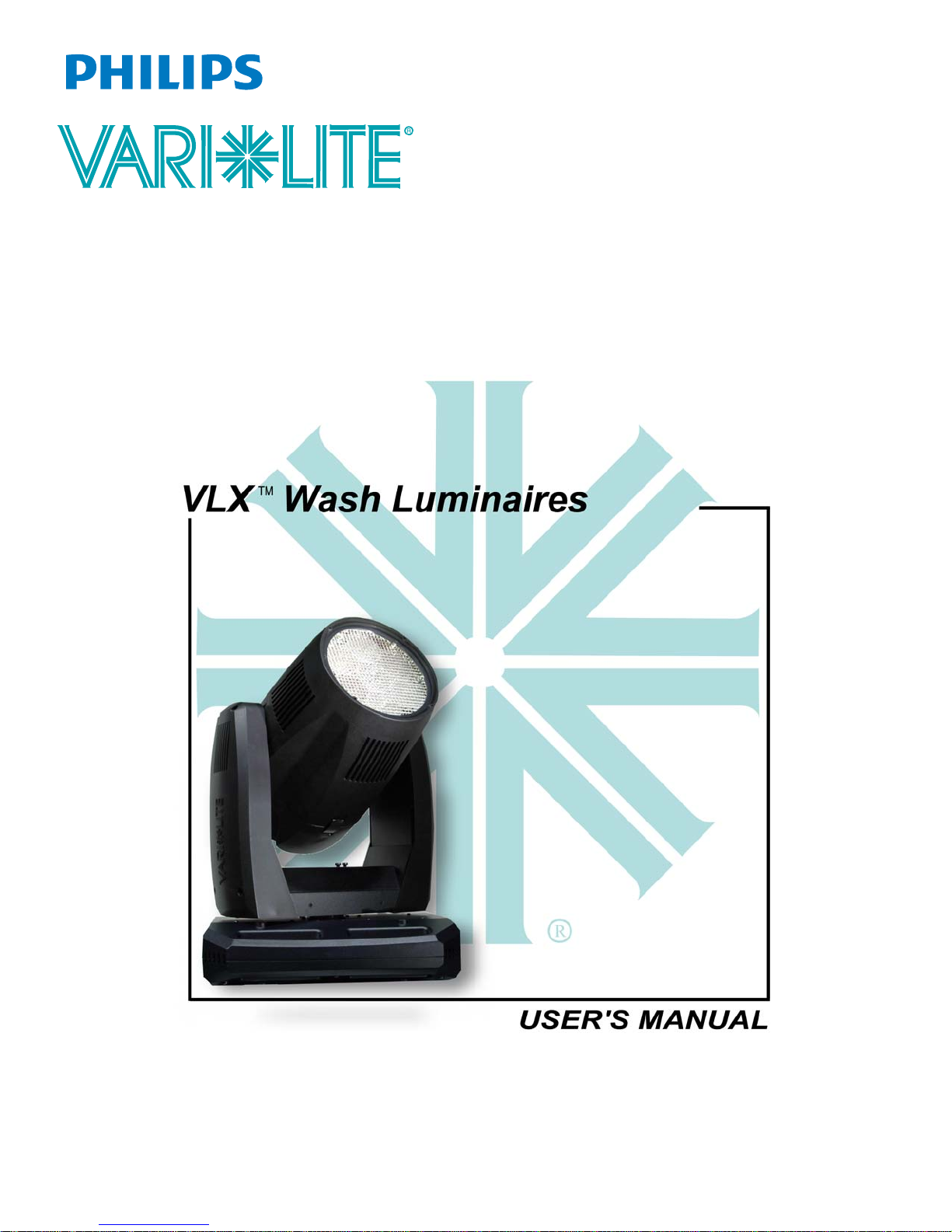
Page 2

VARI❋LITE® is a trademark owned by Genlyte Thomas Group LLC and is registered in the United States and
other countries.
VL500™ (and the individual product designations), VL1000™ (and the individual product designations),
VL2000™, VL2201™, VL2202™, VL2400™ (and the in div idu al p r od uct desi gnatio ns), VL2500™, VL3000™,
VL3500™, VLX™, Series VLX™, Series 500
DICHRO❋TUNE™, VARI❋IMAGE™, VARI❋BRITE™
™
, Series 1000™, Series 2000™, Series 3000™,
and the Vari-Lite Asterisk are also trademarks
owned by Genlyte Thomas Group LLC.
All other brand or product names which may be mentioned in this manual are trademarks or registered trademarks
of their respective companies or organizations.
VLX™ Wash Luminaire User’s Manual
The information furnished in this manual is for informational use only and is subject to change without notice.
Please check www.vari-lite.com for latest version. Vari-Lite assumes no responsibility or liability for any errors or
inaccuracies that may appear in this manual. All information and graphics are property of Vari-Li te, a Philips group
company, 10911 Petal Street Dallas, Texas 75238 USA.
Version as of: 15 April 2010
Part number: 02.9690.0001 A
VLX™ Wash Luminaire User’s Manual
©2009 - 2010 Vari-Lite, a Philips group company. All Rights Reserved.
Page 3

How To Obtain Warranty Service
A copy of the Vari-Lite Limited Warranty was included in the shipping package for this
VARI ❋LITE® product.
To obtain w arranty service, please contact customer service at 1-877-VARI-LITE (1-877-827-4548),
+1-214-647-7880, or [email protected] and request a Return Material Authorization
(RMA) for warranty service. You will need to provide the model and serial number of the item being
returned, a description of the problem or failure and the name of the registered user or organization. If
available, you should have your sales invoice to establish the date of sale as the beginning of the
warranty period.
Once you obtain the RMA, pack the unit in a secure shipping container or in its original packing box.
Be sure to clearly indicate the RMA number on all packing lists, correspondence, and shipping labels.
If available, please include a copy of your invoice (as proof of purchase) in the shipping container.
With the RMA number written legibly on or near the shipping address label, return the unit, freight
prepaid, to:
Vari-Lite
Attention: Warranty Service (RMA#___________)
10911 Petal Street
Dallas, Texas 75238 USA
FOREWORD
As stated in the warranty, it is required that the shipment be insured and FOB our service center.
02.9690.0001 A 15 April 2010 i
Page 4

VARI❋LITE® - VLX™ WASH LUMINAIRE USER’S MANUAL
Compliance Notice
FCC
This equipment has been tested and found to comply with the limits for a Class A digital device
pursuant to Part 15 of FCC Rules. These limits are designed to provide reasonable protection against
harmful interference when this equipment is operated in a commercial environment. This equipment
generates, uses, and can radiate radio frequency energy and, if not installed and used in accordance
with Vari-Lite system, service, and safety guidelines, may cause harmful interference to radio
communications. Operation of this equipment in a residential area is likely to cause harmful
interference, in which case the user will be required to correct the interference at his/her own expense.
Declaration of Conformity
We declare, under our sole responsibility, that this product complies with the relevant clauses of the
following standards and harmonized documents:
Safety
EN 60598-1:2000 Luminaire Safety Standard, General Requirements
EN 60598-2-17:1989/A2: 1991 Specification for Luminaires for Stage and Studio Lighting
EMC
EN61000-6-2: 2001, Immunity Standard for industrial environments
EN61000-6-4: 2001, Emission Standard for industrial environments
W e certify that the product conforms to the protectio n requirements of council di rectives: Low Voltage
Directive 2006/95/EC and 89/336/EEC (EMC). Equipment referred to in this declaration of
conformity was first manufactured in 2009 in compliance with these standards.
ii 15 April 2010 02.9690 .0001 A
Page 5

Safety Notice
It is extremely important to read ALL safety information and instructions provided in this manual and
any accompanying documentation before installing and operating the products described herein. Heed
all cautions and warnings during installation and use of this product.
Safety symbols used throughout this manual are as follows:
GENERAL INFORMATION PERTAINING TO PROTECTION AGAINST ELECTRICAL SHOCK,
FIRE, EXPOSURE TO EXCESSIVE UV RADIATION, AND INJURY TO PERSONS CAN BE
FOUND BELOW.
WARNING:
INSTRUCTIONS FOR CONTINUED PROTECTION AGAINST FIRE
1. VARI❋LITE® luminaires have been designed for use with specific lamp types. The VLX™
Wash Luminaire uses special LED devices. Installing another type of light sources may be
hazardous and will void your warranty.
2. Luminaires may be mounted on any type of surface as long as mounting instructions are followed.
See instructions detailed in this manual.
3. Note distance requirement from combustible materials or illuminated objects for VARI❋LITE®
luminaires.
FOREWORD
CAUTION advising of potential damage to product.
WARNING advising of potential injury or death to persons.
WARNING:
INSTRUCTIONS FOR CONTINUED PROTECTION AGAINST ELECTRICAL SHOCK
1. VARI❋LITE® luminaires are designed for dry locations only. Exposure to rain or moisture may
damage luminaire.
2. Disconnect power before servicing any VARI❋LITE® equipment.
3. Servicing to be performed by qualified personnel only.
02.9690.0001 A 15 April 2010 iii
Page 6

VARI❋LITE® - VLX™ WASH LUMINAIRE USER’S MANUAL
WARNING:
INSTRUCTIONS FOR CONTINUED PROTECTION AGAINST EXCESSIVE EXPOSURE
TO UV RADIATION
1. Many VARI❋LITE® luminaires use a lamp that produces UV radiation. DO NOT look directly at
lamp.
2. It is hazardous to operate luminaires without lens or shield. Shields, lenses, or ultraviolet screens
shall be changed if they have become visibly damaged to such an extent that their effectiveness is
impaired. For example, by cracks or deep scratches.
WARNING:
INSTRUCTIONS FOR PROTECTION AGAINST INJURY TO PERSONS
1. Exterior surfaces of the luminaire will be hot during operation. Use appropriate safety equipment
(gloves, eye protection, etc.) when handling and adjusting hot equipment and components.
2. Luminaires will have a hot lamp when operating. Disconnect power and allow lamp to cool before
replacing.
3. Arc lamps emit ultraviolet radiation which can cause serious skin burn and eye inflammation.
Additionally, arc lamps operate under high pressure at very high temperatures. Should the lamp
break, there can exist a danger of personal injury and/or fire from broken lamp particles being
discharged.
4. Wear eye protection when relamping.
5. Appropriate safety equipment (gloves, eye protection) should be used when handling damaged
lamps.
6. If lamp is touched with bare hands, clean lamp with denatured alcohol and wipe with lint-free
cloth before installing or powering up the luminaire.
7. The lamp shall be changed if it has become damaged or thermally deformed.
WARNING:
RF INTERFERENCE
1. This is a Class A product. In a domestic environment this product may cause radio interference, in
which case, the user may be required to take adequate measures.
ARC LAMP CHARACTERISTIC CONSIDERATIONS
1. Arc lamps require a period of time to relight after a power interruption or a severe voltage dip. In
some cases, lamp will automatically relight after it has cooled depending on Lamp Power-Up State
configuration setting.
2. Burning position is Universal.
iv 15 April 2010 02.9 690.0001 A
Page 7

Sicherheitshinweise
Es ist äußerst wichtig, ALLE Sicherheitsinformationen und -hinweise in diesem Handbuch und dem
beiliegenden Informationsmaterial zu lesen, bevor Sie die hierin beschriebenen Produkte installieren
bzw. bedienen. Halten Sie bei der Installation und dem Einsatz dieses Produkts alle Warnhinweise und
Vorsichtsmaßnahmen ein.
Folgende Sicherheitssymbole werden in diesem Handbuch verwendet:
VORSICHT - weist auf möglichen Produktschaden hin.
WARNUNG - weist auf mögliche Körperverletzung und Lebensbedrohung hin.
NACHSTEHEND FINDEN SIE ALLGEMEINE HINWEISE ÜBER
SICHERHEITSVORKEHRUNGEN GEGEN ELEKTROSCHOCK, FEUER, ÜBERHÖHTE UVSTRAHLUNG UND KÖRPERVERLETZUNGEN.
WARNUNG:
HINWEISE ZUM FEUERSCHUTZ
1. VARI❋LITE®-Scheinwerfer sind ausschließlich für den Einsatz mit bestimmten Lampentyps.
Achten Sie auf den Lampentyp (LED), bevor Sie die jeweiligen Lampen ersetzen. Die Installation
eines anderen Lampentyps kann gefährlich sein.
2. Scheinwerfer können auf jeder beliebigen Oberfläche montiert werden, solange Sie die
Montageanweisungen befolgen. Detaillierte Hinweise finden Sie in diesem Handbuch.
3. Beachten Sie die Einhaltung des erforderlichen Sicherheitsabstandes der VARI❋LITE®-
Scheinwerfer von brennbarem Material oder beleuchteten Objekten.
FOREWORD
WARNUNG:
HINWEISE ZUM SCHUTZ GEGEN ELEKTROSCHOCK
1. VARI❋LITE®-Scheinwerfer eignen sich ausschließlich für trockene Standorte. Regen oder
Feuchtigkeit können die Scheinwerfer beschädigen.
2. Unterbrechen Sie die Stromzufuhr, bevor Sie mit der Arbeit an VARI❋LITE®-Geräten beginnen.
3. Die Geräte sollten nur von qualifiziertem Personal gewartet werden.
02.9690.0001 A 15 April 2010 v
Page 8

VARI❋LITE® - VLX™ WASH LUMINAIRE USER’S MANUAL
WARNUNG:
HINWEISE ZUM SCHUTZ GEGEN ÜBERHÖHTE UV-STRAHLUNG
1. Viele VARI❋LITE®-Scheinwerfer verwenden die Lampentyp, der UV-Strahlen abgibt.
SCHAUEN SIE NICHT direkt in die Lampe.
2. Es ist gefährlich, Leuchten ohne Linsen oder Blenden zu bedienen. Blenden, Linse n oder
Ultraviolettschirme müssen ausgetauscht werden, sofern deren Schutzwirkung durch sichtbare
Beschädigung (z. B. Sprünge oder Schrammen) eingeschränkt ist.
WARNUNG:
HINWEISE ZUM SCHUTZ GEGEN KÖRPERVERLETZUNGEN
1. Bei Betrieb sind die Außenflächen der Scheinwerfer heiß. Verwenden Sie bei der Bedienung von
aufgeheizter Apparatur die jeweils geeignete Sicherheitsausrüstung (Handschuhe, Augenschutz
etc.).
2. Bei Betrieb der Scheinwerfer ist die Lampe heiß. Unterbrechen Sie die Stromzufuhr und lassen Sie
die Lampe abkühlen, wenn Sie diese austauschen.
3. Bogenlampen senden ultraviolette Strahlen aus, die Hautverbrennungen und Augenentzündungen
verursachen können. Der Betrieb von Bogenlampen erfolgt unter Hochdruck und bei hohen
Temperaturen. Sollte die Lampe zerbrechen, besteht die Gefahr von Körperverletzung bzw. von
Feuer, das von Lampenteilen ausgelöst werden kann.
4. Tragen Sie beim Austausch der Lampen einen Augenschutz.
5. Die geeignete Sicherheitsausrüstung (Handschuhe, Augenschutz) sollte beim Umgang mit
beschädigten Lampen verwendet werden.
6. Wenn die Lampe mit bloßen Händen berührt wird, reinigen Sie sie mit denaturiertem Alkohol und
einem flusenfreien Tuch, bevor Sie die Scheinwerfer installieren oder in Betrieb nehmen.
7. Wenn die Lampe beschädigt oder durch Hitzeeinwirkung deformiert ist, muß diese ausgetauscht
werden.
WARNUNG:
HF-INTERFERENZ
1. Es handelt sich um ein Produkt der Klasse A. In einer Wohnumgebung kann das Produkt Hochfrequenzstörungen verursachen. In diesem Fall müssen eventuell geeignete Maßnahmen getroffen
werden.
BESONDERHEITEN VON BOGENLAMPEN
1. Bogenlampen benötigen eine gewisse Zeitdauer, um nach einem Stromausfall oder einem
Spannungsgefälle wieder aufzuleuchten. In einigen Fällen wird die Lampe nach Abkühlung
automatisch wieder aufleuchten, je nach der Systemkonfigurationseinstellung des Lampeneinschaltungsstatus.
2. Die Brennposition ist Universal.
vi 15 April 2010 02.9 690.0001 A
Page 9

Notes de sécurité
Avant de procéder à l’installation des produits décrits dans ce guide et de les mettre en marche, il est
extrêmement important de lire TOUS les renseignements et TOUTES les directives de sécurité
contenues dans ce guide ainsi que toute documentation jointe. Tenir compte de tous les avertissements
et suivre toutes les précautions pendant l’installation et l’utilisation de cet appareil.
Les symboles de sécurité utilisés dans ce guide sont les suivants :
ATTENTION Ce symbole annonce que l’appareil risque d’être endommagé.
AVERTISSEMENT Ce symbole annonce qu’il y a risque d’accident grave ou même fatal.
CETTE SECTION CONTIENT DES INFORMATIONS GÉNÉRALES POUR SE PROTÉGER
CONTRE LES DÉCHARGES ÉLECTRIQUES , LES INCENDIES, L’EXPOSITION EXCESSIVE
AUX RAYONS UV ET TOUT AUTRE ACCIDENT POUVANT ENTRAÎNER DES BLESSURES.
FOREWORD
AVERTISSEMENT:
DIRECTIVES POUR SE PROTÉGER CONTRE LES INCENDIES
1. Les luminaires VARI❋LITE® ont été conçus pour être utilisés uniquement avec certaines type de
lampes. Vérifier le type de lampe (LED) avant de remplacer les lampes. L’installation d’un autre
type de lampe peut poser un danger.
2. Les luminaires peuvent être fixés sur tout type de surface tant que les directives de montage sont
respectées. Voir les explications détaillées dans ce guide.
3. Vérifier la distance à respecter entre les matériaux combustibles ou les objets illuminés et les
luminaires VARI❋LITE®.
AVERTISSEMENT:
DIRECTIVES POUR SE PROTÉGER CONTRE LES DÉCHARGES ÉLECTRIQUES
1. Les luminaires VARI❋LITE® sont conçus pour une utilisation au sec uniquement. Une
exposition à la pluie et à l’humidité risque d’endommager le luminaire.
2. Débrancher l’appareil avant de procéder à la révision de tout matériel VARI❋LITE®.
3. Les révisions doivent être effectuées uniquement par des personnes qualifiées.
02.9690.0001 A 15 April 2010 vii
Page 10

VARI❋LITE® - VLX™ WASH LUMINAIRE USER’S MANUAL
AVERTISSEMENT:
DIRECTIVES POUR SE PROTÉGER CONTRE UNE EXPOSITION EXCESSIVE AUX
RAYONS UV
1. Plusieurs luminaires VARI❋LITE® utilisent une lampe qui produit des rayons UV. NE PAS fixer
son regard sur la lampe.
2. L’utilisation des luminaires sans lentille ou blindage pose des risques. Tous blindages, lentilles ou
écrans ultraviolet visiblement endommagés au point que leur efficacité en est affectée doivent être
remplacés, par exemple s’il y a des fissures ou de profondes rayures.
AVERTISSEMENT:
DIRECTIVES POUR SE PROTÉGER CONTRE LES ACCIDENTS POUVANT ENTRAÎNER
DES BLESSURES
1. Les surfaces externes du luminaire deviennent brûlantes quand l’appareil est en marche. Pour
manœuvrer ou ajuster des appareils brûlants et leurs composants, se protéger suffisamment (gants,
protection pour les yeux, etc.).
2. La lampe du luminaire est brûlante lorqu’il est en marche. Débrancher le courant et attendre que la
lampe ait refroidi avant de la remplacer.
3. Les lampes à arc émettent des rayons ultraviolets pouvant causer de graves brûlures sur la peau et
une inflammation des yeux. De plus, les lampes à arc fonctionnent sous haute tension à de très
hautes températures. Si la lampe se casse, les particules de la lampe cassée peuvent causer
blessures et/ou incendie en s’éparpillant.
4. Se protéger les yeux pour remplacer la lampe.
5. Utiliser des appareils de protection appropriés (gants, protection des yeux) pour manier des lampes
endommagées.
6. Si la lampe a été touchée avec des mains nues, la nettoyer avec de l’alcool dénaturé et l’essuyer
avec un chiffon non-pelucheux avant d’installer ou de brancher le luminaire.
7. Si la lampe a été endommagée ou a reçu une déformation thermique, elle doit être remplacée.
AVERTISSEMENT:
INTERFÉRENCE RF
1. Cet appareil est de Classe A. Dans un environnement domestique, cet appareil peut causer des
interférences radio, et si c’est le cas, l’utilisateur peut avoir à prendre des mesures adéquates.
CONSIDÉRATIONS DES CARACTÉRISTIQUES DE LAMPES À ARC
1. Après une interruption de courant ou une baisse importante de voltage, les lampes à arc mettent du
temps avant de se rallumer. Dans certains cas, la lampe se rallumera automatiquemet après s’être
refroidie. Cela dépend de la manière dont le système est réglé pour le statut de mise en marche de
la lampe.
2. La position Brûler est Universelle.
viii 15 April 2010 02.9690 .0001 A
Page 11

Aviso sobre Seguridad
Es muy importante leer TODA la in formación e instrucciones sobre seguridad que se indica en este
manual así como en los documentos adjuntos antes de instalar y operar los productos descritos. Se
debe prestar atención a todos los avisos y advertencias durante la instalación y uso de este producto.
Los símbolos de seguridad usados en este manual son los siguientes:
CUIDADO, indica posibles daños al producto.
ADVERTENCIA, indica posibles lesiones o muerte a las personas.
LA INFORMACIÓN GENERAL RELACIONADA A LA PROTECCIÓN CONTRAGOLPES DE
CORRIENTE ELÉCTRICA, INCENDIO, EXPOSICIÓN EXCESIVA A RADIACIÓN ULTRA
VIOLETA Y LESIONES A LAS PERSONAS SE PUEDE ENCONTRAR SEGUIDAMENTE:
ADVERTENCIA:
INSTRUCCIONES PARA PROTECCIÓN CONTINUA CONTRA INCENDIO
1. Las luminarias VARI❋LITE® han sido diseñadas para ser usadas solamente con algunas
lámparas. T ome nota del tipo de lámpara (LED) antes de reemplazarla. Instalación de otro tipo de
lámpara puede ser peligroso.
2. Las luminarias se pueden instalar en cualquier tipo de superficie siempre que se sigan las
instrucciones de instalación. Vea las instrucciones detalladas en este manual.
3. Tome nota de los requerimientos de distancia de materiales combustibles u objetos iluminados
para las luminarias VARI❋LITE®.
FOREWORD
ADVERTENCIA:
INSTRUCCIONES PARA PROTECCIÓN CONTINUA CONTRA CHOQUE ELÉCTRICO
1. Las luminarias VARI❋LITE® están diseñadas solamente para lugares secos. La exposición a la
lluvia o humedad pueden dañar la luminaria.
2. Desconecte la energía antes de dar servicio a cualquier equipo de VARI❋LITE®.
3. El servicio debe ser realizado solamente por personal calificado .
02.9690.0001 A 15 April 2010 ix
Page 12

VARI❋LITE® - VLX™ WASH LUMINAIRE USER’S MANUAL
ADVERTENCIA:
INSTRUCCIONES PARA PROTECCIÓN CONTINUA CONTRA LA EXPOSICIÓN
EXCESIVA DE RADIACIÓN ULTRA VIOLETA
1. Muchas luminarias VARI❋LITE® usan un tipo de lámpara que produce radiación UV. NO mire
directamente a la lámpara.
2. Es peligroso operar luminarias sin lentes o protectores. Debe cambiar los protectores, lentes o
pantallas ultravioletas si se aprecia que han sido dañadas, y que su efectividad pudiera estar
deteriorada. Por ejemplo, si tuvieran rajaduras o raspaduras profundas.
ADVERTENCIA:
INSTRUCCIONES PARA PROTECCIÓN CONTRA LESIONES DE PERSONAS
1. Las superficies exteriores de las luminarias están calientes durante su operación. Use un equipo de
seguridad apropiado (guantes, protección para los ojos, etc.) cuando haga ajustes en el equipo y
componentes que están calientes.
2. Cuando las luminarias están en operación la lámpara estará muy caliente. Desconecte la energía y
deje que la lámpara se enfríe antes de reemplazarla.
3. Las lámparas de arco emiten radiaciones ultravioletas que pueden ocasionar serias quemaduras a la
piel e inflamación a los ojos. Además, las lámparas de arco operan a alta presión y muy alta
temperatura. Si la lámpara se rompe, puede existir el peligro de lesiones al personal o un incendio
ocasionado por las partículas de la lámpara rota que se caen.
4. Use protección para los ojos cuando vuelve a colocar una lámpara nueva.
5. Use un equipo de seguridad apropiado (guantes, protección para los ojos, etc.) cuando trabaje con
lámparas dañadas.
6. Si toca la lámpara con las manos, limpie la lámpara con alcohol desnaturalizado y con tela sin
pelusas antes de instalar o volver a conectar la luminaria.
7. Cambie la lámpara si está dañada o deformada termicamente.
ADVERTENCIA:
INTERFERENCIA RF
1. Este es un producto de Clase A. En el ambiente de la casa este producto puede ocasionar
radiointerferencia, en cuyo caso, el usuario debe tomar las medidas adecuadas.
CONSIDERACIONES SOBRE LAS CARACTERÍSTICAS DE LA LÁMPARA DE ARCO
1. Las lámparas de arco requieren un período de tiempo para volver a iluminarse después de una
interrupción de energía o de una severa caída de voltaje. En algunos casos, la lámpara se volverá a
iluminar en forma automática después que se ha enfriado dependiendo de la configuración del
sistema de energía de la lámpara.
2. La posición de encendido es universal.
x 15 April 2010 02.9690 .0001 A
Page 13

FOREWORD
02.9690.0001 A 15 April 2010 xi
Page 14
VARI❋LITE® - VLX™ WASH LUMINAIRE USER’S MANUAL
xii 15 April 2010 02.9690 .0001 A
Page 15

Table of Contents
Introduction
About This Manual ...................................................... ............................................................. 1
Additional Documentation........................................................................................................ 1
Text Conventions .................................................................................................. .... ................ 2
Customer Service...................................................................................................................... 2
Chapter 1. Description
Features
Standard Features.............................................................. ........................................................ 4
Components
Included Items.................................................................................................. ..... .... ................ 5
Replacement Items/Accessories................................................................................................ 5
Luminaire Overview............................................................................... ..... .... ......................... 6
TABLE OF CONTENTS
Chapter 2. Installation
Power and Data Cabling Requirements
AC Power................................................................................................................................ 10
Current vs. Voltage............................................................................................................ 11
Data Cables........................................................................... ..... ............................................. 12
Recommended Cable Types/Manufacturers...................................................................... 13
Male Termination Connector ............................................................................................ 13
Installation Procedures
Hanging the Luminaire ........................................................................................................... 14
Floor Mounting the Luminaire................................................................................................ 17
Connecting Data and Power.................................................................................................... 17
Powering Up
Power Up and Configuration Procedure........................................................................ ..... .... 18
Addressing
Program Starting Address....................................................................................................... 19
Chapter 3. Operation
DMX Operation
Channel Mapping.................................................................................................................... 22
Control Channel Functions..................................................................................................... 24
VLX Operational Modes (from Control Channel Settings):............................................. 25
DMX Mapping
Color & Intensity Control....................................................................................................... 26
Color Mixing..................................................................................................................... 26
Color Time Control ........................................................................................................... 27
LED Intensity Control....................................................................................................... 27
02.9690.0001 A 15 April 2010 xiii
Page 16

VARI❋LITE® - VLX™ WASH LUMINAIRE USER’S MANUAL
Intensity Time Control ...................................................................................................... 28
Beam Control..................................................................................................................... 28
Strobe................................................................................................................................. 28
Beam Spreader................................................................................................................... 28
Beam Time ........................................................................................................................ 29
Luminaire Movement.............................................................................................................. 30
Luminaire Pan ................................................................................................................... 30
Luminaire Tilt...................................................................... .... .......................................... 30
Focus Time........................................................................................................................ 30
Luminaire Timing
Timing Channel Information............................... .................................................................... 31
Updating Software
USB Download and Programming ......................................................................................... 40
Transferring Software From Luminaire to Luminaire ............................................................ 41
Chapter 4. Menu System
Menu Operation
What Is the Menu System? ..................................................................................................... 44
Controls Operation.................................................................................................................. 44
Default State...................................................................................................................... 46
Menu Functions
Menu System Overview.......................................................................................................... 47
Menu System Function Chart ............................................................. .... ................................ 48
Menu Function Definitions..................................................................................................... 51
Appendix A. Troubleshooting and Maintenance
Troubleshooting
Error Messages........................................................................................................................ 56
Troubleshooting Guide............................................................................................................ 58
Routine Maintenance
Introduction............................................................................................................................. 60
Special Cleaning and Care Instructions.................................................................................. 60
Front Lens Removal and Cleaning.......................................................................................... 61
Beam Spreader Removal for Fixed Beam Applications......................................................... 65
Cooling System Heatsink Cleaning Procedure....................................................................... 69
Appendix B. Technical Specifications
VLX™ Wash Luminaire....................................................................................... .... .............. 73
xiv 15 April 2010 02.9690 .0001 A
Page 17
Introduction
About This Manual
This manual provides necessary information regarding safety, installation, operation and routine
maintenance for the VARI❋LITE® VLX™ Wash Luminaire. Familiarizing yourself with this
information will help you to get the most out of your luminaire.
WARNING: It is important to read ALL accompanying safety and installation instructions to avoid
damage to the product and potential injury to yourself or others.
This manual covers the following models:
VLX™ Wash Luminaire 20.9690.0001 Seven x 120W RGBW LEDs
VLX™ Wash Luminaire, White 20.9690.0001.02 Seven x 120W RGBW LEDs
INTRODUCTION : ABOUT THIS MANUAL
Model Part Number Source
Additional Documentation
A service manual, for Authorized VARI❋LITE® Service Centers and technicians, of the VLX™
Wash Luminaire is available in electronic (PDF) format:
• VLX™ Wash Luminaire Service Manual (02.9690.0010)
- Testing, Troubleshooting, Component Replacement and Illustrated Parts Breakdown.
Note: Performing maintenance procedures may void the product warranty. Refer to the Vari-Lite
Limited Warranty card included in the product shipping package for more information.
Note: The VLX™ Wash Luminaire requires very little routine maintenance, but has special cleaning
instructions unlike other fixtures. Please refer to “Special Cleaning and Care Instructions” on page 60
for complete cleaning and handling requirements.
For more information regarding DMX512 systems, refer to the following document available from
United States Institute for Theatre Technology, Inc. (USITT):
• Digital Data Transmission Standard for Dimmers & Controllers plus AMX 192 Analog Multiplex
Data Transmission Standard for Dimmers & Controllers. (A copy of Recommended Practice for
DMX512 is included.)
USITT Inc.
6443 Ridings Road
Syracuse, New York 132 06-1111 USA
Tel: (800) 938-7488 Fax: (866) 398-7488 / www.usitt.org
02.9690.0001 A 15 April 2010 1
Page 18
VARI❋LITE® - VLX™ WASH LUMINAIRE USER’S MANUAL
Text Conventions
The following styles and meanings are used throughout this manual:
Style Meaning
[Button] Front panel button. Example: Press [Enter] or [ESC]
(Escape).
[Up] / [Down] / [Left] / [Right]
Arrows
MENU LCD Menu Display read-out. Example: Press [Up] / [Down]
Press either [Up] or [Down] or [Left] or [Right] arrow
button at Menu Display.
/ [Left] / [Right] arrows until LAMP appears.
Customer Service
Our Goal
At Vari-Lite, we are committed to providing you the highest quality in customer service. Our
comprehensive resources are available to help your business succeed and ensure you get the full
benefit of being a Vari-Lite customer. Whether your needs are telephone troubleshooting assistance,
product training or technical service, our full-time staff of experienced professionals are on-hand to
provide support.
How to Reach Us
For assistance in your area, call the dealer from which your product was purchased. or Contact an
Authorized VARI❋LITE® Service Center or Contact the Vari-Lite Customer Service Department,
9am - 6pm CST Monday through Friday, at the following:
phone: 1-877-VARI-LITE (1-877-827-4548) or +1-214-647-7880
email: [email protected]
Additional Resources
For additional resources and documentation, please visit our website at www.vari-lite.com and follow
the Support link.
2 15 April 2010 02.9690 .0001 A
Page 19

CHAPTER 1.
Description
This chapter contains descriptions of luminaire features and components, along with a list of
accessories that are available.
• Features
• Components
02.9690.0001 A 15 April 2010 3
Page 20

VARI❋LITE® - VLX™ WASH LUMINAIRE USER’S MANUAL
Features
Standard Features
All VLX™ Wash Luminaires have the following standard feature s:
• Seven, 120-watt replaceable custom RGBW chipsets. Each chip set contains high density red,
green, blue, and white LED emitters.
• Manufacturer rated life (LED chip sets), in excess of 10,000 hours (at full RGBW).
• Light output of approximately 14,000 lumens (white light).
• Patented optical zoom system with continuous variable field angle from approximately 23
• Zoom module is easily removable for a fixed field angle of 22
o
.
o
to 58
• High-speed strobe with multi user-selectable effects.
• Smooth pan and tilt operation through time-controlled continuous motion by way of a pair of
three-phase stepper motor systems.
•540
o
Pan and 270o Tilt with 0.3o resolution.
Note: Detailed specification are available on the Vari-Lite web site at www.vari-lite.com and in
“Technical Specifications” on page 73 in this manual.
o
.
4 15 April 2010 02.9690 .0001 A
Page 21
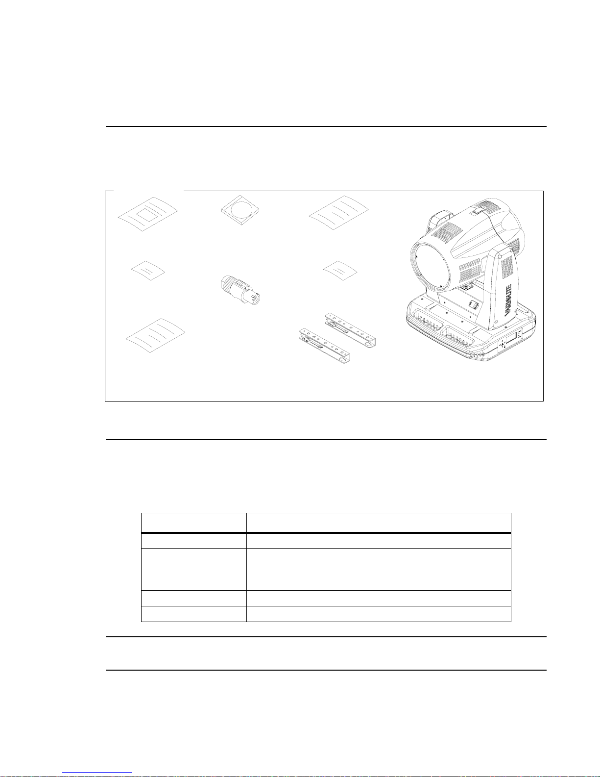
Components
Included Items
The following illustration shows all items included with the luminaire:
Included Items
Unpack & Quick
Start Sheet
Warranty Card Product Registration Card
TM
Wash Luminaire
VLX
CD ROM (User’s Manual)
Neutrik PowerCon®
AC Input Connector*
DESCRIPTION : COMPONENTS
1
Vari-Lite Customer Service
Product Support Sheet
Vari-Lite QA Certificate
*Unit supplied with AC input connector only. Users will need
to supply and build an AC input cable using this connector.
Mounting Brackets
TM
VLX
Wash Luminaire
Figure 1-1: VLX™ Wash Luminaire Packing List
Replacement Items/Accessories
The following optional and/or replacement items can be ordered directly from your Authorized
VARI ❋LITE® Dealer. (Please order by Vari-Lite part number.)
Vari-Lite P/N Accessory
22.9620.0194 Safety Cable Assembly
23.9623.0177 XLR DMX Terminator
28.8500.0054 USB Luminaire Programming Kit (Includes USB Upload Cable,
Programming Kit CD ROM, Carry Bag, and Instructions)*
55.6840.0001 Truss Hook, Mega-Clamp, Round and Square
55.6841.0001 Truss Hook, Mega-Claw for 2” Round Tube
Note: * For more information on the USB Luminaire Programming Kit, please see “USB Download
and Programming” on page 40.
02.9690.0001 A 15 April 2010 5
Page 22
VARI❋LITE® - VLX™ WASH LUMINAIRE USER’S MANUAL
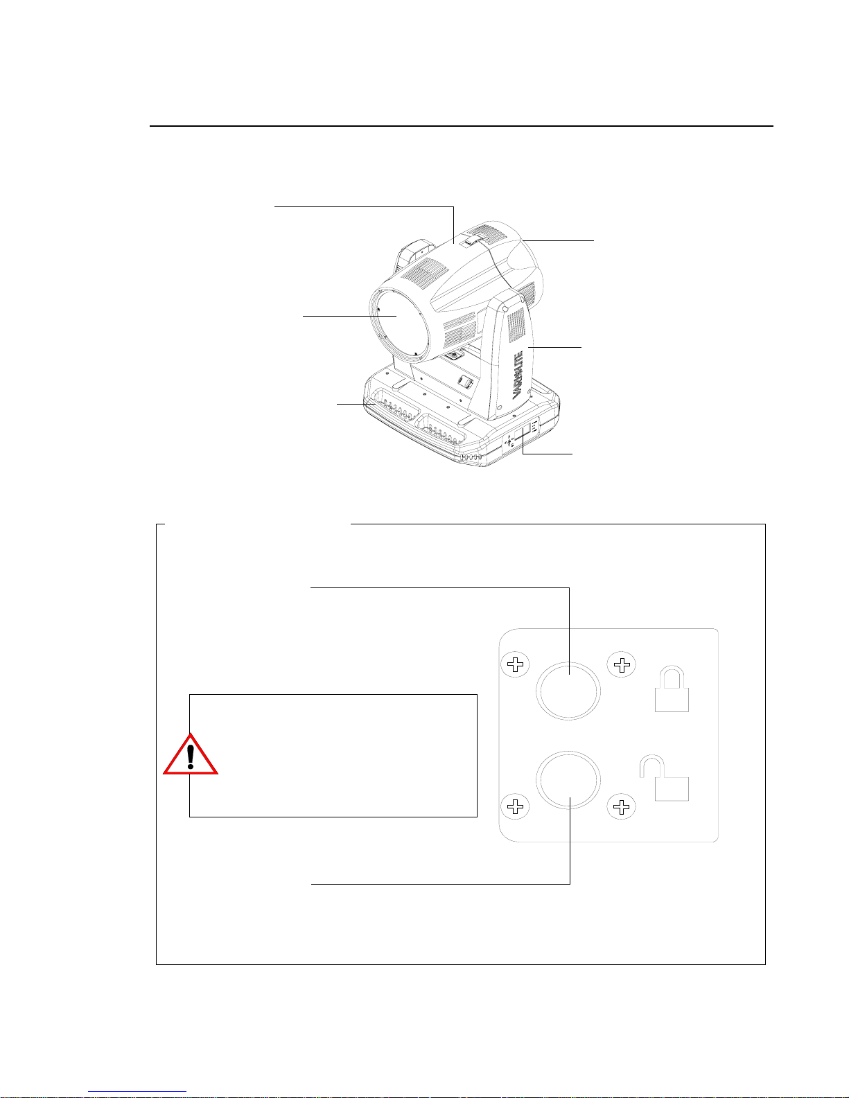
Luminaire Overview
The following illustration shows the external luminaire components and controls.
Head Assembly
Houses light source
lens and LED PCB
assemblies.
Front Lens Assembly
Upper Enclosure Assembly
Houses LED power supply
connections and menu display.
Pan & Tilt Lock Operation
Backcap Assembly
Provides access to light
source and LED cooling
assemblies.
Yoke Assembly
Houses Master Control
Board (MCB) and power
supply.
Menu Display
Used to input manual commands,
program, test, set defaults, and
access internal status information.
(See detail below)
Lock Engage
To lock pan or tilt (restricts movement).
The VLX™ Wash Luminaire has
separate Pan and Tilt locks. When the
luminaire is in use, both the Pan and Tilt
locks must be disengaged to allow free
movement of the luminaire head and
yoke assemblies.
Lock Disengage
To unlock pan or tilt (allows free movement).
Figure 1-2: VLX™ Wash Luminaire External Components and Controls
6 15 April 2010 02.9690 .0001 A
Page 23
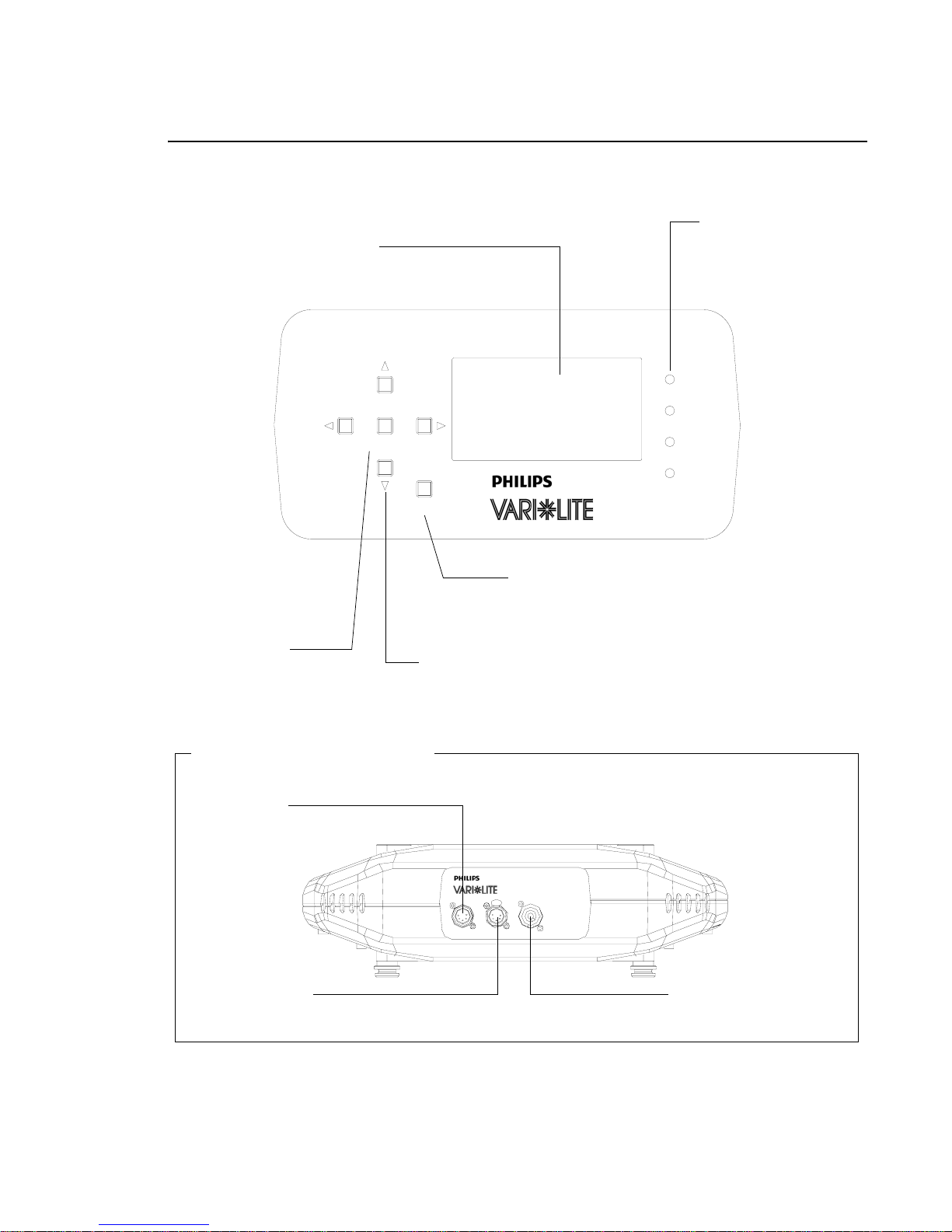
Luminaire Overview (continued)
Upper Enclosure Menu
LCD Display
Displays all Data and Luminaire Settings
DESCRIPTION : COMPONENTS
1
Status LEDs
Power State, Data
Transmit, Data
Receive, Data Error
POWER
TX
ENTER
Enter Button
To Select or Change a
Setting or Data Value
Upper Enclosure Connections
DMX Input
Connection to DMX Controls
RX
ERROR
ESC
Escape (ESC)
To Exit or Go to Previous Menu Item
Arrow Keys (Left/Right/Up/Down)
To Menu Navigate Menu Options and make Data
Selections
DMX Through
Passes DMX to Other Luminaires
Figure 1-3: VLX™ Wash Luminaire External Components and Controls
02.9690.0001 A 15 April 2010 7
AC Power Input
100 - 240VAC 50/60Hz
Page 24

VARI❋LITE® - VLX™ WASH LUMINAIRE USER’S MANUAL
Notes
8 15 April 2010 02.9690 .0001 A
Page 25

CHAPTER 2.
Installation
This chapter contains instructions for installation of the luminaire. It includes connectin g power
and data, along with instructions for powering up the luminaire for the first time and addressing
it within your system.
• Power and Data Cabling Requirements
• Installation Procedures
• Powering Up
• Addressing
WARNING: DO NOT connect or disconnect energized power cable at fixture (under load). Turn
off circuit breaker (or completely de-energize circuit) before connecting or disconnecting power
cable at fixture. Power is only removed from the fixture by disconnecting power cable from
source or turning off source circuit breaker.
02.9690.0001 A 15 April 2010 9
Page 26
VARI❋LITE® - VLX™ WASH LUMINAIRE USER’S MANUAL
Power and Data Cabling Requirements
AC Power
WARNING: DO NOT connect to three-phase Delta service in countries with 240 volt power.
WARNING: DO NOT connect or disconnect energized power cable at fixture (under load). Turn off
circuit breaker (or completely de-energize circuit) before connecting or disconnecting power cable at
fixture. Power is only removed from the fixture by disconnecting power cable from source or turning
off source circuit breaker.
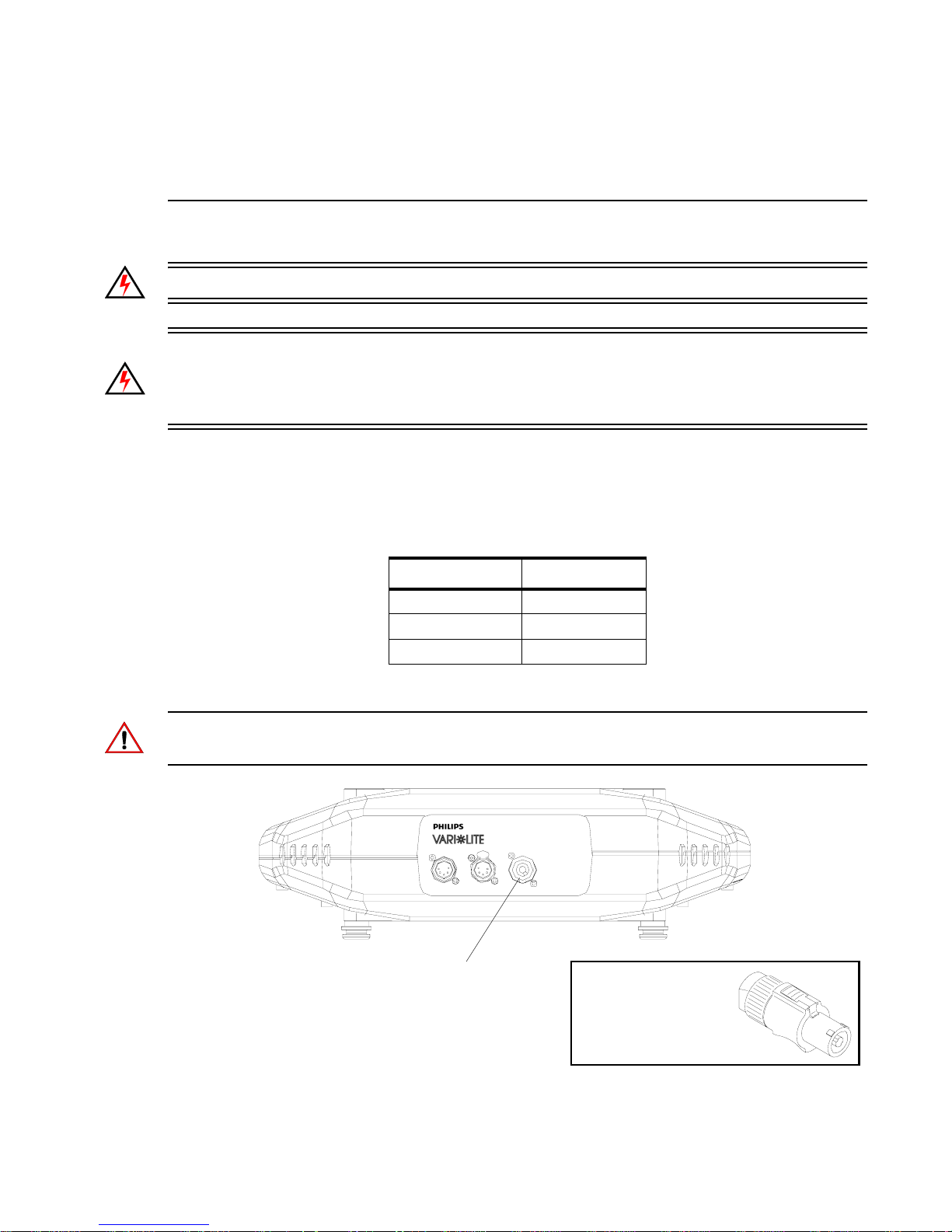
The luminaire requires standard AC power distribution from 100-240 VAC, 50/60 Hz in order to
power all internal electronics and motors. It is equipped with a 3-pole Neutrik® PowerCon® locking
connector (with contacts for line, neutral, and premating safety grounds) for the purpose of AC input.
Wire* Connection
Green/Yellow AC Ground
Blue AC Neutral
Brown AC Line
*International (Harmonized) Standard
Note: The mating Neutrik PowerCon® connector is supplied, however, you will need to purchase or
construct a cable appropriate for your application.
3-Pole Neutrik PowerCon Locking
Connector for AC Input Power
Neutrik PowerCon
Connector (supplied)
10 15 April 2010 02.9 690.0001 A
Figure 2-1: Power Connector
Page 27

INSTALLATION : POWER AND DATA CABLING REQUIREMENTS
Current vs. Voltage
The following tables provide the luminaire’s current draw at specific voltages.
Table 2-1: VLX Wash Luminaire - Current vs. Voltage*
Voltage (VAC) @ 60Hz Current (A)
100 9.0
110 8.2
120 7.5
130 6.9
140 6.4
150 6.0
160 5.6
170 5.3
180 5.0
190 4.7
200 4.5
210 4.3
220 4.1
230 3.9
240 3.8
2
*Currents given are worst case with all motors sequencing.
02.9690.0001 A 15 April 2010 11
Page 28
VARI❋LITE® - VLX™ WASH LUMINAIRE USER’S MANUAL
Data Cables
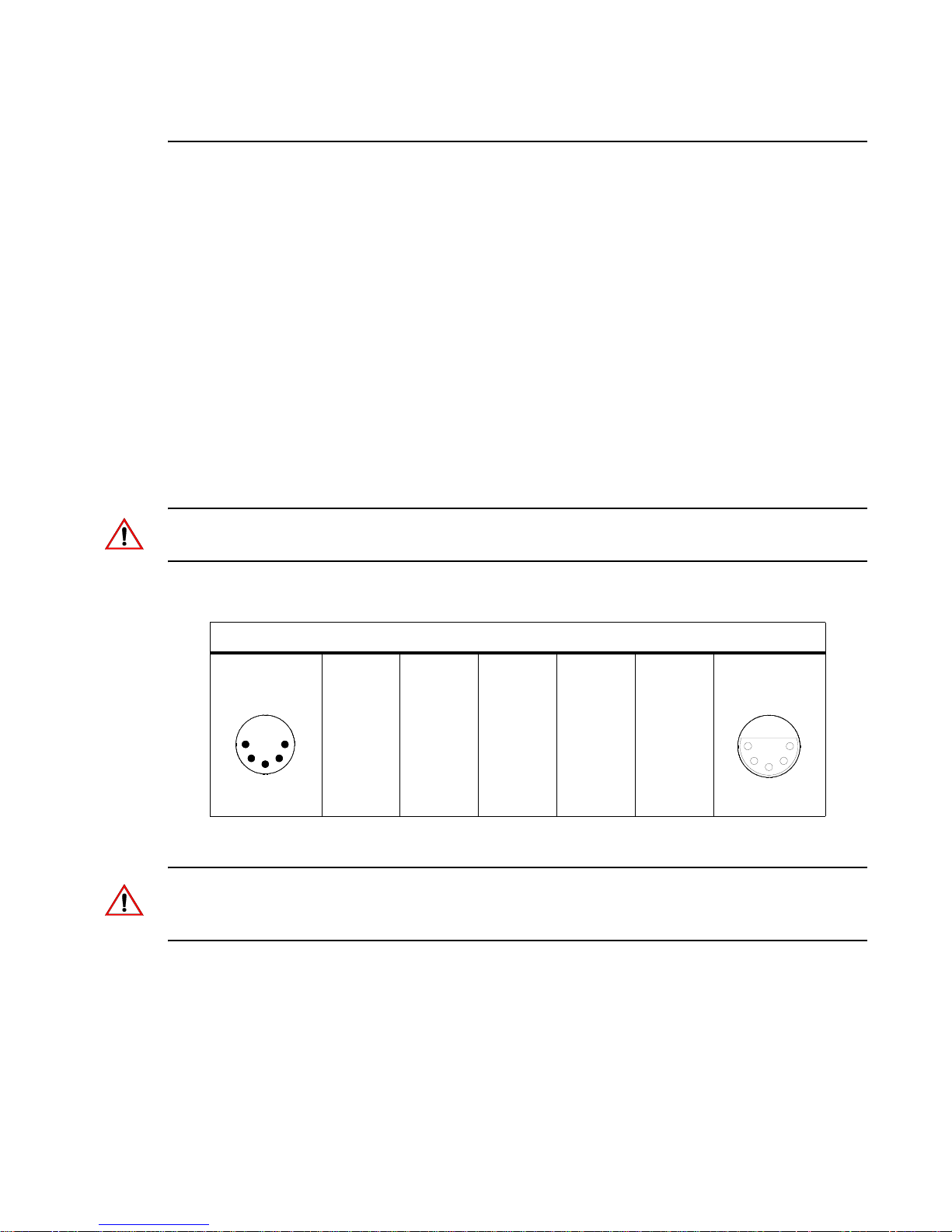
The VLX™ Wash Luminaire is equipped with two, 5-pin XLR connectors for DATA IN and DATA
THRU (out) applications. DATA IN requires a 5-pin, female XLR connector and DATA THRU
requires a 5-pin, male XLR connector. When purchasing or constructing data cables, it is important
that not only the correct cable type be used, but also quality cable to ensure a reliable DMX512 system.
Your cabling should meet the following USITT DMX specification requirements:
• Suitable for use with EIA485 (RS485) operation at 250k baud.
• Characteristic impedance 85-150 ohms, nominally 120 ohms.
• Low capacitance.
• Two twisted pairs.
• Foil and braid shielded.
• 24 AWG minimum gauge for runs up to 1000 feet (300m).
• 22 AWG minimum gauge for runs up to 1640 feet (500m).
Note: Microphone type cables and other general purpose, two-core audio or signal cables are not
suitable for use with DMX512.
The XLR 5-pin connectors should be wired as follows:
Pin/Wire Code to XLR Connectors
Data Thru
Cable Pinout
1
2
Male Conn
4
3
Pin 1
Foil &
Braided
Shield
5
Pin 2
1st
conductor
of 1st
twisted
pair
Data (-)
Pin 3
2nd
conductor
of 1st
twisted
pair
Data (+)
Pin 4
1st
conductor
of 2nd
twisted
pair
Data (-)
Pin 5
2nd
conductor
of 2nd
twisted
pair
Data (+)
Data In
Cable Pinout
5
4
Female Conn
2
3
1
Note: Refer to the USITT Recommended Practice for DMX512 guide for additional information
regarding DMX512 systems. How to obtain a copy is detailed in “Additional Documentation” on
page 1.
12 15 April 2010 02.9 690.0001 A
Page 29
INSTALLATION : POWER AND DATA CABLING REQUIREMENTS
2
Recommended Cable Types/Manufacturers
These are only a few of the suitable cable types. Any quality EIA485, twisted pair, 120 ohm, shielded
cable will also work.
Table 2-2: Recommended Cable Types
Type Pairs
1215A 2 150 PVC 26 IBM Type 6 Office cable 75
1269A 2 100 PTFE 22 (Solid) High Temp, Plenum cable 200
8102 2 100 PVC 24 UL2919 80
8132 2 120 PVC 28 UL2919 80
8162 2 100 PVC 24 UL2493 60
82729 2 100 PTFE 24 High Temp, Plenum cable 200
88102 2 100 PTFE 24 High Temp, Plenum cable 200
89696 2 100 PTFE 22 High Temp, Plenum cable 200
89729 2 100 PTFE 24 High Temp, Plenum cable 200
89855 2 100 PTFE 22 High Temp, Plenum cable 200
9729 2 100 PVC 24 UL2493 60
9804 2 100 PVC 28 UL2960 60
9829 2 100 PVC 24 UL2919 80
9842 2 120 PVC 24 UL2919 80
PC224P 2 110 Polyure-
PC224T 2 110 PVC 22 UL2464 105
PC226T 3 110 PVC 22 UL2464
ZΩ
∗
Jacket AWG Use Temp (F)
Belden Cables
Proplex Cables
22 Heavy Duty and Portable 105
thane
* Characteristic Impedance
Male Termination Connector
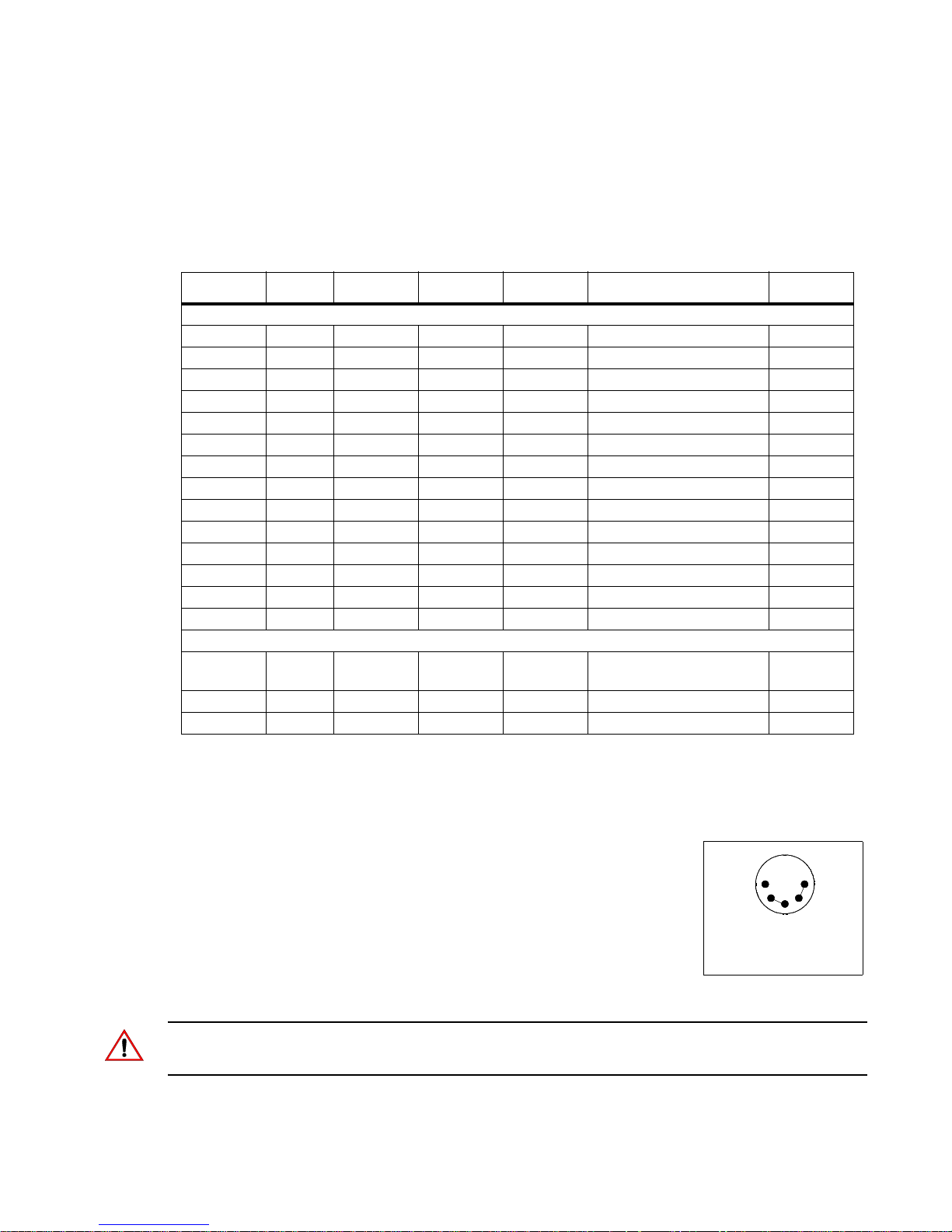
A male XLR termination connector is required at the last luminaire (or
“far end of the line”) to prevent signal reflections. Signal reflections may
cancel out the signal at certain line lengths, resulting in errors. The
terminator is also necessary for software downloads and running tests on
multiple luminaires.
To construct your own connector, you will need the
following components:
• 5-pin, male XLR connector.
• Two 1/4W 5% 120 ohm resistors.
Note: A male termination connector is also available as an accessory from Vari-Lite. See
“Replacement Items/Accessories” on page 5.
02.9690.0001 A 15 April 2010 13
1
2
Solder resistors across
pins 2 & 3, and 4 & 5
5
4
3
Page 30
VARI❋LITE® - VLX™ WASH LUMINAIRE USER’S MANUAL
Installation Procedures
Hanging the Luminaire
The VLX™ Wash Luminaire can be hung horizontally or vertically from any structure designed to
work with the type of load created by this moving luminaire. Two mounting bracket assemblies
(provided) are used to attach truss hooks or other mounting hardware as required. Many compatible
truss hooks are available from different manufacturers for your particular needs.
A minimum of one hook per truss hook bracket is required. If mounting method does not use truss
hooks, two attachment points per truss hook bracket are required. When attaching more than one point
on a single bracket, the attach points must be spaced as far apart as possible using the supplied
mounting holes.
Install mounting hardware and brackets:
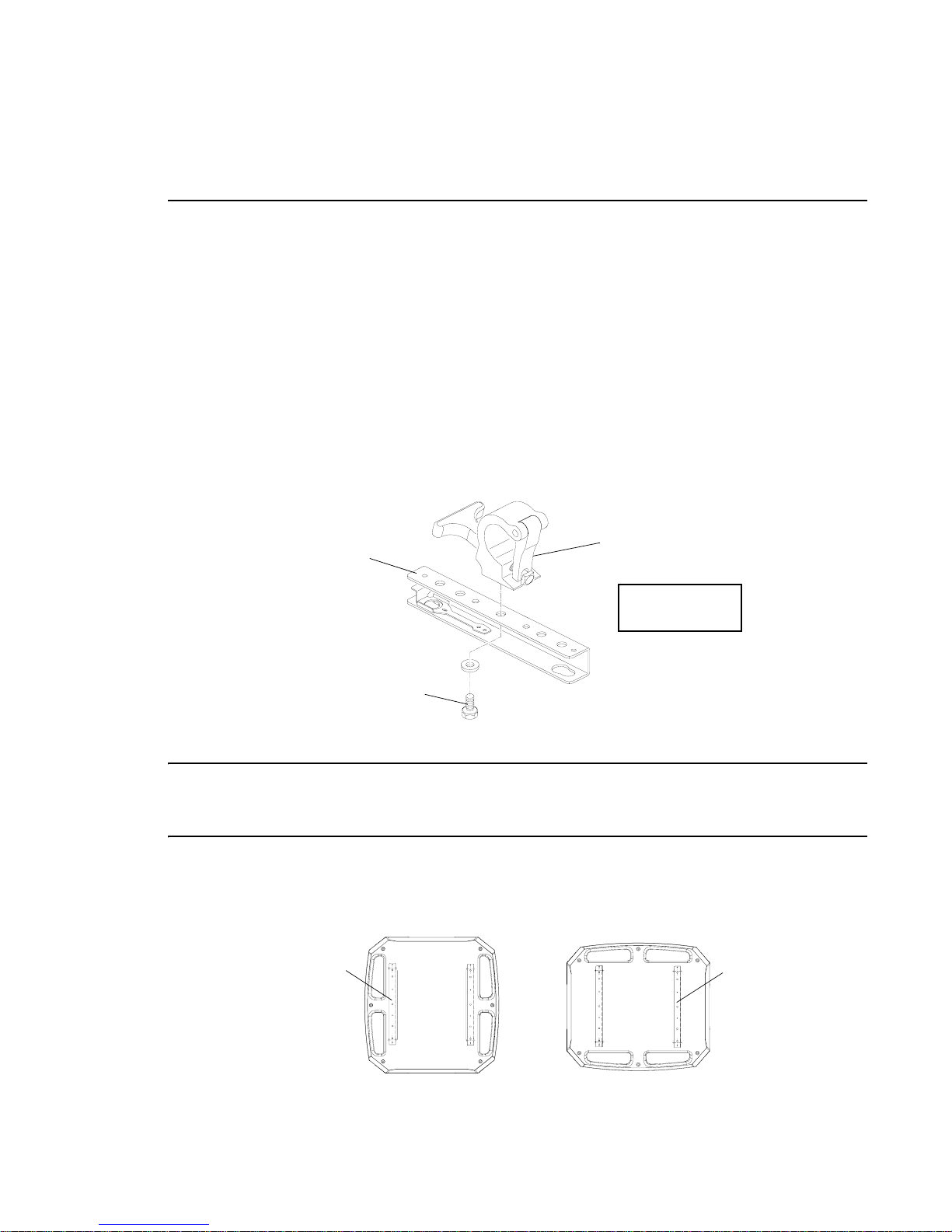
Step 1. Install truss hooks on two provided truss hook brackets as required.
Bracket
Mega Claw Truss Hook
(not provided)
Example Truss
Hook Installation
Truss Hook Hardware
(not provided)
Figure 2-2: Installing Truss Hooks
Note: Various types of truss hooks can be used. The Mega Claw truss hook (as shown in the example
above) as well as many other standard hooks, can be ordered separately. See “Replacement Items/
Accessories” on page 5.
Step 2. Determine required configuration of bracket installation. Brackets may be installed in either
orientation as shown in Figure 2-3, but both must face the same direction. Figure 2-4 shows
bracket installation details.
Bracket
Bracket
14 15 April 2010 02.9 690.0001 A
Figure 2-3: Bracket Orientation Options
Page 31
INSTALLATION : INSTALLATION PROCEDURES
2
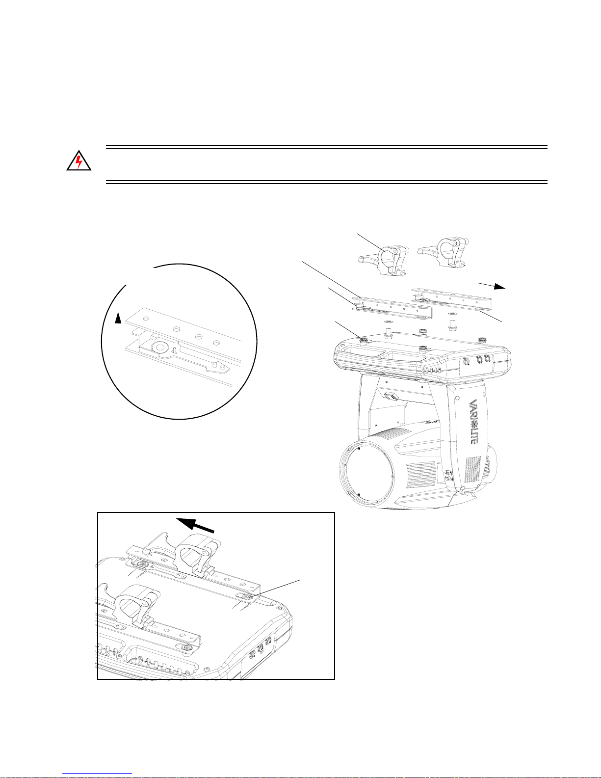
Step 3. While pulling up on locking mechanism release, fit keyed holes onto raised mounting
buttons at bottom of enclosure. Slide forward and release locking mechanism to lock in
place. Ensure brackets are locked securely. (Always face brackets in same direction as
shown.)
WARNING: Ensure that the bracket locking mechanism is fully seated after the bracket is installed
on the luminaire.
Example Truss Hook
(not included)
Locking
Mechanism
Press up to
install or release
Mounting
Bracket
Locking
Mechanism
Raised Mounting
Buttons (4 each)
Face brackets in
same direction for
all configurations
Keyed
Hole
Figure 2-4: Installing Brackets on Luminaire Enclosure
02.9690.0001 A 15 April 2010 15
Fit over buttons and
slide forward to lock
Locked
Page 32
VARI❋LITE® - VLX™ WASH LUMINAIRE USER’S MANUAL
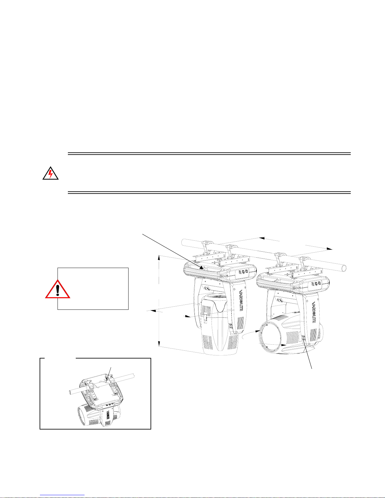
Installing in Truss:
Step 1. Using two people, lift luminaire into mounting position.
Step 2. Secure in place with truss hook. Ensure truss hook hardware that locks hook in place (e.g.
wing bolt) is properly tightened and that luminaire is fully supported.
Step 3. Attach safety cable (as required) as follows:
a. Connect one end of cable to luminaire handle.
b. Loop at least once around truss/pipe and attach other end of cable to other handle.
Step 4. Connect power and data cables according to procedure given in “Connecting Data and
Power” on page 17.
WARNING: DO NOT connect or disconnect energized power cable at fixture (under load). Turn off
circuit breaker (or completely de-energize circuit) before connecting or disconnecting power cable at
fixture. Power is only removed from the fixture by disconnecting power cable from source or turning
off source circuit breaker.
Step 5. Be sure pan and tilt locks are disengaged (refer to “Luminaire Overview” on page 6 for
details) to allow full head and yoke movement.
Use enclosure handles for safety cable anchor
points (refer to Top View illustration below).
22.0 in
559.0 mm
(on centers)
Top View
Safety Cable:
Recommended for all
hanging installations
and may be required
by local codes.
Safety Cable (not included)
Figure 2-5: Hanging Configuration and Dimensions
27.4 in
696.0 mm
17.5 in
445.0 mm
21.5 in
546.0 mm
Head Tilt Lock
16 15 April 2010 02.9 690.0001 A
Page 33
INSTALLATION : INSTALLATION PROCEDURES
2
Floor Mounting the Luminaire
The luminaire enclosure is sufficient to stabilize the luminaire in a floor installation,
provided that the mounting surface is flat and sturdy. Also, the area around the
luminaire must be free of debris and moisture.
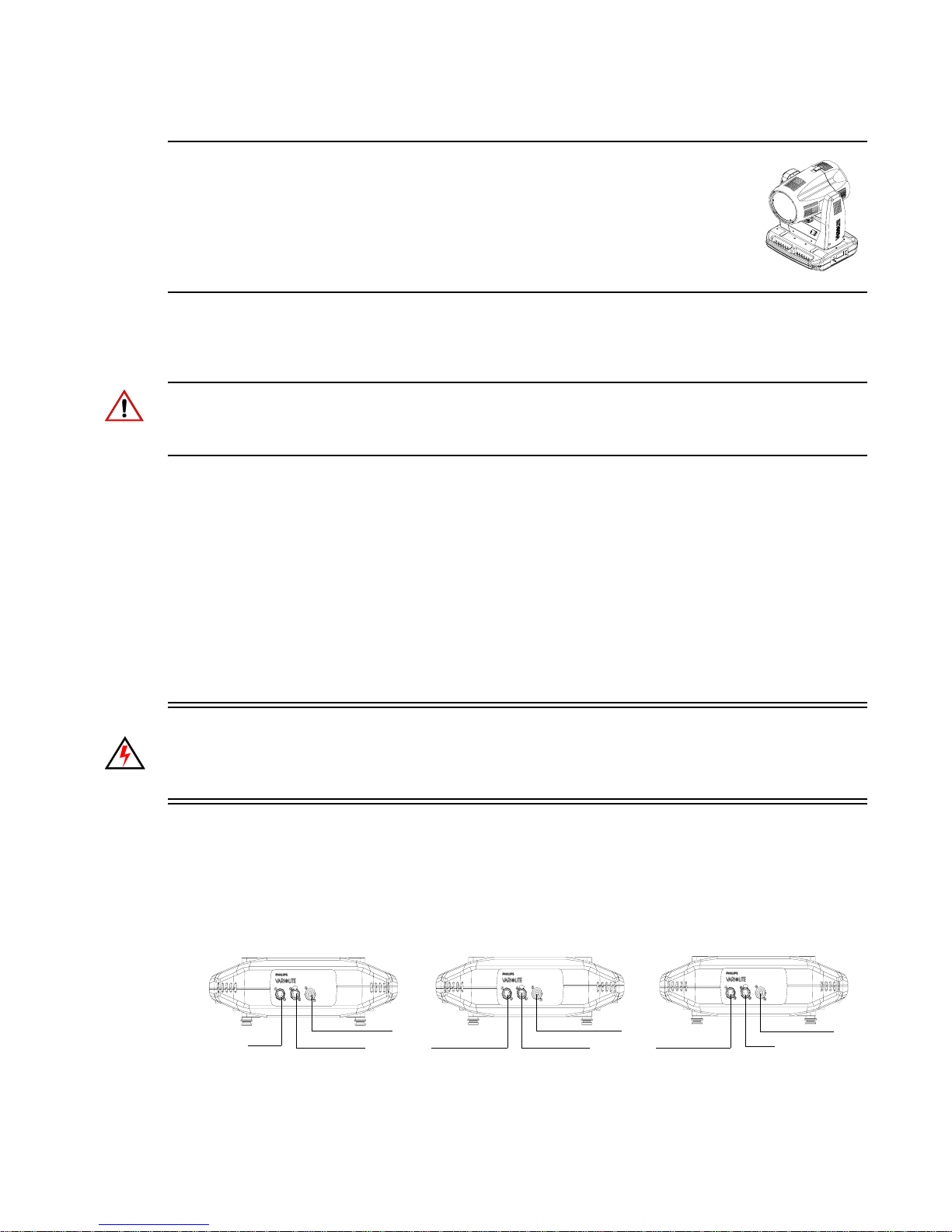
Connecting Data and Power
A maximum of 32 luminaires may be connected in any one DMX data link.
Note: This maximum limit applies to the luminaire "daisy chain" only. Your system or console may
require fewer luminaires on a single data link path. Consult your console documentation for more
information.
To connect power and data:
Step 1. Connect data cable from console to first luminaire in chain at DATA IN connector.
Step 2. If required, connect additional data cables from DATA THRU connectors to DATA IN
connectors of remaining luminaires in link.
Step 3. At last luminaire in link, install male termination connector at DATA THRU connector.
(Luminaires and other devices on the same DMX chain may not function properly without
termination.)
Step 4. Connect AC input cable connector to fixture before connecting to power input source or
energizing power cable.
WARNING: DO NOT connect or disconnect energized power cable at fixture (under load). Turn off
circuit breaker (or completely de-energize circuit) before connecting or disconnecting power cable at
fixture. Power is only removed from the fixture by disconnecting power cable from source or turning
off source circuit breaker.
Step 5. Dress AC input and data cables and secure them so they do not interfere with luminaire head
and yoke movement.
Step 6. Be sure pan and tilt locks are disengaged (refer to “Luminaire Overview” on page 6 for
details) to allow full head and yoke movement.
Data In
(from console)
02.9690.0001 A 15 April 2010 17
AC
Data Thru
Data Thru
Figure 2-6: Connecting Power and Data
AC
Termination
AC
Connector
Page 34
VARI❋LITE® - VLX™ WASH LUMINAIRE USER’S MANUAL
Powering Up
Power Up and Configuration Procedure
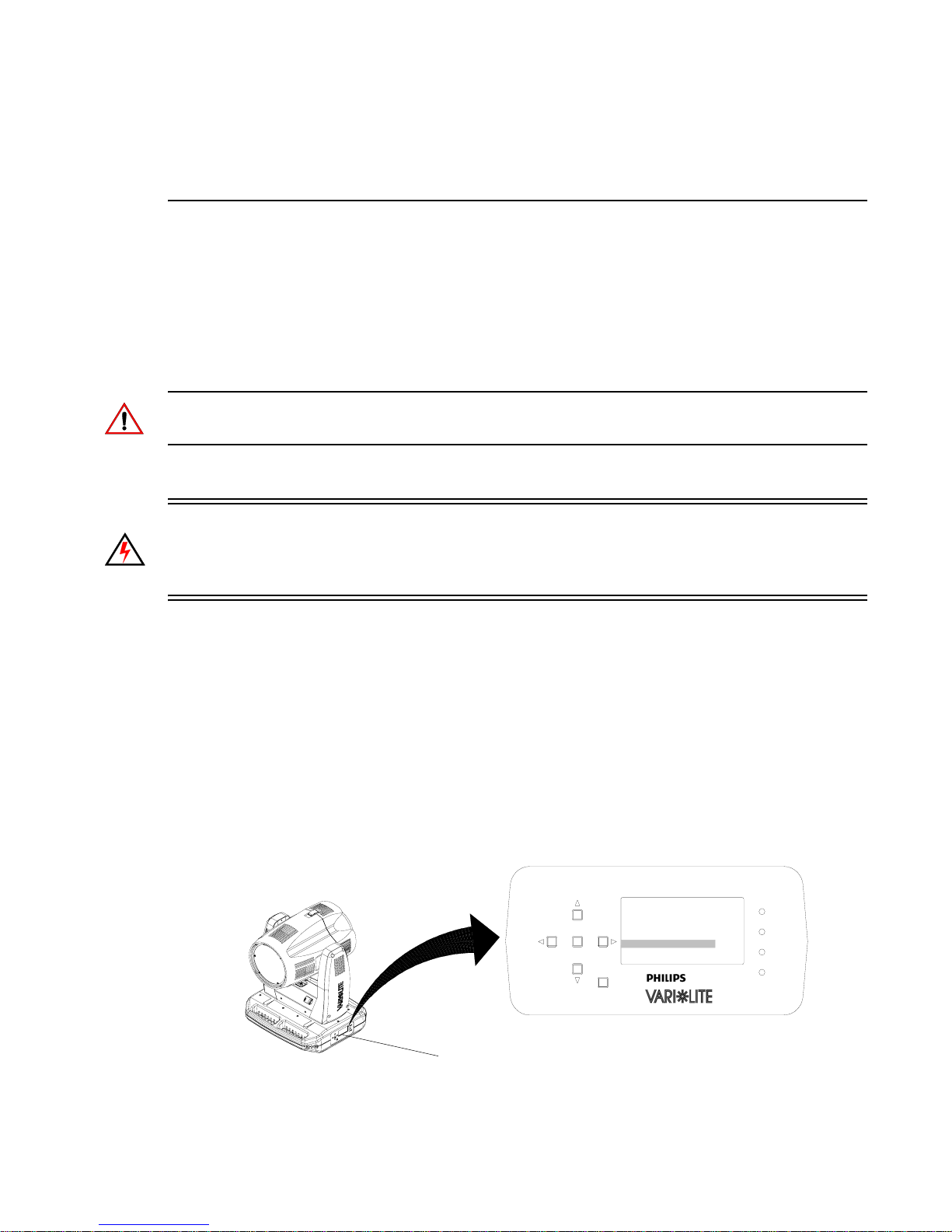
When AC power is initially applied, the luminaire immediately begins a calibration sequence that steps
it through pan and tilt movements. The beam mechanism also moves through a full range of motion.
After calibration, the luminaire head either stops at its “home” position (which positions the pan axis at
mid-rotation and the head parallel to the yoke with the lens pointing away from the luminaire upper
enclosure) or it moves to its current DMX-defined position when DMX data is present. All internal
mechanisms also move to their “home” or DMX-defined positions.
CAUTION: Before applying power, be sure the luminaire is hung or positioned so that the head and
yoke can move freely without restriction.
To power up:
WARNING: DO NOT connect or disconnect energized power cable at fixture (under load). Turn off
circuit breaker (or completely de-energize circuit) before connecting or disconnecting power cable at
fixture. Power is only removed from the fixture by disconnecting power cable from source or turning
off source circuit breaker.
Step 1. At each luminaire, connect power cable to fixture.
Step 2. Be sure pan and tilt locks are disengaged (refer to “Luminaire Overview” on page 6 for
details) to allow full head and yoke movement.
Step 3. Energize each connected circ uit.
Step 4. Luminaire will automatically cycle through calibration and stop at "home" position.
LCD Display - Luminaire Calibration Status
During luminaire calibration or re-calibration, the progress of the operation is displayed on the
luminaire’s LCD Display. Information includes description of process and a progress bar.
VLX Wash Menu LCD Display
Calibrating
Pan / Zoom
ENTER
ESC
VLX Wash Menu
POWER
TX
RX
ERROR
Figure 2-7: VLX Wash LCD Display - Luminaire Calibration Status
18 15 April 2010 02.9 690.0001 A
Page 35

Addressing
Program Star ting Address
The address setting for DMX console controlled systems is entered using the Menu Display (refer to
“Menu Operation” on page 44). The luminaire retains the DMX address even when power is removed.
Note: Refer to your console operating instructions for specific information regarding its addressing
requirements.
Program a DMX starting address:
Step 1. Press [ESC] to access the main menu of the luminaire.
Step 2. Press [Up] / [Down] arrows until Address appears. Press [Enter].
Step 3. Press [Up] / [Down] arrows to enter starting address.
Step 4. Press [Enter] to set.
INSTALLATION : ADDRESSING
2
02.9690.0001 A 15 April 2010 19
Page 36

VARI❋LITE® - VLX™ WASH LUMINAIRE USER’S MANUAL
Notes
20 15 April 2010 02.9 690.0001 A
Page 37

CHAPTER 3.
Operation
This chapter contains instructions for operating the luminaire using DMX control and for
updating the internal software. For Menu options and detailed information, see “Menu
Operation” on page 44.
• DMX Operation
• DMX Mapping
• Luminaire Timing
• Updating Software
02.9690.0001 A 15 April 2010 21
Page 38
VARI❋LITE® - VLX™ WASH LUMINAIRE USER’S MANUAL
DMX Operation
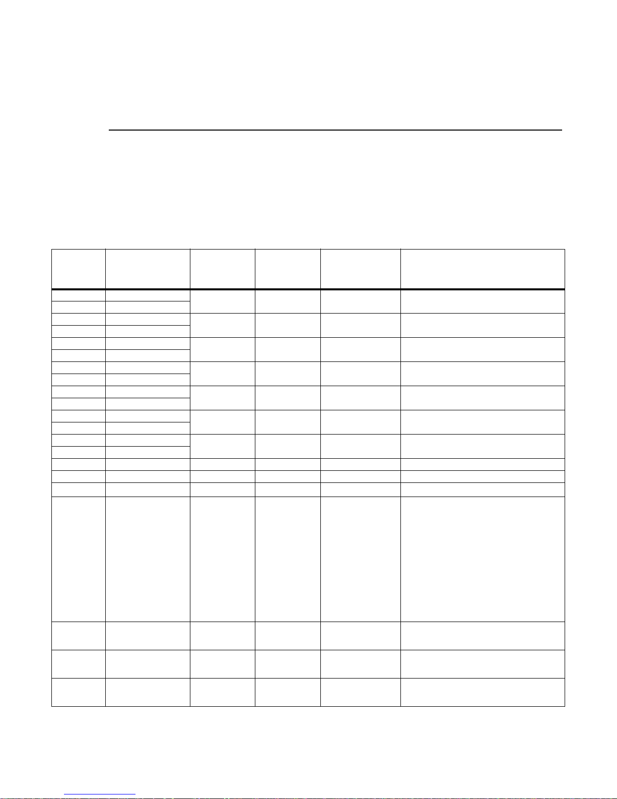
Channel Mapping
These tables assume a DMX start address of 1. When a different starting address is used, this address
becomes channel 1 function and other functio ns follow in sequence.
Table 3-1: VLX™ Wash Luminaire Mapping Mode 1
DMX
Channel
1 Intensity - High
2 Intensity - Low
3 Pan - High Byte
4 Pan - Low Byte
5 Tilt - High Byte
6 Tilt - Low Byte
7 Red - High Byte
8 Red - Low Byte
9 Green - High Byte
10 Green - Low Byte
11 Blue - High Byte
12 Blue - Low Byte
13 White - High Byte
14 White - Low Byte
15 Unused N/A N/A N/A For Future Use
16 Unused N/A N/A N/A For Future Use
17 Beam Spreader 0 - 255 0 - 100% 0
18 Strobe 0 - 255 0 - 100% 0
19 Intensity Time 0 - 255 0 - 100% 255
20 Focus Time 0 - 255 0 - 100% 255
21 Color Time 0 - 255 0 - 100% 255
Parameter Range DMX Range%
0 - 65535 0 - 100% 0 16-bit control for Intensity of LED settings.
0 - 65535 0 - 100% 32768
0 - 65535 0 - 100% 32768
0 - 65535 0 - 100% 0 16-bit control of Red LEDs from 0 to full.
0 - 65535 0 - 100% 0 16-bit control of Green LEDs from 0 to full.
0 - 65535 0 - 100% 0 16-bit control of Blue LEDs from 0 to full.
0 - 65535 0 - 100% 0 16-bit control of White LEDs from 0 to full.
Default - These
values are recom-
mended console
default values
Description
16-bit control of Pan - 540
16-bit control of Tilt - 270
Controls beam angle from 23
Controls strobe operations as follows:
Open = DMX 0 - 2
Closed = DMX 3 - 5
Slow Rand = DMX 6 - 7
Med Rand = DMX 8 - 10
Fast Rand = DMX 11 - 12
Strobe Range = DMX 13 - 127 (fastest)
Pulse + Slow Rand = DMX 128 - 129
Pulse + Med Rand = DMX 130 - 131
Pulse + Fast Rand = DMX 132 - 133
Pulse + Range = DMX 134 - 191
Pulse - Slow Rand = DMX 192 - 193
Pulse - Med Rand = DMX 194 - 195
Pulse - Fast Rand = DMX 196 - 197
Pulse - Range = DMX 198 - 255
Allows for luminaire timing of intensity. Profile
should default to DMX 255 for smoothest console fade times.
Allows for luminaire timing of pan and tilt. Profile
should default to DMX 255 for smoothest console fade times.
Allows for luminaire timing of color mixing. Profile
should default to DMX 255 for smoothest console fade times.
o
of movement.
o
of movement.
o
to 58o (DMX 255)
VLX™ Wash Luminaire mapping continued on the next page.
22 15 April 2010 02.9 690.0001 A
Page 39

OPERATION : DMX OPERATION
Table 3-1: VLX™ Wash Luminaire Mapping Mode 1
3
22 Beam Time 0 - 255 0 - 100% 255
23 Control 0 - 255 0 - 100%
Allows for luminaire timing of zoom. Profile
should default to DMX 255 for smoothest console fade times.
Used to set different modes, parameters, and
functions of the VLX Wash. Set control channel
value for desired action. Hold value for at least 3
seconds. Set control channel value to 0 without
any scaling.
Default Setting on Console = DMX 0
Reset All to Defaults** = DMX 5 - 7
Quiet Mode† = DMX 11 - 13
Level Light Mode† = DMX 14 -16
Constant Fans Mode† = DMX 17 - 19
Normal Mode† = DMX 20 - 22
Dimmer Curve LINEAR† = DMX 31 - 32
Dimmer Curve SQUARE LAW† = DMX 34 - 35
Full Luminaire Reset = DMX 81 - 87
Color Calibration OFF† = DMX 116 - 117
Color Calibration ON† = DMX 118 - 120
Fixture Sleep = DMX 245 - 249
Fixture Wake Up* = DMX 250 - 255
Notes
:
*Please note that Fixture Wake Up will completely re-calibrate the fixture.
** When resetting to defaults, the following will
be enabled on the luminaire:
• Normal Mode
• Dimmer Curve SQUARE LAW
• Color Calibration ON
† These settings require the Command Lock in
Menu to be set to OFF in order to change on
Control Channel. Resetting to defaults will turn
Command Lock OFF.
02.9690.0001 A 15 April 2010 23
Page 40
VARI❋LITE® - VLX™ WASH LUMINAIRE USER’S MANUAL
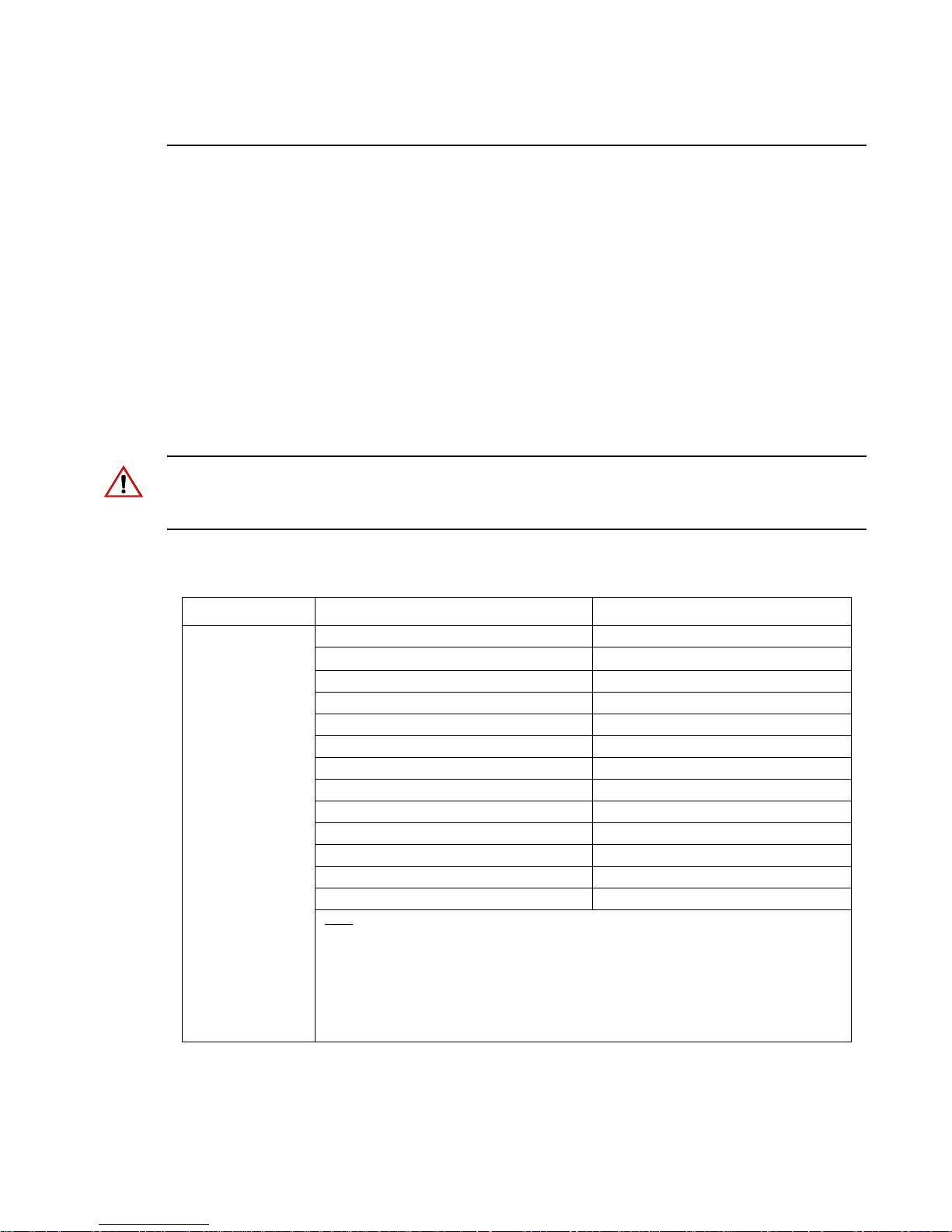
Control Channel Functions
Used to set different modes, parameters, and functions of the VLX™ Wash Luminaire via the control
console. Set control channel value for desired action. Hold value for at least 3 seconds.
Set control channel value to 0 without any scaling. Discrete values must be used; not manual controls
such as faders or encoders (see chart below for values).
To use control channel functions:
Step 1. Select an action to be sent.
Step 2. Set control channel value for desired action (for example, 84 for reset). Hold value for at
least 3 seconds.
Step 3. Set control channel value to zero. (This must occur without any scaling values. Action will
be voided if other values are detected between action value and zero.)
Note: A numerical keypad is required for sending values. An encoder or fader does not allow for a
quick value change, which is required to effect the control functions. However, the encoders on some
consoles include discreet value capability.
Table 3-2: Control Channel Functions
DMX Channel Control Channel Function Control Channel DMX Value
Default Setting on Console 0
5 - 7
23
Reset All to Defaults**
Quiet Mode† 11 - 13
Level Light Mode† 14 - 16
Constant Fans Mode
Normal Mode
Dimmer Curve LINEAR† 31 - 32
Dimmer Curve SQUARE LAW
Full Luminaire Reset 81 - 87
Color Calibration OFF
Color Calibration ON
Fixture Sleep 245 - 249
Fixture Wake Up* 250 - 255
Notes:
*Please note that Fixture Wake Up will completely re-calibrate the fixture.
** When resetting to defaults, the following will be enabled on the luminaire:
• Normal Mode
• Dimmer Curve SQUARE LAW
• Color Calibration ON
† These settings require the Command Lock in Menu to be set to OFF in order to change on Control Channel. Resetting to defaults will turn Command Lock OFF.
† 17 - 19
† 20 - 22
† 34 - 35
† 116 - 117
† 1 18 - 120
24 15 April 2010 02.9 690.0001 A
Page 41

OPERATION : DMX OPERATION
3
VLX Operational Modes (from Control Channel Settings):
Quiet Mode
Quite Mode lowers LED output levels for low noise operation. In Quiet Mode, LED junction
temperatures are lowered and fan noise set to minimum. Fans will still vary in speed, but will not
exceed the set (lower noise) limit.
Level Light Mode
Level Light Mode maintains a reduced LED output to keep various fixtures from operating at different
levels depending upon thermal situations. The fans will run full speed, regardless of junction
temperatures.
Constant Fans Mode
Constant Fans Mode sets fans to maximum speed and will keep them operating at full, regardless of
LED junction temperatures.
Normal Mode (default setting)
Normal Mode operates the luminaire’s fans according to the LED's junction temperature. Fans will
vary in speed according to thermal readings by MCB.
02.9690.0001 A 15 April 2010 25
Page 42
VARI❋LITE® - VLX™ WASH LUMINAIRE USER’S MANUAL
DMX Mapping
Color & Intensity Control
The luminaire’s color system is composed of a color mixing seven 120-watt RGBW LEDs. The
following sections describe these components .
Color Mixing
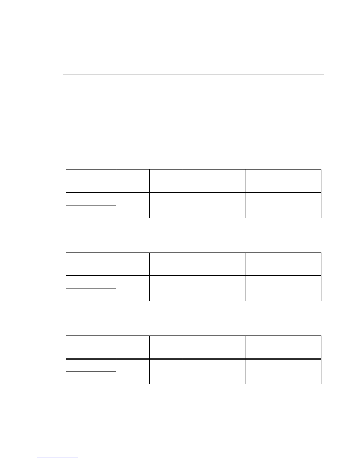
All color mixing is accomplished via the luminaire’s seven 120-watt RGBW LEDs using 16-bit
control.
Table 3-3: DMX Map for Color Mixing - Red LEDs
DMX Channel % Value
7 (High Byte)
8 (Low Byte)
.
DMX Channel % Value
9 (High Byte)
10 (Low Byte)
.
DMX Channel % Value
DMX
Value
0 - 100 0 - 65535 0
Default - These values
are recommended
console default values
16-Bit Control of Red LEDs
Table 3-4: DMX Map for Color Mixing - Green LEDs
DMX
Value
0 - 100 0 - 65535 0
Default - These values
are recommended
console default values
16-Bit Control of Green LEDs
Table 3-5: DMX Map for Color Mixing - Blue LEDs
DMX
Value
Default - These values
are recommended
console default values
Action
from 0 to Full
Action
from 0 to Full
Action
11 (High Byte)
12 (Low Byte)
26 15 April 2010 02.9 690.0001 A
0 - 100 0 - 65535 0
16-Bit Control of Blue LEDs
from 0 to Full
Page 43

OPERATION : DMX MAPPING
3
.
Table 3-6: DMX Map for Color Mixing - White LEDs
DMX Channel % Value
13 (High Byte)
0 - 100 0 - 65535 0
14 (Low Byte)
DMX
Value
Color Time Control
Table 3-7: DMX Map for Color Time Control
DMX Channel % Value
21 0 - 100 0 - 255 255
DMX
Value
LED Intensity Control
Provides 16-bit control of LED intensity settings.
Default - These values
are recommended
console default values
Default - These values
are recommended
console default values
Action
16-Bit Control of White LEDs
from 0 to Full
Action
Allows for luminaire timing of
color mixing. Profile should
default to DMX 255 for
smoothest console fade
times.
DMX Channel % Value
1 (High Byte)
0 - 100 0 - 65535 0
2 (Low Byte)
Table 3-8: DMX Map for LED Intensity
DMX
Value
Default - These values
are recommended
console default values
Action
16-bit control for Intensity of
LED settings
02.9690.0001 A 15 April 2010 27
Page 44
VARI❋LITE® - VLX™ WASH LUMINAIRE USER’S MANUAL
Intensity Time Control
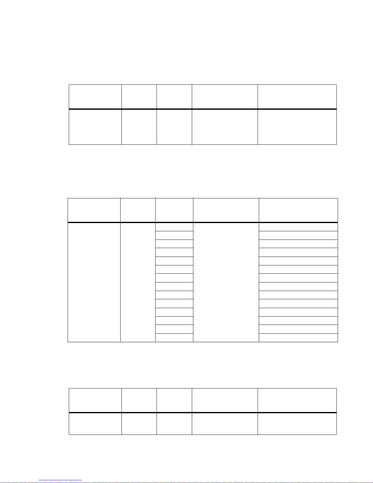
Table 3-9: DMX Map for Intensity Time Control
DMX Channel % Value
19 0 - 100 0 - 255 255
Beam Control
Strobe
Table 3-10: DMX Map for Strobe
DMX Channel % Value DMX Va lue
18 0 - 100
DMX
Value
0-2
3-5 Closed
6-7 Slow Random
8-10 Medium Random
1 1-12 Fast Random
13 - 127* Strobe Range
128 - 129 Pulse + Slow Random
130 - 131 Pulse + Medium Random
132 - 133 Pulse + Fast Random
134 - 191 Pulse + Range
192 - 193 Pulse - Slow Random
194 - 195 Pulse - Medium Random
196 - 197 Pulse - Fast Random
198 - 255 Pulse - Range
Default - These values
are recommended
console default values
Default - These values
are recommended
console default values
0
Note: * = 13 (slowest) to 127 (fastest)
Action
Allows for luminaire timing of
intensity. Profile should
default to DMX 255 for
smoothest console fade
times.
Action
Open
Beam Spreader
DMX Channel % Value
17 0 - 100 0 - 255 0
28 15 April 2010 02.9 690.0001 A
Table 3-11: DMX Map for Beam Spreader
DMX
Value
Default - These values
are recommended
console default values
Action
Controls Beam Angle from 23
degrees (DMX 0) to 58
degrees (DMX 255)
Page 45

Beam Time
OPERATION : DMX MAPPING
3
Table 3-12: DMX Map for Beam Timing
DMX Channel % Value
22 0 - 100 0 - 255 255
DMX
Value
Default - These values
are recommended
console default values
Action
Allows for luminaire timing of
zoom and intensity. Profile
should default to DMX 255
for smoothest console fade
times
02.9690.0001 A 15 April 2010 29
Page 46
VARI❋LITE® - VLX™ WASH LUMINAIRE USER’S MANUAL
Luminaire Movement
Luminaire Pan
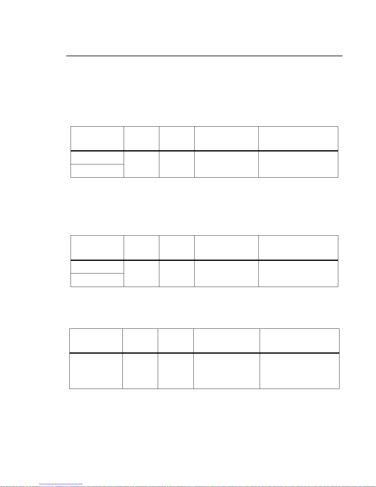
16-bit control of luminaire pan operation.
Table 3-13: DMX Map for Luminaire Pan Operation
DMX Channel % Value
3 (High Byte)
0 - 100 0 - 65535 32768
4 (Low Byte)
DMX
Value
Luminaire Tilt
16-bit control of luminaire tilt operation.
Table 3-14: DMX Map for Luminaire Tilt Operation
DMX Channel % Value
5 (High Byte)
0 - 100 0 - 65535 32768
6 (Low Byte)
DMX
Value
Focus Time
Default - These values
are recommended
console default values
Default - These values
are recommended
console default values
Action
16-bit control of Pan - 540
degrees of movement.
Action
16-bit control of Tilt - 270
degrees of movement.
DMX Channel % Value
20 0 - 100 0 - 255 255
30 15 April 2010 02.9 690.0001 A
Table 3-15: DMX Map for Focus Timing
DMX
Value
Default - These values
are recommended
console default values
Action
Allows for luminaire timing of
pan and tilt. Profile should
default to DMX 255 for
smoothest console fade
times.
Page 47
Luminaire Timing
Timing Channel Information
Timing channel control improves the timed moves of certain groups of parameters. We provide up to
four timing channels, one for focus (Pan and Tilt), one for color parameters, one for beam parameters,
and one for luminaire intensity.
Types of timing control:
• Timing Control Channel: the luminaire uses its timing channel value to calculate a smooth
continuous movement for a given time and transition.
• Console Timing: the console calculates the time duration between the DMX increments to be sent
for a given time and transition.
Guidelines:
• Timing channels support time values of up to six minutes.
• To use a timing channel instead of console timing, it is necessary to set the timing channel to the
desired value and set cue and/or parameter time to zero. A combination of time controls can
produce unexpected results.
OPERATION : LUMINAIRE TIMING
3
• The default value setting in the profile should be 255 (proportional control) to allow smooth
movement when using console timing.
• The timing channel data should change as a snap. A zero value will give the fastest move,
however, without any smoothing this can appear "steppy" in console timed moves.
Table 3-16: VLX Channel Function / Timing Channel Relationship
Channel Function
Focus Time Color Time Beam Time Intensity Time
Pan (Hi Byte/Lo Byte)
Tilt (Hi Byte/Lo Byte)
Red (Hi Byte/Lo Byte)
Green (Hi Byte/Lo Byte)
Blue (Hi Byte/Lo Byte)
White (Hi Byte/Lo Byte)
Beam Spreader
*Intensity
*If Intensity has a timing channel value, manual faders will respond at given time value.This may deliver unexpected results.
Timing Channel
A timing value of zero is full speed. A time value of 100% (or 255 in DMX) enables the associated
parameter(s) to follow cue fade time (console time) rather than the timing channel.
02.9690.0001 A 15 April 2010 31
Page 48

VARI❋LITE® - VLX™ WASH LUMINAIRE USER’S MANUAL
Note: The particular storing syntax for your console, as well as instructions on how to write part cues,
can be found in the operation manual for that console.
To use these channels, you must:
Step 1. Create the cue, including color, focus, intensity, etc. as required.
Step 2. Decide which fixtures and which parameter groups will use timing channels.
Step 3. Assign a value to the particular timing channel(s) you wish to use (for timing information,
see chart on next page).
Step 4. Set console timing (or cue fade time) for parameters and timing channels to zero seconds.
Step 5. Store cue.
Note: Avoid changing timing channel values in a fading cue. This can cause unexpected behavior in
the luminaire as the timing channel value is updated over time. Timing channel values and the final
destination of the parameters affected by the timing channel should always be sent in a zero count.
32 15 April 2010 02.9 690.0001 A
Page 49

OPERATION : LUMINAIRE TIMING
Timing channels can be set in either % or 0-255 (DMX) modes, with the following values assigned:
3
Table 3-17:
% Value DMX = Seconds
130.6
251
381.6
4102
5132.6
6153
7183.6
8204
9234.6
10 25 5
1 1 28 5.6
12 31 6.2
13 33 6.6
14 36 7.2
15 38 7.6
Timing Channels Map
0 Full Speed
10.2
20.4
40.8
61.2
71.4
91.8
11 2.2
12 2.4
14 2.8
16 3.2
17 3.4
19 3.8
21 4.2
22 4.4
24 4.8
26 5.2
27 5.4
29 5.8
30 6
32 6.4
34 6.8
35 7.0
37 7.4
02.9690.0001 A 15 April 2010 33
Page 50

VARI❋LITE® - VLX™ WASH LUMINAIRE USER’S MANUAL
Table 3-17: Timing Channels Map (Continued)
% Value DMX = Seconds
16 41 8.2
17 43 8.6
18 46 9.2
19 48 9.6
20 51 10.2
21 54 11
22 56 12
23 59 13
24 61 14
25 64 15
26 66 16
27 69 17
28 71 18
29 74 19
30 76 20
31 79 21
39 7.8
40 8
42 8.4
44 8.8
45 9
47 9.4
49 9.8
50 10
52 10.4
53 10.6
55 11
57 12
58 13
60 14
62 14
63 15
65 16
67 16
68 17
70 18
72 18
73 19
75 20
77 20
78 21
80 21
34 15 April 2010 02.9 690.0001 A
Page 51

OPERATION : LUMINAIRE TIMING
Table 3-17: Timing Channels Map (Continued)
% Value DMX = Seconds
81 22
32 82 22
83 23
33 84 23
85 23
86 24
34 87 24
88 25
35 89 25
90 25
91 26
36 92 26
93 27
37 94 27
95 27
96 28
38 97 28
98 29
39 99 29
100 29
101 30
40 102 30
103 30
104 31
41 105 31
106 32
42 107 32
108 32
109 33
43 110 33
111 34
44 112 34
113 34
114 35
45 115 35
116 36
46 117 36
118 36
119 37
47 120 37
121 38
48 122 38
3
02.9690.0001 A 15 April 2010 35
Page 52

VARI❋LITE® - VLX™ WASH LUMINAIRE USER’S MANUAL
Table 3-17: Timing Channels Map (Continued)
% Value DMX = Seconds
49 125 39
50 128 40
51 130 41
52 133 42
53 135 43
54 138 44
55 140 45
56 143 46
57 145 47
58 148 48
59 150 49
60 153 50
61 156 51
62 158 52
63 161 53
64 163 54
123 38
124 39
126 39
127 40
129 41
131 41
132 42
134 43
136 43
137 44
139 45
141 45
142 46
144 47
146 47
147 48
149 49
151 49
152 50
154 50
155 51
157 52
159 52
160 53
162 54
164 54
36 15 April 2010 02.9 690.0001 A
Page 53

OPERATION : LUMINAIRE TIMING
Table 3-17: Timing Channels Map (Continued)
% Value DMX = Seconds
165 55
65 166 55
167 56
66 168 56
169 56
170 57
67 171 57
172 58
68 173 58
174 58
175 59
69 176 59
177 59
178 60
70 179 60
180 65
71 181 65
182 65
183 70
72 184 70
185 75
73 186 75
187 75
188 80
74 189 80
190 85
75 191 85
192 85
193 90
76 194 90
195 95
77 196 95
197 95
198 100
78 199 100
200 110
79 201 110
202 110
203 120
80 204 120
205 120
81 206 130
3
02.9690.0001 A 15 April 2010 37
Page 54

VARI❋LITE® - VLX™ WASH LUMINAIRE USER’S MANUAL
Table 3-17: Timing Channels Map (Continued)
% Value DMX = Seconds
82 209 140
83 212 150
84 214 160
85 217 170
86 219 180
87 222 190
88 224 200
89 227 210
90 230 220
91 232 230
92 235 240
93 237 250
94 240 260
95 242 270
96 245 280
97 247 290
207 130
208 140
210 140
211 150
213 160
215 160
216 170
218 180
220 180
221 190
223 200
225 200
226 210
228 210
229 220
231 230
233 230
234 240
236 250
238 250
239 260
241 270
243 270
244 280
246 290
248 290
38 15 April 2010 02.9 690.0001 A
Page 55
OPERATION : LUMINAIRE TIMING
Table 3-17: Timing Channels Map (Continued)
% Value DMX = Seconds
249 300
98 250 300
251 310
99 252 310
253 310
254 310
100 255 Follows Cue Data
3
02.9690.0001 A 15 April 2010 39
Page 56

VARI❋LITE® - VLX™ WASH LUMINAIRE USER’S MANUAL
Updating Software
USB Download and Programming
To download files with a PC equipped with a Universal Serial Bus (USB) port, you need the
VARI ❋LITE® USB Luminaire Programming Kit (28.8500.0054). The USB Luminaire Programming
Kit can be ordered directly from your Authorized VARI❋LITE® Dealer.
The VARI❋LITE® USB Luminaire Programming Kit (28.8500.0054) includes:
•VARI❋LITE® USB Upload Cable (25.9600.0001)
• USB Luminaire Programming Kit CD (87.8500.0002)
•
Instruction Sheet (02.8500.0100)
•VARI❋LITE® carry bag (07.5044.0005)
Computer Requirements for the USB Luminaire Programming Kit
• PC running Windows® 98, 2000, XP, or Vista. Although the USB Luminaire Programming kit
software is not directly compatible with Macintosh® computers, it does run with some Windows
emulators.
• In addition to Windows, your computer must be running IE 5.01 or later, and Microsoft.NET
Framework Version 3.5 (or later), which you can download from http://www.microsoft.com and
search for .NET Framework downloads.
• An available USB 2.0 port on the PC.
USB VLDownloader PC Program and .bin Luminaire Files
The USB VLDownloader program and current .bin files are available from the Product Downloads
page at www.vari-lite.com. Instructions for installing the USB VLDownloader program on your PC
are also available on the Product Downloads page. Use the USB VLDownloader program to transfer
updated versions of the luminaire operating software (.bin files) from your PC to the luminaires.
Note: Refer to instruction sheet 02.8500.0100 for detailed programming instructions for
VARI ❋LITE® luminaires.
40 15 April 2010 02.9 690.0001 A
Page 57
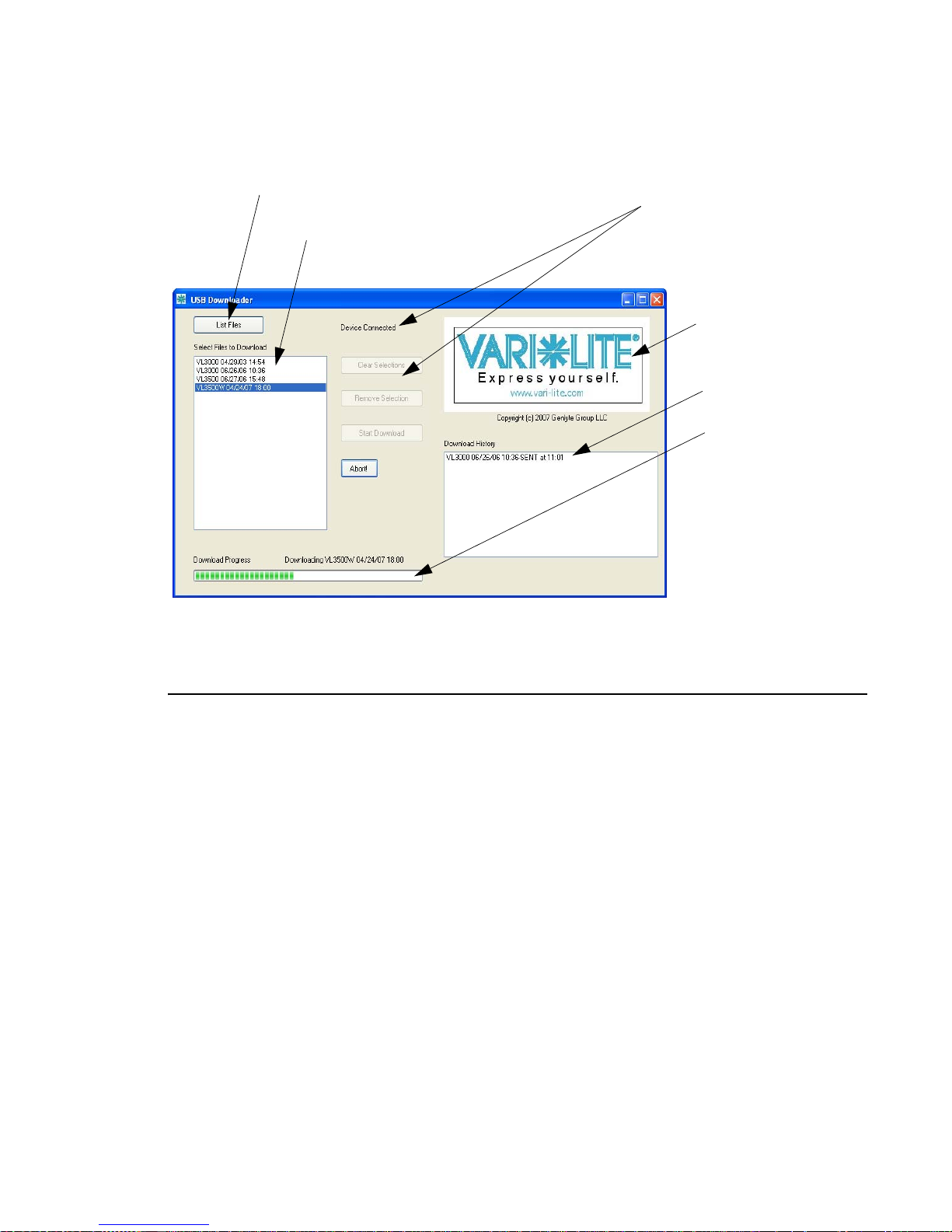
Lists specific versions of
downloaded software (on PC)
Click to download specific software
version to connected luminaire(s)
OPERATION : UPDATING SOFTWARE
3
Device Connection Status and
USB Downloader Controls
Click logo to go to
Vari-Lite web site
(internet connection
required)
Download History
Will show current
progress of download
Figure 3-1: VL Download Program Window
Transferring Software From Luminaire to Luminaire
It is possible to transfer specific software versions between luminaires. As in the case of installing new
software versions, multiple luminaires can be programmed at the same time when they are data linked
together (refer to “Connecting Data and Power” on page 17), however, only a maximum of 32
luminaires can be updated at once.
Hardware Requirements
Data cables used in this process must have two twisted pairs and a shield. It is also recommended that
cables meet all other USITT DMX specification requirements. Refer to “Data Cables” on page 12.
02.9690.0001 A 15 April 2010 41
Page 58
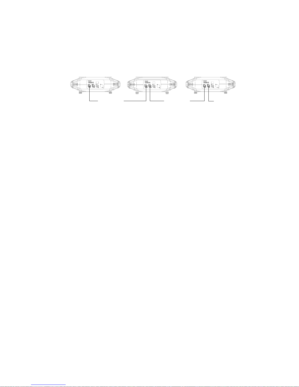
VARI❋LITE® - VLX™ WASH LUMINAIRE USER’S MANUAL
A termination connector is used in this process. Refer to page 13 for more information regarding the
construction of this connector.
Master luminaire containing
software version to download
Data Thru
Luminaire 1
requiring update
Data Thru
Luminaire 2
requiring update
Termination Connector
Figure 3-2: Software Transfer Setup
Transfer Procedure
This procedure is used to transfer software versions between luminaires.
Step 1. At last luminaire, install male termination connector into DATA THRU XLR connector.
Step 2. At master luminaire (first in chain) Menu Display, press [ESC].
Step 3. Press [Up] / [Down] arrows until Fixture appears.
Step 4. Press [Up] / [Down] arrows until Download appears. Press [Enter].
Step 5. OK? will be displayed. Press [Enter] to a ccept.
Step 6. Download proceeds. (Download takes 4-5 seconds.) The number of blocks displayed is less
in a luminaire-to-luminaire download than in a PC-to-luminaire download for the same
software version.
Step 7. When download is complete, luminaire automatically recalibrates. When recalibration is
complete, luminaire is ready for operation with its new software version.
Verify software version at luminaire:
Step 1. At Menu Display, press [ESC].
Step 2. Press [Up] / [Down] arrows until Fixture appears. Press [Enter].
Step 3. Press [Up] / [Down] arrows until Version appears. Press [Enter].
The first half of the version will be displayed as a date (MM.DD.YY). For example,
03.18.03 (March 18, 2003).
Press [Up] / [Down] arrows to display second half of version. This will be displayed as a
time (HH:MM). For example, 16:00
42 15 April 2010 02.9 690.0001 A
Page 59

CHAPTER 4.
Menu System
This chapter contains instructions for operating the luminaire using the Menu Display feature.
For DMX operation and detailed information, see
• Menu Operation
• Menu Functions
“DMX Operation” on page 22.
02.9690.0001 A 15 April 2010 43
Page 60
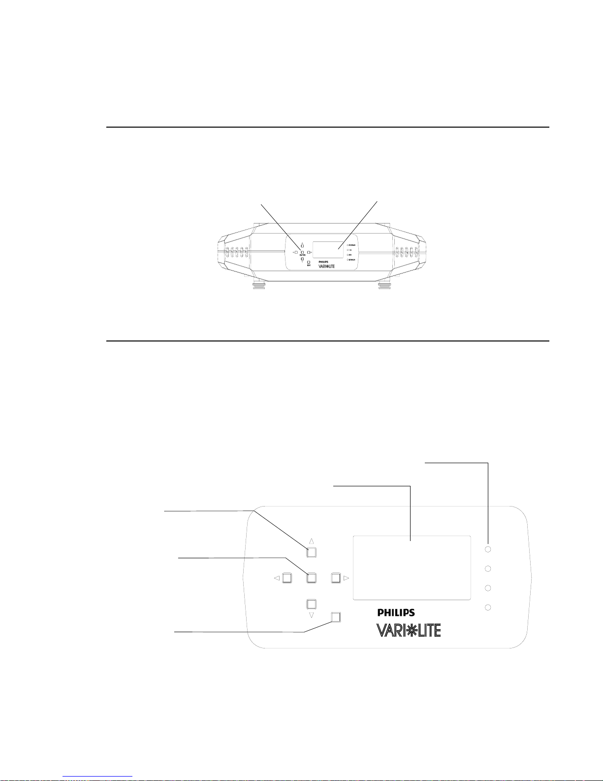
VARI❋LITE® - VLX™ WASH LUMINAIRE USER’S MANUAL
Menu Operation
What Is the Menu System?
The menu system is a programmable set of commands used to configure, address, operate, and test the
luminaire. The menu system is controlled at the Menu Display available at the enclosure input panel.
Enclosure Input Panel
Figure 4-1: Menu Display Location
Menu Display
Controls Operation
The menu system is controlled by an ENTER, ESC (Escape), and four Arrow (YUVZ) buttons.
These buttons function as follows:
Luminaire Status Indicators
(Power On, Transmitting DMX, Receiving DMX, Error in Luminaire Operation)
LCD Display - Displays all Data and Luminaire Settings
Arrow Keys
(Left/Right/Up/Down)
Enter Button
Escape (ESC)
ENTER
ESC
POWER
TX
RX
ERROR
44 15 April 2010 02.9 690.0001 A
Figure 4-2: VLX Menu Control
Page 61
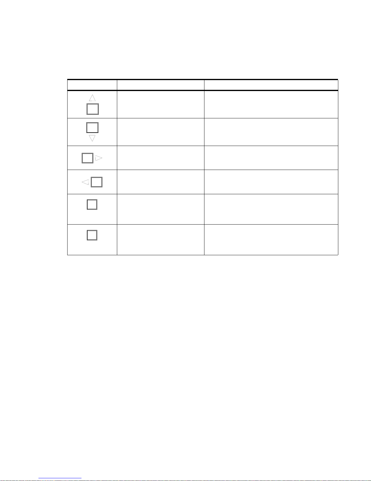
MENU SYSTEM : MENU OPERATION
Table 1-1: Menu Control Buttons
Button Description Action
Up Arrow Menu Navigation / Data Selection
Down Arrow Menu Navigation / Data Selection
Right Arrow Menu Navigation / Data Selection
Left Arrow Menu Navigation / Data Selection
4
Enter Button To Select or Chan ge a Setting or Data Value
ENTER
Escape Button
ESC
Used to Access Main Menu Parameters, Exit, or
Return to Previous Menu Item
[ESC] button. Displays the menu, or if at first level, the current address. Also used to return to
previous menu item or to exit.
[ENTER] button. Selects the current menu option or stores current data value.
[Up] / [Down] / [Left] / [Right] arrows. Scrolls menu options upward or increases current data
value.*
* LCD Display automatically sets to hanging orientation. See Disp Tilt in the “Menu System Func-
tion Chart” on page 48
.
02.9690.0001 A 15 April 2010 45
Page 62

VARI❋LITE® - VLX™ WASH LUMINAIRE USER’S MANUAL
T o enter t he menu system, first press [ES C]. The functions displayed will be 1st level functions. Scroll
through the 1st level functions by pressing [Up] / [Down] arrows. Once the desired function appears in
the display, press [Enter]. You are now at the 2nd level. Once again, press the [Up] / [Down] arrows to
scroll through 2nd level functions. Press [Enter] to access 3rd level functions and so forth. When the
highest level for the function is reached, [Up] / [Down] arrows can be pressed to enter a value or select
a toggle activation such as On/Off. Press [Enter] to store the value or select an action.
For example:
1st Level
Test All Seq RUN TEST
2nd Level 3rd Level
Default State
The menu display’s default state during normal operation is to display the DMX address. After 10
seconds of inactivity at the display, it will change to the default state.
After longer periods of inactivity , th e menu display will switch to its of f state. The default state for this
feature is 5 minutes, however, diff erent time lengths can also be programmed.
To program a different time length for menu off feature:
Step 1. Press [ESC].
Step 2. Press [Up] / [Down] arrows until Config (Configuration) appears. Press [Enter].
Step 3. Press [Up] / [Down] arrows to access Display. Press [Enter].
Step 4. Press [Up] / [Down] arrows to select either 30 Sec (30 seconds), 5 Min (5 minutes), 10
Min (10 minutes), or ON (on indefinitely). Press [Enter] to set.
46 15 April 2010 02.9 690.0001 A
Page 63
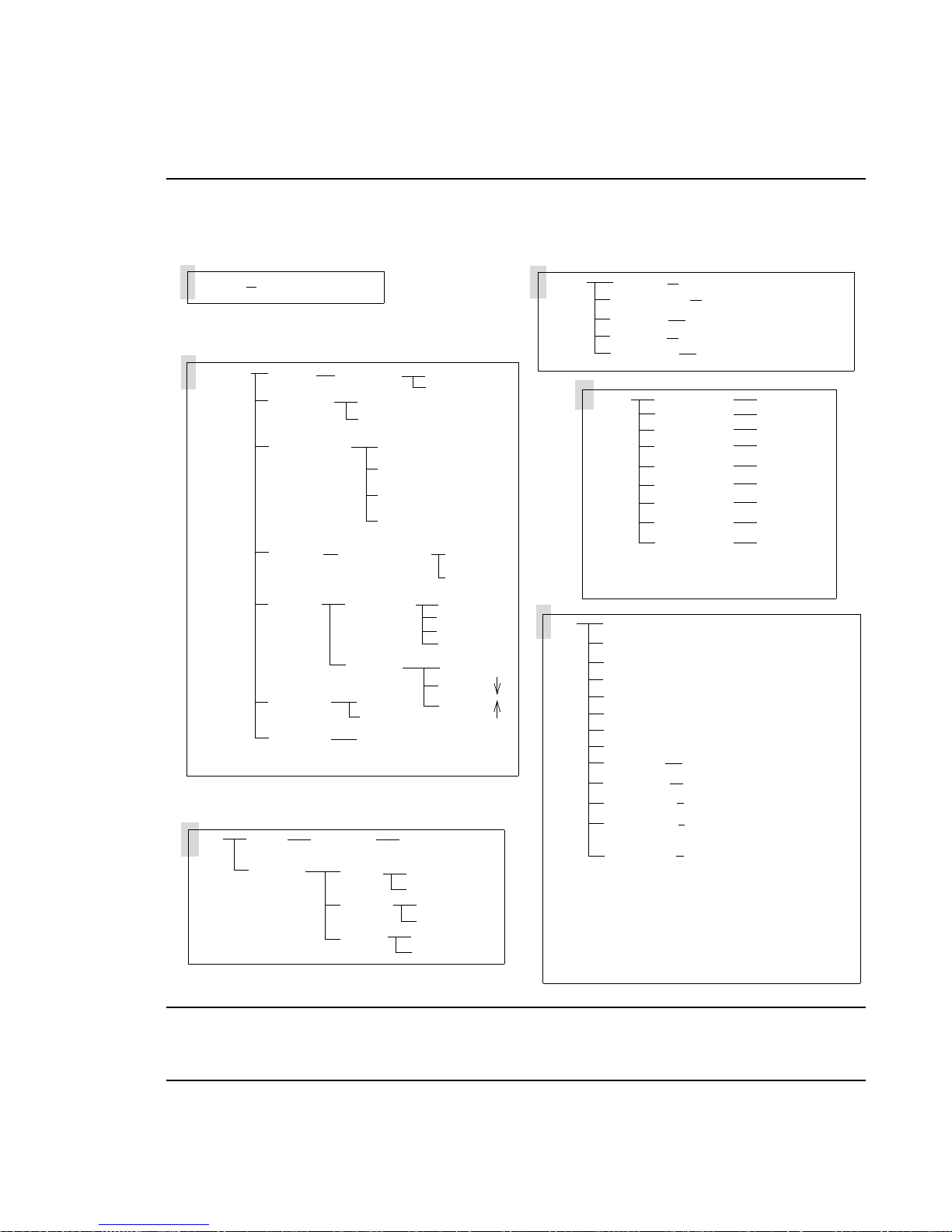
Menu Functions
Menu System Overview
The following is a graphic representation of the entire VLX™ Wash Luminaire menu system.
MENU SYSTEM : MENU FUNCTIONS
4
Address
Configure
DMX
value (1 thru 512)
Pan/Tilt
Dim Curve
Power Level
LED Cal
Display
CMD Lock
Reset Def
Data Chan XXX data
Pan/Tilt
Movement
Square Law
Linear
Normal
Quiet
Constant Fans
Level Light
LED Correction
OFF Time
Disp Tilt
On
Off
OK?
Swap
Inv Pan
Inv Tilt
ON
OFF
ON
OFF
Enable
Disable
ON
OFF
ON
OFF
ON
30 Sec
5 Min
10 Min
Tilt Auto
Display
Display
Fixture
Test
Notes:
Test Mode is disabled if DMX is present.
* LED 5 does not have a fan.
**Do not use RS232 Log unless instructed by Vari-
Lite technical support to do so.
Status
Re-Calibrate
Version
Fixt Hrs
Download
Manual
Note: Manual Mode is disabled if DMX is
present.
All Seq
Pan/Tilt
Pan
Tilt
Strobe
LEDs
Beam Sprdr
Encoder
Int Level Master intensity level
LED Fans Fan Speed 1,2,3,4,6,7*
LED Temps LED Temp 1 thru LED Temp 7
LED Status
RS232 Log On or Off**
scrolls errors or displays OK
OK?
XX/XX/XX (date)
# of hours
OK?
Pan
Tilt
Dimmer
Red
Blue
Green
White
Beam Sprdr
Strobe
LED Status 1 thru
LED Status 7
value
value
value
value
value
value
value
value
value
Note: For the latest version of this manual and luminaire software, please visit the Vari-Lite web site
at www.vari-lite.com and click on the "Product Downloads" link on the VLX™ Was h Lumina ire
Products information page.
02.9690.0001 A 15 April 2010 47
Page 64
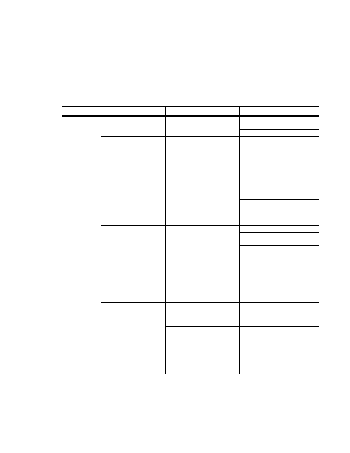
VARI❋LITE® - VLX™ WASH LUMINAIRE USER’S MANUAL
Menu System Function Chart
The following is a detailed look at the internal menu system.
Table 4-1: VLX Wash Menu System Chart
1st Level 2nd Level 3rd Level 4th Level 5thLevel
Address XXX value 1 thru 512
Pan/Tilt
Configure
Fixture
configuration
settings
Pan and Tilt
movement
Dim Curve Fixture dimming
operation
Power Level Settings for
LED operation or calibration
LED Cal Selects whether to
use factory calibration or not
Display Illumination Off Time Selects display off time ON On indefinitely
Display
CMD Lock Selects whether
to set Command Lock - to
lock-out access to various
settings from the console
using the Control Channel
Note: Resetting to Defaults
(DMX 5 - 7 on Control
Channel) will turn Command
Lock OFF.
Reset Default Restores
fixture to factory default
Movement Position recovery Enable
Square Law Dimming curve
(Default)
Linear Standard linear dimming
curve
Power Setup
operation for fans and LEDs
(Note, Quiet will reduce levels to
minimize heat in fixture)
LED Correction Sets LEDs to
factory calibration level
Disp Tilt Display orientation Factory default is Auto and other
functions are currently disabled
from selection.
On Control Channels - Mode,
Dimmer Curve, Color Calibration
(On/Off) - control, via the
console, is disabled.
Off (Default) Control Channels Mode, Dimmer Curve, Color
Calibration (On/Off) - control, via
the console, is enabled.
OK? Asks (confirms) to execute
restoration of factory defaults of
fixture
Four levels of
Disable
Normal Default
Quiet
For reduced
noise
Constant Fans
Sets fans to a set
speed level
Level Sets to a set
level
ON
OFF
Off in 30
30 Sec
seconds
Off in 5
5 Min
minutes
Off in 10
10 Min
minutes
Auto (Default)
Up - Currently
Disabled
Down - Currently
Disabled
48 15 April 2010 02.9 690.0001 A
Menu system description continued on next page.
Page 65
MENU SYSTEM : MENU FUNCTIONS
Table 4-1: VLX Wash Menu System Chart
1st Level 2nd Level 3rd Level 4th Level 5thLevel
DMX
DMX Data
Fixture Status Status/Error Display Scrolls error messages or
Manual
Manual
Commands
(Disabled when
DMX Present.)
DATA Chan XXX DMX Channel XXXX Value 0 - 255
Pan and Tilt
Pan/Tilt
Options
Re-Calibrate Recalibrate
fixture
Version MM/DD/YY (Page 1) HH:MM (Page 2)
Version
Fixt Hrs Fixture Hours XXXX # Number of Fixture Hours
Download
Software
Pan* XXXXX DMX Value
Tilt * XXXXX DMX Value
Dimmer* XXXXX DMX Value
Red* XXXXX DMX Value
Blue* XXXXX DMX Value
Green* XXXXX DMX Value
White* XXXXX DMX Value
Beam Sprdr XXX DMX Value
Strobe XXX DMX Value
Download
Swap Swap Pan & Tilt ON
OFF
Invert Pan ON
Inv Pan
OFF
Invert Tilt ON
Inv Tilt
OFF
OK
displays
OK? Asks (confirms) to execute
recalibration of fixture
OK? Asks (confirms) to
download software in fixture
4
02.9690.0001 A 15 April 2010 49
Menu system description continued on next page.
Page 66

VARI❋LITE® - VLX™ WASH LUMINAIRE USER’S MANUAL
Table 4-1: VLX Wash Menu System Chart
1st Level 2nd Level 3rd Level 4th Level 5thLevel
Test Fixture
operational
tests - Press
[ESC] to stop
tests
All Seq Selects fixture to run
and sequence through all
available tests
Pan/Tilt Selects fixture to
run Pan/Tilt operational test
Pan Selects fixture to run
Pan operational test
Tilt Selects fixture to run Ti lt
operational test
Strobe Selects fixture to run
Strobe operational test
LED Operational test of
each LED operation
Beam Sprdr Selects fixture
to run beam spreader
mechanism operational test
Int Level (Intensity Limiter)
Sets luminaire’s output to
the set percentage of the
operation mode setting.
This is used to match overall
output level of multiple
VLX™ wash luminaires if
desired.
LED Fans Selects and
displays fan speed for
1,2,3,4,6, or 7 (Note: LED 5
does not have a fan)
LED Temps Selects and
displays LED junction
temperature
LED Status Selects and
displays LED status
RS232 Log** Selects
RS232 logging operation
RUN TEST
RUN TEST
RUN TEST
RUN TEST
RUN TEST
RUN TEST
RUN TEST
XXX% (Enter value - up to 100%)
Set Maximum Output Value
Fan X (select fan)
LED Temp 1
LED Status 1
or Off** (SEE NOTE
On
BELOW)
thru LED Temp 7
thru LED Status 7
* For 16-bit parameters, the data displayed will be scaled to a range of 0-65535.
**Do NOT use or select RS232 unless instructed by Vari-Lite techn ical supp ort to do so.
50 15 April 2010 02.9 690.0001 A
Page 67
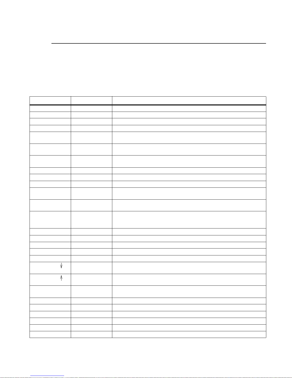
MENU SYSTEM : MENU FUNCTIONS
4
Menu Function Definitions
For easy reference, each possible menu item is listed alphabetically in the first column by its display
abbreviation. The second column follows with a definition of the abbreviation and then a third column
provides an explanation of its purpose and function.
Table 4-2: Menu Function Definitions
Display Definition Purpose
10 Min 10 Minutes Sets Menu Display to automatically shut off after 10 minutes of non-use.
30 Sec 30 Seconds Sets Menu Display to automatically shut off after 30 seconds of non-use.
5 Min 5 Minutes Sets Menu Display to automatically shut off after 5 minutes of non-use.
Address Address Accesses option for setting luminaire DMX starting address.
All Seq All Test
Sequences
Auto Automatic Opera-
tion
Beam Sprdr Beam Spreader
Mechanism
Blue Blue LED Specifies Blue color (intensity) for manual control (Manual).
CAL LEDs Calibrates LEDs To start LED calibration or to set LEDs to specific factory calibration level
Channel XXX DMX Channel Specifies DMX channel for display of current data value.
CMD Lock Command Lock Selects whether to set Command Lock - to lock-out access to various settings
Configure System
Configuration
Constant Fans Fixture Mode Luminaire setup is in Constant Fans mode. This setting sets fans to maximum
Data DMX Data Accesses option for setting DMX address channel.
Dim Curve Dimmer Operation Specifies dimmer to operate in Curve or Linear Mode
Dimmer Dimmer Specifies dimmer mechanism for manual control (Manual).
Disable Disable Disables a function.
Display Display Accesses options for Menu Display illumination time and orientation.
Display Display Selects and sets menu display orientation of arrow direction. (Currently Dis-
Display Display Selects and sets menu display orientation of arrow direction. (Currently Dis-
Disp Tilt Menu orientation
control
DMX DMX Accesses options for DMX system settings.
Download Download Initiates download of luminaire software.
Enable Enable Enables a function.
Encoder Encoder Accesses pan/tilt encoders for diagnostic testing.
FAIL Test Fail Indicates that a test has failed.
Fixt Hrs Fixture Hours Displays total number of hours luminaire has been powered on.
Tests all internal mechanisms in sequence for X steps.
When set to "Auto", menu display will automatically orient itself is relation to
fixture’s hanging or sitting position (up or down).
Specifies beam spread function for manual control (Manual or Test).
from the console using the Control Channel.
Accesses options for pan/tilt operation, LED Setup, dimmer operational set-
tings, and Menu Display defaults.
speed and will keep them operating at full, regardless of LED junction temperatures.
abled)
abled)
Sets the orientation of the menu display to match the luminaire orientation,
(Auto) automatic display orientation, standing (Up) or hanging (Down).
02.9690.0001 A 15 April 2010 51
Page 68
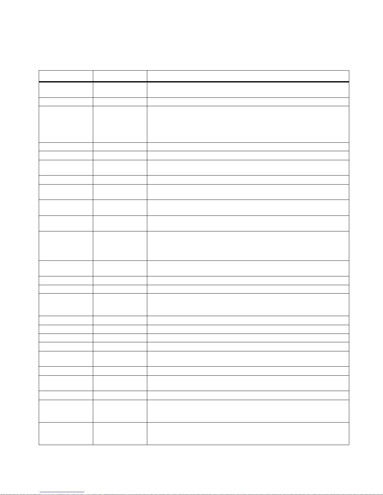
VARI❋LITE® - VLX™ WASH LUMINAIRE USER’S MANUAL
Table 4-2: Menu Function Definitions (Continued)
Display Definition Purpose
Fixture Fixture Accesses luminaire information such as serial number, software version, and
total operation hours. Also accesses recalibration and download options.
Green Green LED Specifies Green (intensity) parameter for manual control (Manual).
Int Level Intensity Level The Intensity Limiter is used to match overall output level of multiple VLX wash
luminaires if desired. The Intensity Limiter default is 100% and is adjustable by
the user. For example, if a fixture’s Intensity Limiter is set to’80’, a value of
100% from a desk will only output 80% of the fixture power (as determined by
the VLX Operation Mode - Normal, Quiet, Constant Fans or Level Light)
Inv Pan Invert Pan Reverses pan action for special focus requirements.
Inv Tilt Invert Tilt Reverses tilt action for special focus requirements.
LED Correction LED Calibration
Level
LED Fans LED Fan Test Specifies one of luminaire’s six fans for status (or current state) information.
LED Setup LED Operational
Settings
LED Status Current Status of
LED
LED Temps LED Operational
Temperature
Level Light Fixture Mode Luminaire setup is in set to Level Light mode by user. This mode maintains a
Linear Dimming Curve -
Linear
Manual Manual Accesses options for luminaire mechanism control by entry of data values.
Movement Movement Enables or disables pan and tilt movement.
Normal Fixture Mode (Default) Luminaire setup is in normal fan and LED operational mode. This
OFF Off Turns off a function.
Off Time Display off time Shows the automatic shut-off time for the menu display.
OK Okay Indicates calibration has completed and no errors have occurred.
OK? Okay? Prompt for pressing [Enter] before an action is executed.
ON On Indefinitely Sets Menu Display to stay on until programmed otherwise (Display) or turns
Pan Pan Specifies pan function for manual control (Manual) or testing (Test).
Pan/Tilt Pan/Tilt Accesses pan and tilt options for focus swap function, movement enable/dis-
PASS Test Pass Indicates that a test has passed.
Programming Luminaire soft-
ware program-
ming
Power Level Fixture operational
power level
Sets LEDs to factory calibration level.
LED settings/operation of power level or calibration.
Specifies one of luminaire’s seven LEDs for status (or current state) information.
Measures temperature associated with LED operation - displays in degrees
Celsius
reduced LED output to keep various fixtures from operating at different levels
depending upon thermal situations. The fans will run full speed, regardless of
junction temperatures.
Sets dimmer operation to standard linear dimming curve. See also, "Square
Law"
mode operates the luminaire’s fans according to the LED's junction temperature. Fans will vary in speed according to thermal readings by MCB.
on a function.
able, manual control and testing.
The luminaire is in the process of being reprogrammed with a new version of
software.
Sets the output of the luminaire to Normal, Quiet (reduced fan operation and
light output), Constant Fans (fans stay at a constant speed, cooling capacity),
or Level (set operational level as desired by user)
52 15 April 2010 02.9 690.0001 A
Page 69
MENU SYSTEM : MENU FUNCTIONS
Table 4-2: Menu Function Definitions (Continued)
Display Definition Purpose
Quiet Fixture Mode Luminaire setup is in Quiet mode. LED output levels are decreased to keep
LED junction temperatures lower and fan noise to a minimum. Fans will still
vary in speed, but will not exceed the set (lower noise) limit.
Re-Calibrate Recalibrate Recalibrates luminaire.
Red Red LED Specifies Red (intensity) for manual control (Manual).
Reset Def Reset Defaults Resets default system configuration values.
RS232 Log RS232 Logging
WARNING: For factory use only - DO NOT use OR select, "RS232
Log - > On" unless instructed by Vari-Lite technical support to do so.
RUN TEST Run Test Indicates that a mechanism test is in prog ress.
SENS TST Sensor Test Indicates that a system sensor test is in progress.
Square Law Dimming Curve -
Square Law
Start LED CAL Factory Use Only
Sets dimmer operation to Square Law dimming curve. See also, "Linear"
WARNING: For factory use only - DO NOT use OR select, "Start
LED Cal".
4
Status Status/Error Allows scrolling through error list or displays OK if no errors.
Strobe Manual strobe
operation
Swap Swap Swaps pan/tilt action for special focus requirements.
Test Test Accesses diagnostic tests for internal mechanisms or assemblies.
Tilt Tilt Specifies tilt function for manual control (Manual) or testing (Test).
Version Version Displays current software version date and time (in two pages).
White White LED Specifies White (intensity) parameter for manual control (Manual) or testing
Allows (Manual) operation of luminaire strobe.
(Test).
02.9690.0001 A 15 April 2010 53
Page 70

VARI❋LITE® - VLX™ WASH LUMINAIRE USER’S MANUAL
Notes
54 15 April 2010 02.9 690.0001 A
Page 71
APPENDIX A.
Troubleshooting and
Maintenance
This appendix provides instructions for troubleshooting and routine maintenance which may be
necessary during the life of the luminaire.
• Troubleshooting
• Routine Maintenance
WARNING: All routine maintenance procedures are to be performed with power completely
removed from the luminaire. Never remove protective covers when luminaire is powered. Wear
appropriate protective eye wear and gloves when servicing the fixture. All service and
maintenance, other than described herein should be performed by an Authorized VARI❋LITE
Dealer or Service Center.
®
WARNING: DO NOT connect or disconnect energized power cable at fixture (under load). Turn
off circuit breaker (or completely de-energize circuit) before connecting or disconnecting power
cable at fixture. Power is only removed from the fixture by disconnecting power cable from
source or turning off source circuit breaker.
02.9690.0001 A 15 April 2010 55
Page 72
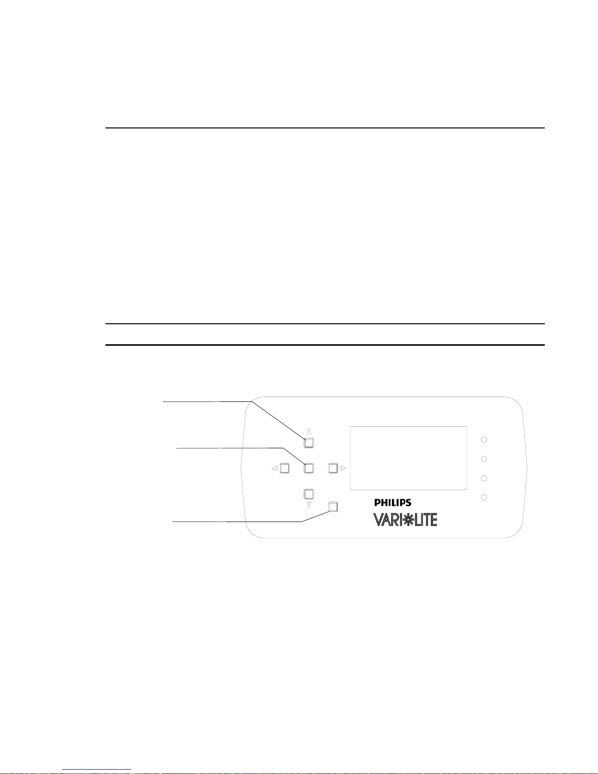
VARI❋LITE® - VLX™ WASH LUMINAIRE USER’S MANUAL
Troubleshooting
Error Messages
If a problem occurs during luminaire calibration, at the end of the calibration sequence the Menu
Display cycles through any applicable error message(s) until the end of the list is reached. To review
the error messages again, re-access them using the Status function.
To access error messages:
Step 1. As indicated in Figure A-1, press [ESC] to access the main menu screen.
Step 2. Press [Up] / [Down] arrows until Fixture appears. Press [Enter].
Step 3. Press [Up] / [Down] arrows to access Status. Press [Enter]. (Display will now scroll
through any error messages or display OK if no errors.)
Step 4. If an error occurs, recalibrate fixture. If error message persists, then contact an Authorized
VARI ❋LITE
® Dealer or Service Center for support.
Note: Refer to “Error Message Reference Chart” on page 57 for Errors Message and possible causes.
Arrow Keys
(Left/Right/Up/Down)
Enter Button
Escape (ESC)
FIXTURE
ENTER
ESC
POWER
TX
RX
ERROR
Figure A-1: VLX Wash LCD Display (Menu)
56 15 April 2010 02.9 690.0001 A
Page 73

TROUBLESHOOTING AND MAINTENANCE
Table A-1: Error Message Reference Chart
Error Message Definition Possible Causes
Error X of X
No LED Upload
Board Number X
Error X of X
No LED Comm
Board Number X
Error x of x
LED Overtemp
Board Number x
Error x of x
No LED Config
Board Number x
Error x of x
LED Comm Error
Board Number x
Error x of x
Thermal Fault
Board Number x
Error x of x
No Sensor on Tilt
Error x of x
Encoder Error on Pan
Error x of x
Encoder Error on Tilt
Firmware version in LED Driver Board
did not match firmware version in MCB.
MCB will try to upload correct version of
firmware three times. If, after the third
try the versions do not match, the error
will be displayed.
No response to the MCB from the LED
Driver Board.
LED thermistor is measuring a temperature over 120° C at LED x.
LED Driver Board X has lost its configuration. Configuration is needed to load
currents, limits, logic, etc. LED module
will not turn on without being configured.
LED Driver Board X detected a communication error with MCB.
Open or shorted LED Thermistor.
Tilt sensor flag fails to see optical sensor.
Pan encoder value fails to change during calibration.
Tilt encoder value fails to change during
calibration.
• Faulty LED Driver Board
• Faulty connection between LED Driver Board and Motherboard
• Faulty Motherboard
• Faulty comm between MCB and Motherboard (Multiple Errors)
• Faulty MCB (Multiple Errors)
• Faulty LED Driver Board.
• Faulty connection between LED Driver Board and
Motherboard.
• Faulty Motherboard.
• Faulty comm between MCB and Motherboard (Multiple Errors).
• Faulty MCB (Multiple Errors)
• Faulty Fan
• Faulty LED Driver Board (fan driver)
• High ambient operating temperature
• Faulty LED Driver Board
• Faulty LED Driver Board.
• Faulty connection between LED Driver Board and
Motherboard.
• Faulty Motherboard.
• Faulty comm between MCB and Motherboard (Multiple Errors).
• Faulty MCB (Multiple Errors)
• Faulty LED
• Conductive debris (i.e., graph foil) shorting across LED
Thermistor
• Solder bridge at Thermistor leads on Driver board
• Faulty Tilt Driver (No Movement)
• Faulty Tilt Belt (No Movement)
• Faulty Ti lt Motor (No Movement)
• Faulty Ti lt Sensor (Movement of tilt to stop)
• Faulty Tilt Sensor wiring (Movement of tilt to stop)
• Faulty Tilt Encoder PCB (Movement of tilt to stop)
• Tilt sens or tab not passing through sensor (yoke damage)
• Faulty Pan Driver (No Movement)
• Faulty Pan Belt (No Movement)
• Faulty Pan Motor (No Movement)
• Faulty Pan Encoder (Movement of pan to stop)
• Faulty Pan Encoder wiring (Movement of pan to stop)
• Pan encoder wheel not passing through encoder (pan motor
assembly)
• Faulty Tilt Driver (No Movement)
• Faulty Tilt Belt (No Movement)
• Faulty Ti lt Motor (No Movement)
• Faulty Tilt Encoder (Movement of tilt to stop)
• Faulty Tilt Encoder wiring (Movement of tilt to stop)
• Tilt encoder wheel not passing through encoder (tilt motor
assembly)
A
02.9690.0001 A 15 April 2010 57
Page 74
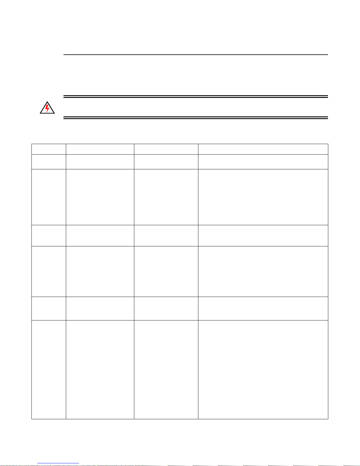
VARI❋LITE® - VLX™ WASH LUMINAIRE USER’S MANUAL
Troubleshooting Guide
If a problem is suspected, first try recalibrating the luminaire to prompt an error message. The chart
below provides possible causes and remedies for various error messages and/or symptoms.
WARNING: All service and maintenance (including troubleshooting), other th an described herein
should be performed by an Authorized VARI❋LITE® Dealer or Service Center.
Table A-2: Troubleshooting Chart
Message Description Symptom Possible Cause/Remedy
n/a No light output Fixture will not produce
or output light
n/a No power Luminaire does not
power up
n/a DMX Data Input Self tests will not run or
software download does
not work.
n/a DMX Failure No response to DMX
data
n/a DMX Termination Erratic control of
luminaire
n/a LED (light) is getting dim-
mer.
Fixture appears not to
be operating at full
brightness.
Component Failure...
- check fans for proper connection and operation.
Circuit not energized...
- verify circuit breaker is turned on.
Not plugged in...
- ensure A/C cable is connected to power source.
Power cable wired incorrectly...
- verify power cable and connector are wired
correctly. (
See “Power and Data Cabling
Requirements” on page 10.
Detecting DMX data...
- disconnect DMX input cable.
MCB connector disconnected...
- check MCB DATA IN connection.
DMX data cable not wired correctly or has a broken
conductor...
- check DMX data cable for proper wiring. (
“Power and Data Cabling Requirements” on
page 10.
No DMX termination or termination not correct...
- check for DMX terminator. (
)
Termination Connector” on page 13.
Luminaire has detected an over temperature
condition...
- The luminaire will reduce power to all 7 LEDs if it
senses that one LED is operating over the
specified temperature. LED temperature is read
and recorded through a thermistor imbedded in
each LED chip. The two yellow wires carry the
information (on temperature) to the LED’s
respective driver PCB.
- Check the thermistor temperatures of each LED
through the fixture’s LCD display.
If one LED is much hotter than the others...
- Check to see that the LED’s fan is running /
connected to the Driver PCB (Note, LED Driver
PCB number 5 does not have a fan) OR,
).
See
See “Male
)
58 15 April 2010 02.9 690.0001 A
Page 75

TROUBLESHOOTING AND MAINTENANCE
Table A-2: Troubleshooting Chart (Continued)
Message Description Symptom Possible Cause/Remedy
n/a Colors (light output) not
matching from luminaire
to luminaire
Color output not matching other VLX Wash fixtures operating at same
control settings.
Calibration turned On or Off...
- Check fixture calibration setting. Make sure
calibration is set to same setting (On or Off) as
other fixtures.
- Check dimming curve setting. Make sure
dimming curve selection (Linear or Curve) is
same for all fixtures.
A
02.9690.0001 A 15 April 2010 59
Page 76
VARI❋LITE® - VLX™ WASH LUMINAIRE USER’S MANUAL
Routine Maintenance
Introduction
Being a solid-state fixture, and unlike most automated arc or tungsten fixtures, the VLX™ Wash
Luminaire requires very little routine maintenance by the user. This section covers all the parts or
assemblies that can be removed, cleaned, and checked by the user. Any additional maintenance or
service should only be completed by an Authorized VARI❋LITE
Special Cleaning and Care Instructions
The VLX™ Wash Luminaire requires special care when it comes to cleaning front lens assembly.
Note: Additional care needs to be taken with the plastic components because they are much easier to
scratch or damage than glass.
® Service Center.
The following is a list of cleaning materials required to care for your VLX™ Wash Luminaire:
• Lint free lens tissue
• Lint free cotton swabs (for hard-to-reach spot cleaning)
• Lint or powder free gloves
• Reagent grade isopropyl alcohol
• A mild soap solution.
Reagent grade isopropyl alcohol is good to use on the VLX™ Wash Luminaire plastic optics with anti-
reflection coatings.
If the lens is still dirty after using isopropyl alcohol, for instance if fingerprints or oil is just
redistributed and not cleaned off the optic, then a mild soap and water solution can be used to gently
wash the lens. Repeat the cleaning with isopropyl alcohol to eliminate streaks and soap residue.
WARNING: Under no circumstances should ammonia-based cleaners, acetone, or other harsh
solvents be used on or near the VLX™ Wash Luminaire. These types of cleaners or solve nts can
permanently damage the optics or housings of the fixture.
If you have any questions regarding the use or care of your VLX™ Wash Luminaire, please contact
Vari-Lite technical support at 1.877-VARI-LITE or +1.214.647.7880.
60 15 April 2010 02.9 690.0001 A
Page 77
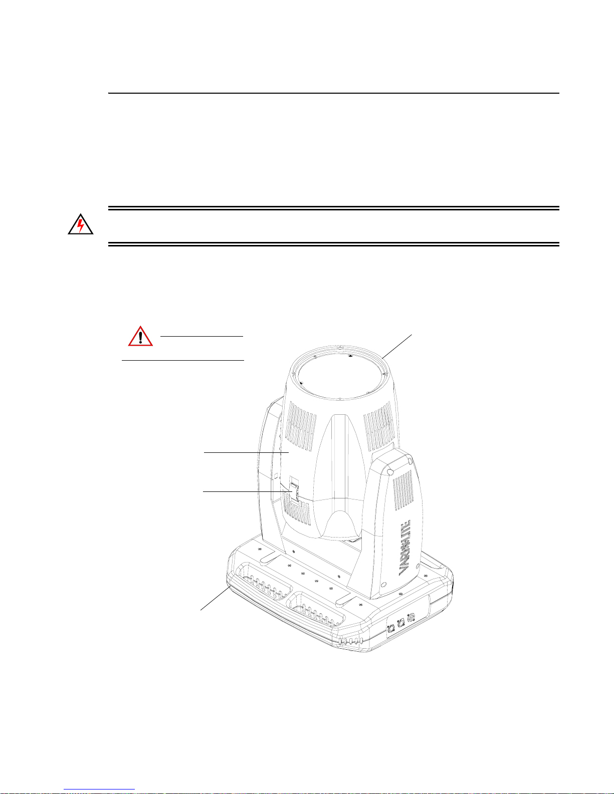
TROUBLESHOOTING AND MAINTENANCE
A
Front Lens R emoval and Cleaning
Tools:
• #2 Phillips screwdriver
• Slotted Screwdriver
• Refer to the list of cleaning materials in “Special Cleaning and Care Instructions” on page 60
WARNING: Ensure that power is completely removed from luminaire before attempting any work.
Always wear eye protection and proper gloves when performing this procedure.
To clean from lens assembly and optics:
Step 1. Remove power from luminaire and allow unit to completely cool.
Step 2. Carefully set luminaire on upper enclosure, rotate head as shown in Figure A-2, and engage
tilt lock.
Luminaire Head
Remove power and
CAUTION:
allow fixture to cool.
Front Head Cover
Front Cover Latch
(one on each side of cover)
Upper Enclosure
Figure A-2: VLX™ Wash Luminaire
Step 3. Remove front head cover by unlatching both head cover latches. Please note that one side of
front cover is secured by a safety tether. Locate clip attached to luminaire and unclip tether.
02.9690.0001 A 15 April 2010 61
Page 78
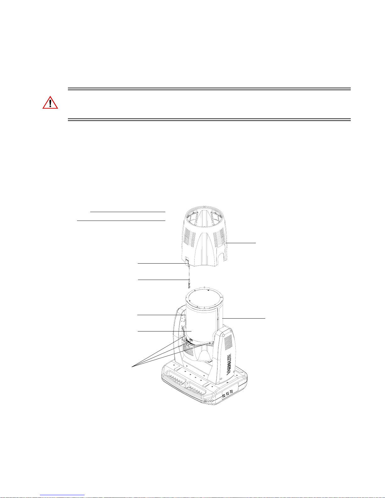
VARI❋LITE® - VLX™ WASH LUMINAIRE USER’S MANUAL
Step 4. Gently slide front head cover over optic assembly and set aside.
Step 5. Optional - only if equipped with long (old-style) EM shields, remove protective EMI shields
from around optics assembly as shown in Figure A-3 as follows:
WARNING: On one EMI shield, it is imperative to identify the ambient temperature sensor that
protrudes through the EMI protective shield (it is on the opposite side where the front cover safety
tether connects. When this shield is removed, great care has to employed not to damage the sensor.
a. At EMI shield (side where front cover safety tether connects), remove all screws
securing cover. Be sure to note locations of removed screws in relation to EMI shield.
b. Remove shield and set aside.
c. At other EMI shield (side with ambient temperature sensor), remove all screws securing
cover. Be sure to note locations of removed screws in relation to EMI shield.
d. Carefully work shield over ambient temperature sensor taking care not to snag or pull
sensor. Once shield is clear of sensor, set shield aside.
Note:
Some components not shown for clarity.
Front Cover Latch
(one on each side of cover)
Front Head Cover
Safety Tether
4-40 x 1/4" PPZ
SEMS Screws (x3)*
EMI Protective Shield
(side with front cover
tether connects to head)
6-32 x 1/4" PPZ
SEMS Screw*
Figure A-3: Front Head Cover and EMI Shields Removal
Front Head Cover
EMI Protective Shield
(side with ambient
temperature sensor)
* Per shield.
Step 6. At head assembly, as shown in Figure A-4, remove front lens assembly as follows:
62 15 April 2010 02.9 690.0001 A
Page 79
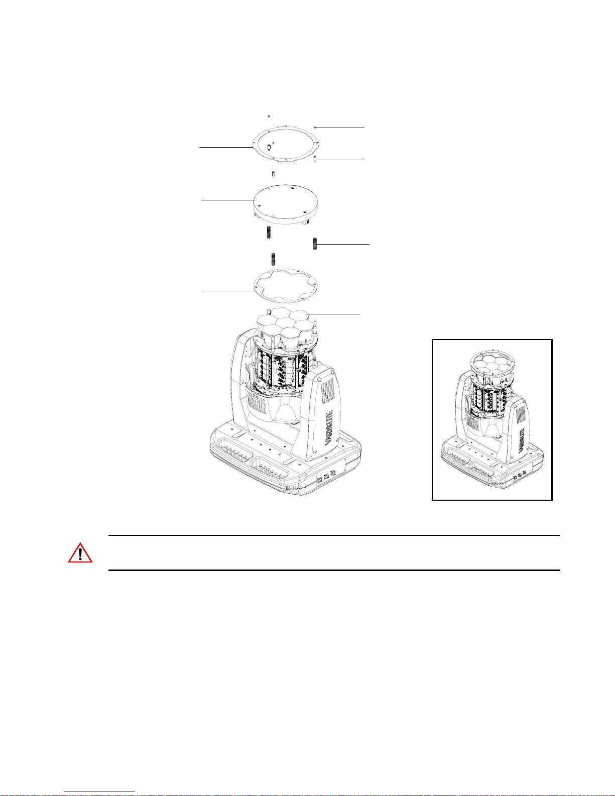
Front Lens Ring
Array Lens
Optics Ring Plate
TROUBLESHOOTING AND MAINTENANCE
A
6-32 x 1/4" PPB Screws (x3)
Zoom Slide Standoffs (x3)
Compression Springs (x3)
Optics (CPC) Lenses
Note: Before proceeding, please note orientation of both front lens ring and front lens assembly. They
must be mounted in their original orientation/position for the front head cover to reinstall properly.
a. Remove three screws securing array lens and lens ring. Set components aside.
b. Note zoom motor wiring and routing. Disconnect wiring from zoom motors.
c. At front lens, loosen and remove and remove three stand-offs. Remove lens and place
lens on a clean, lint free cloth as not to damage or scratch lens.
d. Remove three compression springs and optic ring plate. Set components aside.
Step 7. Clean front lens and optics according to the guidelines set forth in “Spe c i al Clea n i ng an d
Care Instructions” on page 60.
02.9690.0001 A 15 April 2010 63
Figure A-4: Front Lens Removal
Page 80
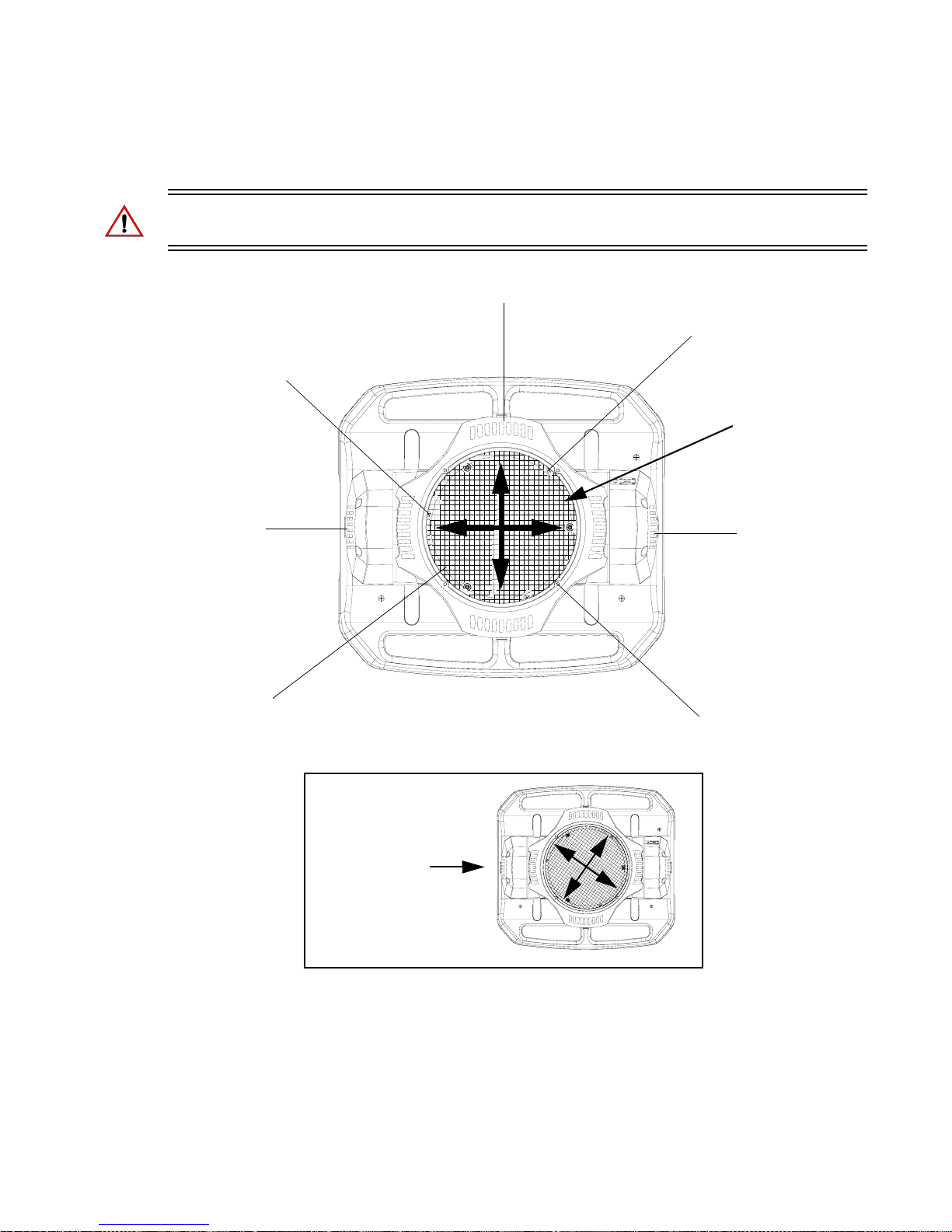
VARI❋LITE® - VLX™ WASH LUMINAIRE USER’S MANUAL
Step 8. Once cleaning is complete, reassemble by performing Steps 6 through 2 in reverse order. Be
sure to orient front lens as shown in Figure A-5.
WARNING: Front Lens Assembly must be mounted in orientation show. If installed incorrectly,
luminaire performance will be affected.
Luminaire Head
Front Lens Ring
Mounting Screw
Front Lens Ring
Mounting Screw
Correct Front
Lens Assembly
Orientation
Yoke Arm
Front Lens
Yoke Arm
Front Lens Ring
Mounting Screw
Incorrect Front
Lens Assembly
Orientation
Step 9. When reinstalling front head cover , be sure not to let cover edge come in contact with optics
(CPC) lenses.
Step 10. Once luminaire is reassembled, power and test.
64 15 April 2010 02.9 690.0001 A
Figure A-5: Front Lens Orientation
Page 81
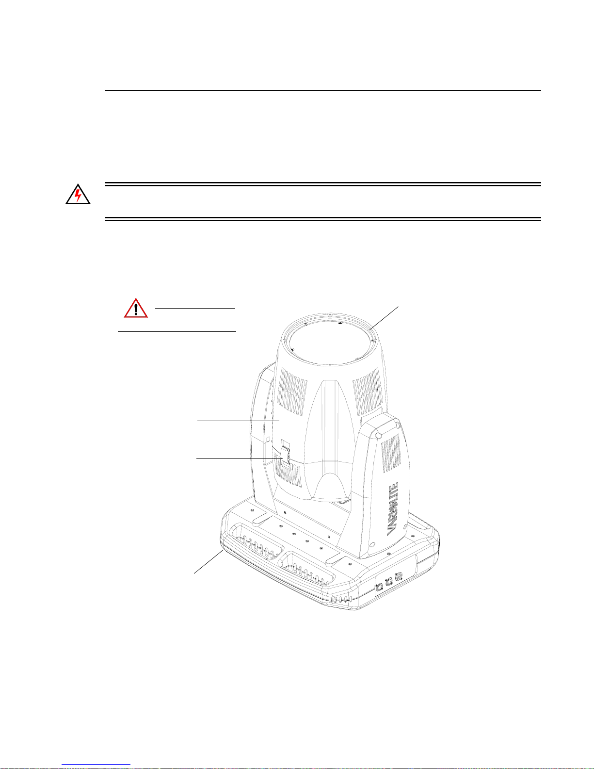
TROUBLESHOOTING AND MAINTENANCE
A
Beam Spreader Removal for Fixed Beam Applications
Tools:
• #2 Phillips screwdriver
• Slotted screwdriver
WARNING: Ensure that power is completely removed from luminaire before attempting any work.
Always wear eye protection and proper gloves when performing this procedure.
To remove beam spreader assembly for fixed beam applications:
Step 1. Remove power from luminaire and allow unit to completely cool.
Step 2. Carefully set luminaire on upper enclosure, rotate head as shown in Figure A-2, and engage
tilt lock.
Luminaire Head
Remove power and
CAUTION:
allow fixture to cool.
Front Head Cover
Front Cover Latch
(one on each side of cover)
Upper Enclosure
Figure A-6: VLX™ Wash Luminaire
Step 3. Remove front head cover by unlatching both head cover latches. Please note that one side of
front cover is secured by a safety tether. Locate clip attached to luminaire and unclip tether.
Step 4. Gently slide front head cover over optic assembly and set aside.
02.9690.0001 A 15 April 2010 65
Page 82
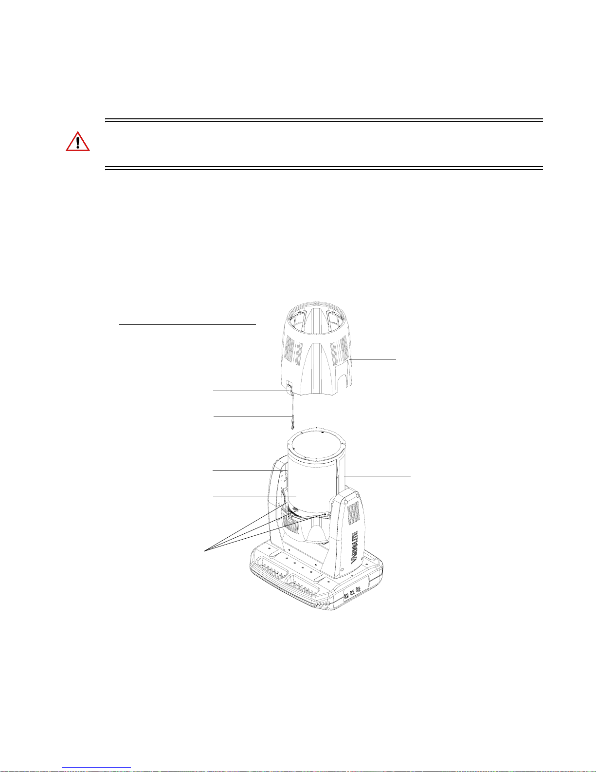
VARI❋LITE® - VLX™ WASH LUMINAIRE USER’S MANUAL
Step 5. Optional - only if equipped with long (old-style) EM shields, remove protective EMI shields
from around optics assembly as shown in Figure A-3 as follows:
WARNING: On one EMI shield, it is imperative to identify the ambient temperature sensor that
protrudes through the EMI protective shield (it is on the opposite side where the front cover safety
tether connects. When this shield is removed, great care has to employed not to damage the sensor.
a. At EMI shield (side where front cover safety tether connects), remove all screws
securing cover. Be sure to note locations of removed screws in relation to EMI shield.
b. Remove shield and set aside.
c. At other EMI shield (side with ambient temperature sensor), remove all screws securing
cover. Be sure to note locations of removed screws in relation to EMI shield.
d. Carefully work shield over ambient temperature sensor taking care not to snag or pull
sensor. Once shield is clear of sensor, set shield aside.
Note:
Some components not shown for clarity.
Front Head Cover
Front Cover Latch
(one on each side of cover)
Front Head Cover
Safety Tether
4-40 x 1/4" PPZ
SEMS Screws (x3)*
EMI Protective Shield
(side with front cover
tether connects to head)
6-32 x 1/4" PPZ
SEMS Screw*
EMI Protective Shield
(side with ambient
temperature sensor)
Figure A-7: Front Head Cover and EMI Shields (Long Style Only) Removal
* Per shield.
66 15 April 2010 02.9 690.0001 A
Page 83
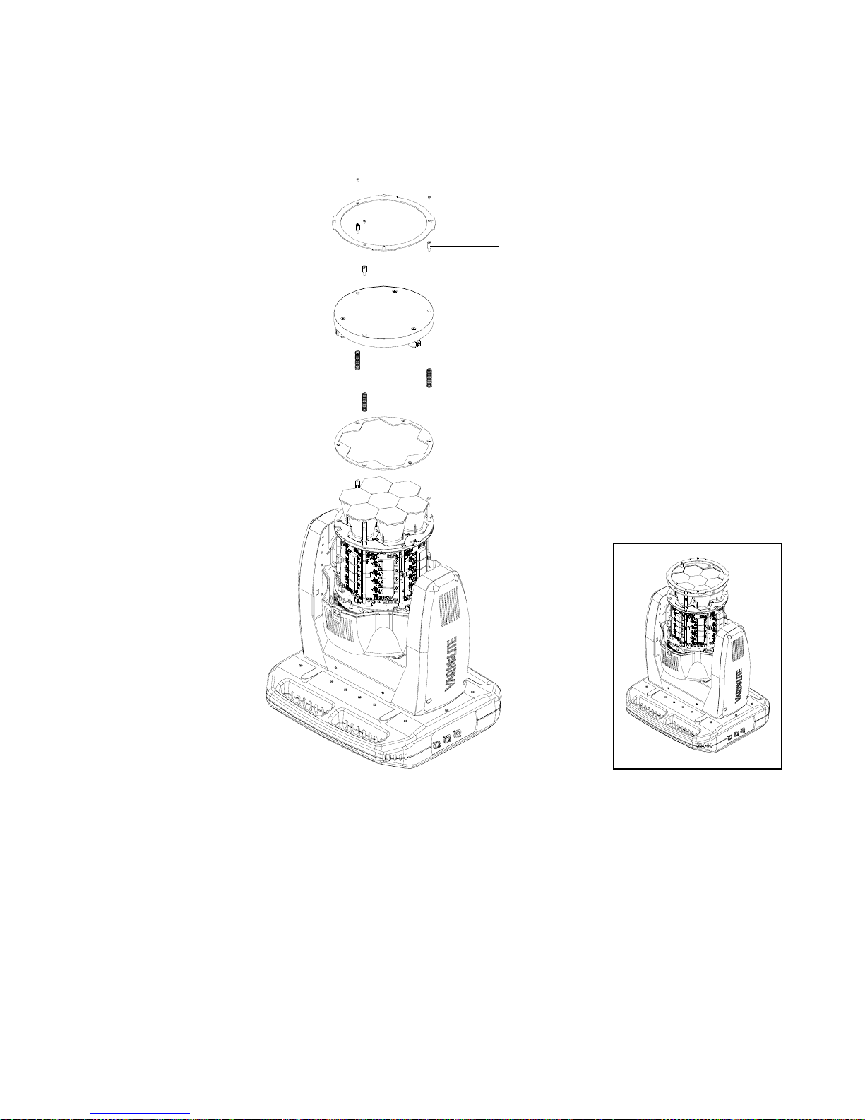
TROUBLESHOOTING AND MAINTENANCE
Step 6. At head assembly, as shown in Figure A-4, remove front lens assembly as follows:
6-32 x 1/4" PPB Screws (x3)
Front Lens Ring
Zoom Slide Standoffs (x3)
Array Lens
Compression Springs (x3)
Optics Ring Plate
A
a. Remove three screws securing array lens and lens ring. Set components aside.
b. Note zoom motor wiring and routing. Disconnect wiring from zoom motors.
c. At front lens, loosen and remove and remove three stand-offs. Remove lens and place
lens on a clean, lint free cloth as not to damage or scratch lens.
d. Remove three compression springs and optic ring plate. Set components aside.
Step 7. Reassemble luminaire for fixed beam applications as follows:
02.9690.0001 A 15 April 2010 67
Figure A-8: Front Lens Removal
Page 84
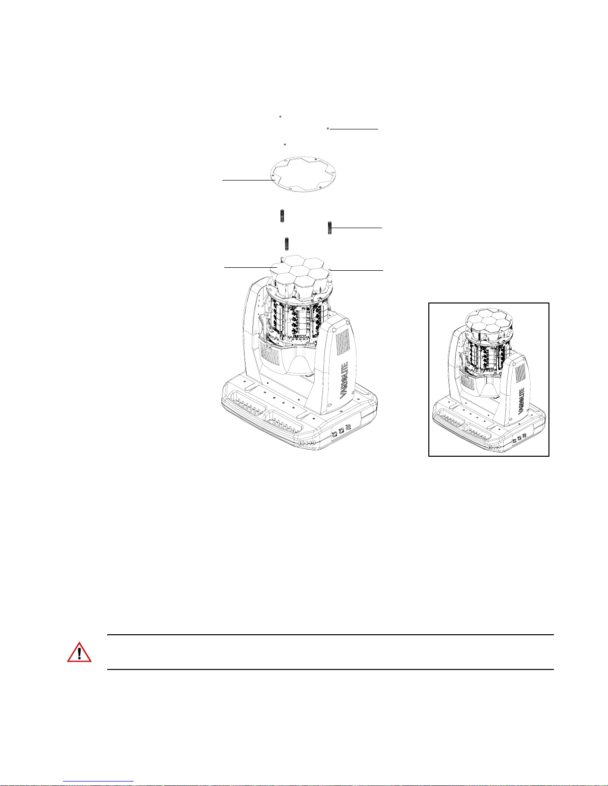
VARI❋LITE® - VLX™ WASH LUMINAIRE USER’S MANUAL
Optics Ring Plate
6-32 x 1/4" PPB Screws (x3)
Compression Springs (x3)
Optics (CPC) Lenses (x7)
Figure A-9: Fixed Beam Application Assembly
a. As shown in Figure A-9 , slide compression springs over optics assembly posts.
b. Turn optics ring (60
does not slide over optics (CPC) lenses.
c. Using three 6-32 x 1/4" PPB screws, secure Optics Ring Plate to assembly.
Optics Assembly Posts (x3)
o
) so its mounting holes are in line with optics assembly posts but
Step 8. Reinstall EMI protective shields. Use care when installing EMI shield on side of ambient
temperature sensor as not to damage sensor.
Step 9. Reinstall front head cover. Be sure not to let cover edge come in contact with optics (CPC)
lenses.
Step 10. Once luminaire is reassembled, power and test.
Note: Carefully store front lens in a soft lint-free, non-abrasive covering for future use. Be sure to
keep all parts (removed with front lens) with front lens in a separate container (as not to damage lens).
68 15 April 2010 02.9 690.0001 A
Page 85
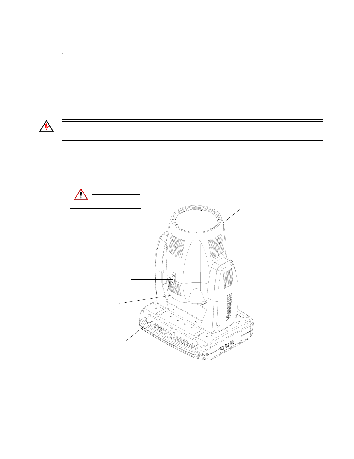
TROUBLESHOOTING AND MAINTENANCE
A
Cooling System Heatsink Cleaning Procedure
Tools:
• #2 Phillips Screwdriver
• Moisture and oil-free, compressed air duster
• Soft bristle, 1" Mottler brush
WARNING: Ensure that power is completely removed from luminaire before attempting any work.
Always wear eye protection and proper gloves when performing this procedure.
To clean the cooling system heatsinks:
Step 1. Remove power from luminaire and allow unit to completely cool.
Step 2. Carefully set luminaire on upper enclosure, rotate head as shown in Figure A-10, and engage
tilt lock.
Remove power and
CAUTION:
Front Head Cover
(one on each side of cover)
Rear Head Cover
allow fixture to cool.
Front Cover Latch
Upper Enclosure
Luminaire Head
Step 3. Remove front head cover by unlatching both head cover latches. Please note that one side of
front cover is secured by a safety tether. Locate clip attached to luminaire and unclip tether.
02.9690.0001 A 15 April 2010 69
Figure A-10: VLX Wash Luminaire
Page 86
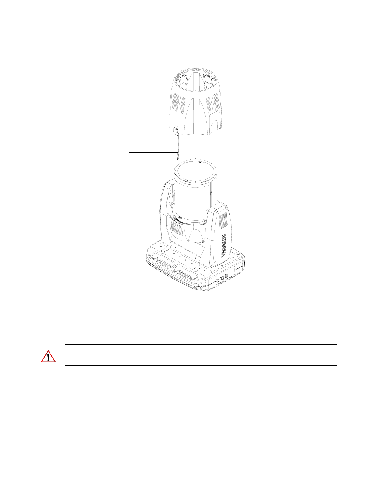
VARI❋LITE® - VLX™ WASH LUMINAIRE USER’S MANUAL
Step 4. Gently slide front head cover over optic assembly and set aside.
Front Cover Latch
(one on each side of cover)
Front Head Cover
Safety Tether
Front Head Cover
Step 5. Disengage tilt lock and rotate luminaire head 90-degrees and re-engage tilt lock (optional).
Step 6. At inside of rear head cover, remove eight #6 x 1/4" PPZ Plastic Threading Screws and
remove rear head cover and set aside.
Note: At reinstalling rear head cover, be careful not to over tighten plastic threading screws (plastic
mounting holes may crack).
70 15 April 2010 02.9 690.0001 A
Figure A-11: Front Head Cover Removal
Page 87
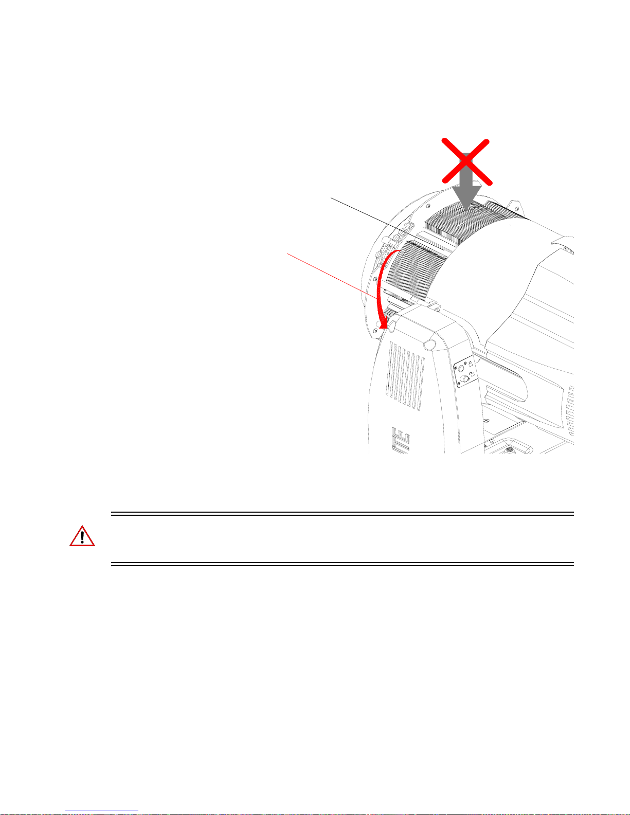
TROUBLESHOOTING AND MAINTENANCE
A
Step 7. As indicated in Figure A-12, at LED cooling assembly heatsinks, run Mottler brush gently
through and in the direction of the heatsink fins from top to bottom so debris will fall down
and away from assembly. Care should be taken as not to damage heatsinks.
NOTE: Do not direct compressed air
through the heatsinks (towards fans)
LED Cooling Assembly Heatsinks
Remove any debris in direction
of heatsink fins (top to bottom)
Figure A-12: VLX Wash Cooling System Heatsink Cleaning
Step 8. Using compressed air duster, blow any remaining debris from heatsink fins in the same
direction as indicated in previous step.
WARNING: DO NOT direct compressed air through heatsinks towards fans or vice-versa. Doing so
will cause the fans to spin at a high rate and could damage them. Also, never use any type of cleaning
solution on heatsinks.
Step 9. Reassemble luminaire by following Steps 3 through 6 in reverse order.
Step 10. Power luminaire and test.
02.9690.0001 A 15 April 2010 71
Page 88

VARI❋LITE® - VLX™ WASH LUMINAIRE USER’S MANUAL
Notes
72 15 April 2010 02.9 690.0001 A
Page 89
APPENDIX B.
Technical
Specifications
VLX™ Wash Luminaire
PROGRAMMABLE FUNCTIONS
Color Mixing System
Seven, custom replaceable 120 watt RGBW LED chipsets.
Each chipset contains high density red, green, blue, and white
LED emitters.
Zoom Optics
Patented optical zoom system with continuously variable field angle
from approximately 23° to 58°. Zoom module is easily removable for
fixed field angle of 22°.
Intensity Control
Smooth, high resolution dimming control of Red (R), Green (G), Blue (B), and White (W) LED’s.
Strobe
High speed with multiple strobe effects.
Pan and Tilt
Smooth, time-controlled continuous motion by way of a pair of three-phase stepper motor
systems. Pan range is 540°/ Tilt range is 270° both with a 0.3° resolution.
OPTICAL
Source
Seven x 120 watt RGBW chipsets.
Color Temp. White: Variable between approximately 3000 and 9000 Kelvin.
CRI: Dynamically Adjustable.
Manufacturer Rated Life: In excess of 10,000 hours (at full RGBW).
Output
14,000 lumens (white light).
NOTE: Vari-Lite reserves the right to change details of design, materials and finishes.
Specifications are subject to change without notice. VARI
is made in the U.S.A.
❋LITE® automated lighting equipment
02.9690.0001 A 15 April 2010 73
Page 90
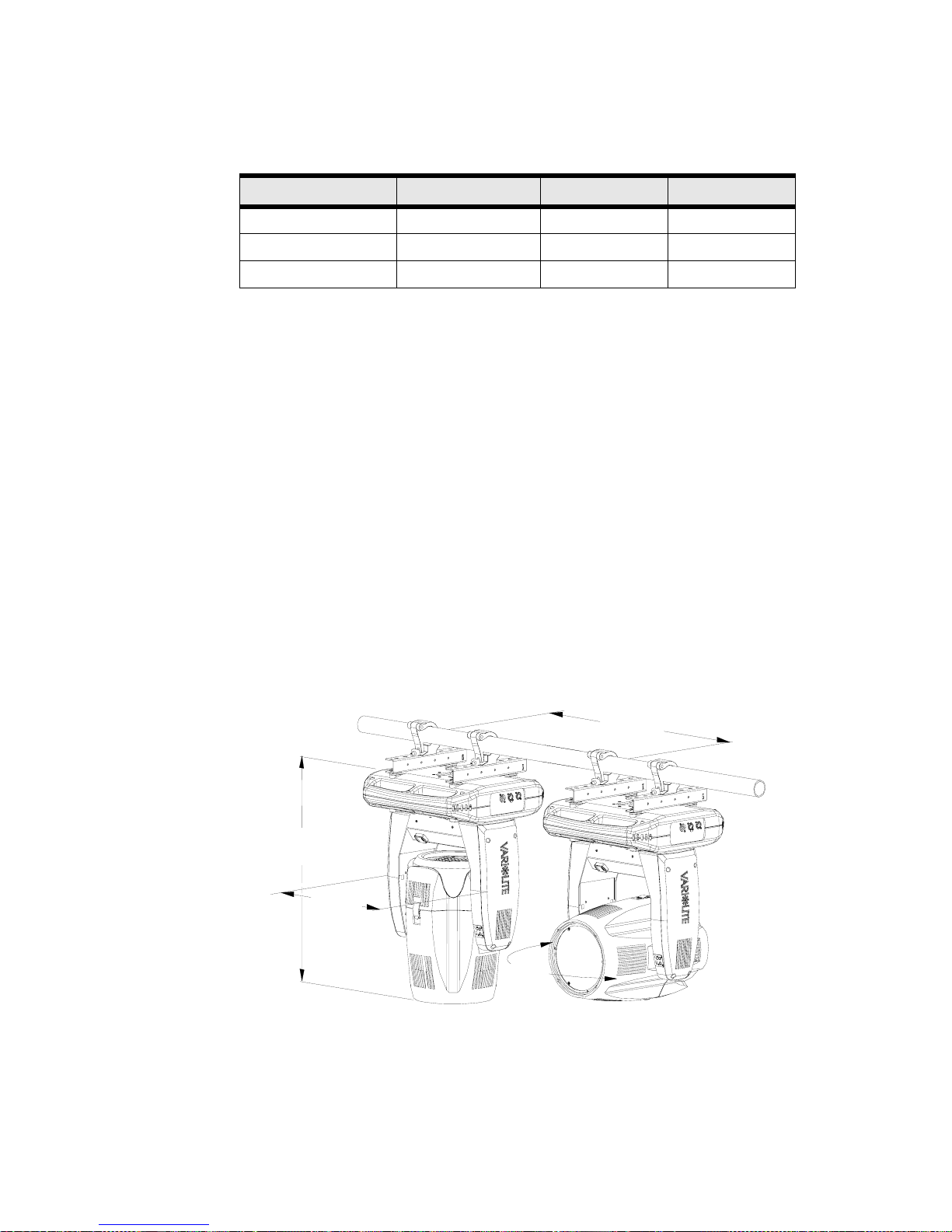
VARI❋LITE® - VLX™ WASH LUMINAIRE USER’S MANUAL
PHOTOMETRIC
Zoom LED Mode Field Angle Lumens
Narrow RGBW
Wide RGBW
Without Lens Array RGBW
OPERATIONAL
Power Requirements
Standard AC power distribution from 100-240 VAC, 50/60 Hz. The fixture requires up to 10A
depending on the AC supply voltage.
Operational Temperature
-20° to 122°F (-29° to 50°C)
Cooling
Variable forced air cooling.
Control
Completely compatible with a wide variety of DMX512 lighting control consoles. 23 channels. 5-pin in
and thru DMX.
Weight
62 lbs. (28.2 kg) with included pair of hanging rails.
Spacing
Hangs on 22.0 inch (559 mm) centers. All models can be mounted and operated in any orientation.
23
58
22
o
o
o
12,200
10,900
13,900
27.4 in
696.0 mm
445.0 mm
22.0 in
559.0 mm
(on centers)
17.5 in
21.5 in
546.0 mm
74 15 April 2010 02.9 690.0001 A
Page 91
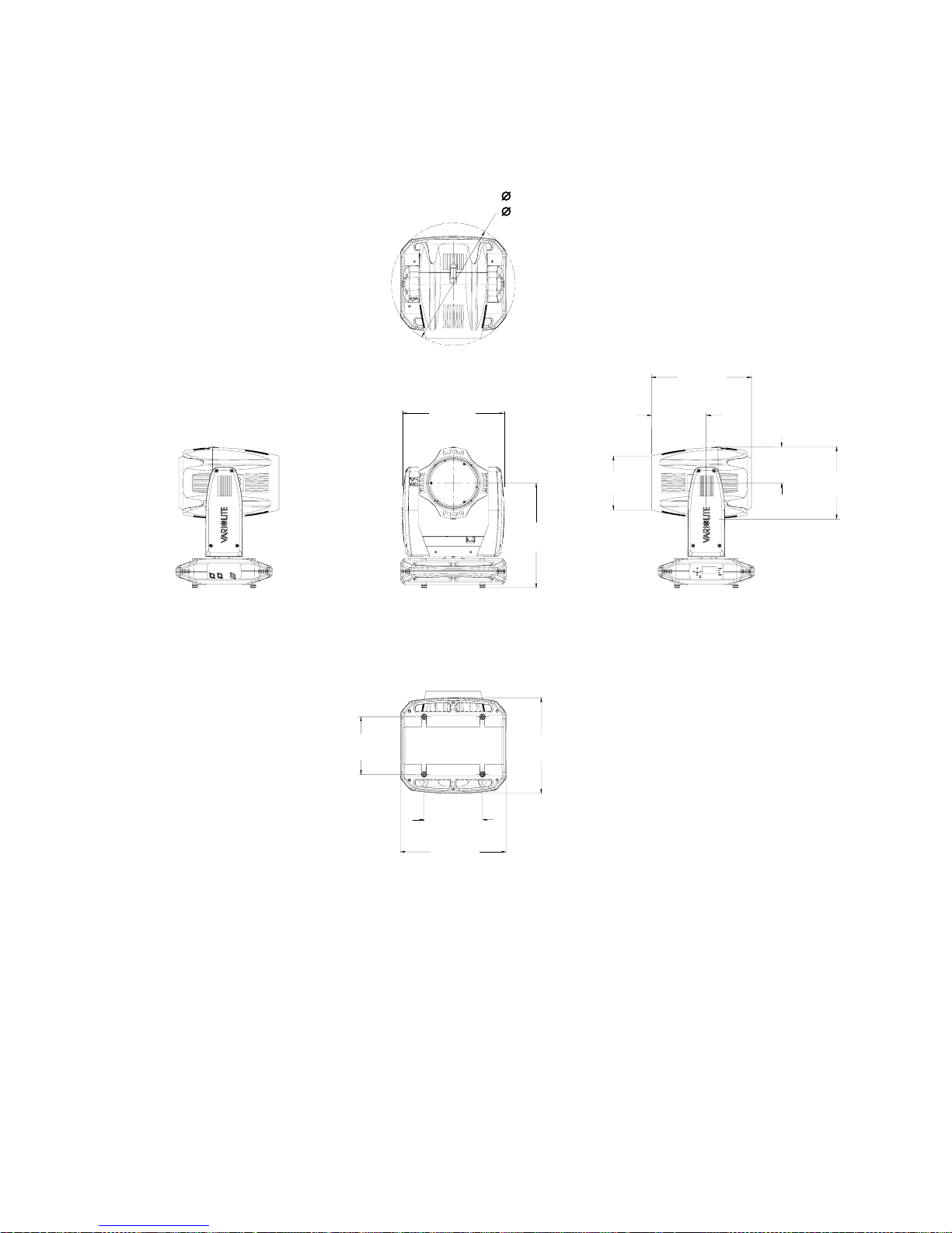
Dimensions
17.47 in
443.8 mm
21.50 in
546.1 mm
TECHNICAL SPECIFICATIONS
17.17 in
436.1 mm
9.42 in
239.2 mm
9.38 in
238.1 mm
159.6 mm
6.28 in
B
12.53 in
318.4 mm
10.00 in
254.0 mm
10.00 in
254.0 mm
18.16 in
461.2 mm
18.21 in
462.5 mm
16.58 in
421.2 mm
02.9690.0001 A 15 April 2010 75
Page 92

VARI❋LITE® - VLX™ WASH LUMINAIRE USER’S MANUAL
Notes
76 15 April 2010 02.9 690.0001 A
Page 93

Page 94

©2009 - 2010 Vari-Lite, a Philips group company. All Rights Reserved.
Vari-Lite
10911 Petal Street
Dallas, Texas 75238 USA
1-877-VARI-LITE ❋ 1-214-647-7880
www.vari-lite.com.
 Loading...