

Page 1
CAUTION
R
ISK OF ELECTRIC SHOCK.
DO NOT OPEN.
CAUTION:
REFER SERVICING TO QUALIFIED PERSONNEL.
Video RF Modulator
Owner’s Manual
INTRODUCTION
Your Video RF Modulator is designed to convert the separate audio and
video signals (from a video camera, computer, portable VCR, satellite
receiver, DVD player, etc.) into normal VHF TV signals that you can see on
any regular TV set.
Warning:
expose this product to rain or moisture.
For indoor use only; to reduce risk of fire or shock hazard, do not
This symbol is intended to alert you to the presence of
uninsulated dangerous voltage within the RF
Modulator’s enclosure that might be of sufficient
magnitude to constitute a risk of electric shock. Do not
open the RF Modulator’s case.
This symbol is intended to inform you that important
operating and maintenance instructions are included
in the literature accompanying this RF Modulator.
Page 2
THE FCC WANTS YOU TO KNOW
This device complies with Part 15 of the
to the following two conditions: (1) This device may not cause harmful
interference, and (2) this device must accept any interference received,
including interference that may cause undesirable operation.
Even under optimum conditions, your Video RF Modulator may cause
undesirable interference. We suggest the following methods for trouble
shooting
1. Use an AC outlet that is not the same circuit as the receiver.
2. Place the RF Modulator in a location further away from your receiver.
In the event that interference still occurs after the above steps have been
taken, you are required by FCC regulations to discontinue use of this
:
FCC Rules
. Operation is subject
product.
Important Safety Information
1. Before beginning installation of your Video RF Modulator read all
instructions and follow exactly throughout the installation.
2. After installation is complete, keep all instructions in a safe place so
they may be referred to in the future if necessary.
3. Please note the ideal environment for this device is on a hard flat
surface away from all heat sources and moisture.
:
Page 3
PARTS REQUIRED
ANT IN
TO TV
LR
60Hz/4.5W
V
IN
S-VIDEO
Jack Jack
S-Video OutputVideo Output
OR
Video Source
You need the following items, not supplied with your Video RF Modulator,
to connect it between a video input source (video game, video camera,
satellite receiver, DVD player, etc.) and your TV.
• Two 75-ohm coaxial cables with F-type connectors
• If your TV does not have a VHF 75-ohm F-connector, you will also
need a 75-ohm-to-300-ohm matching transformer
•One video shielded cable with RCA Plugs and one audio (stereo)
cable with RCA Plugs OR Dubbing Cable for VCR/DVD with RCA
Plugs OR 3 shielded cables with RCA Plugs
•One S-Video Cable
CONNECTIONS
Follow these steps to connect your RF Modulator:
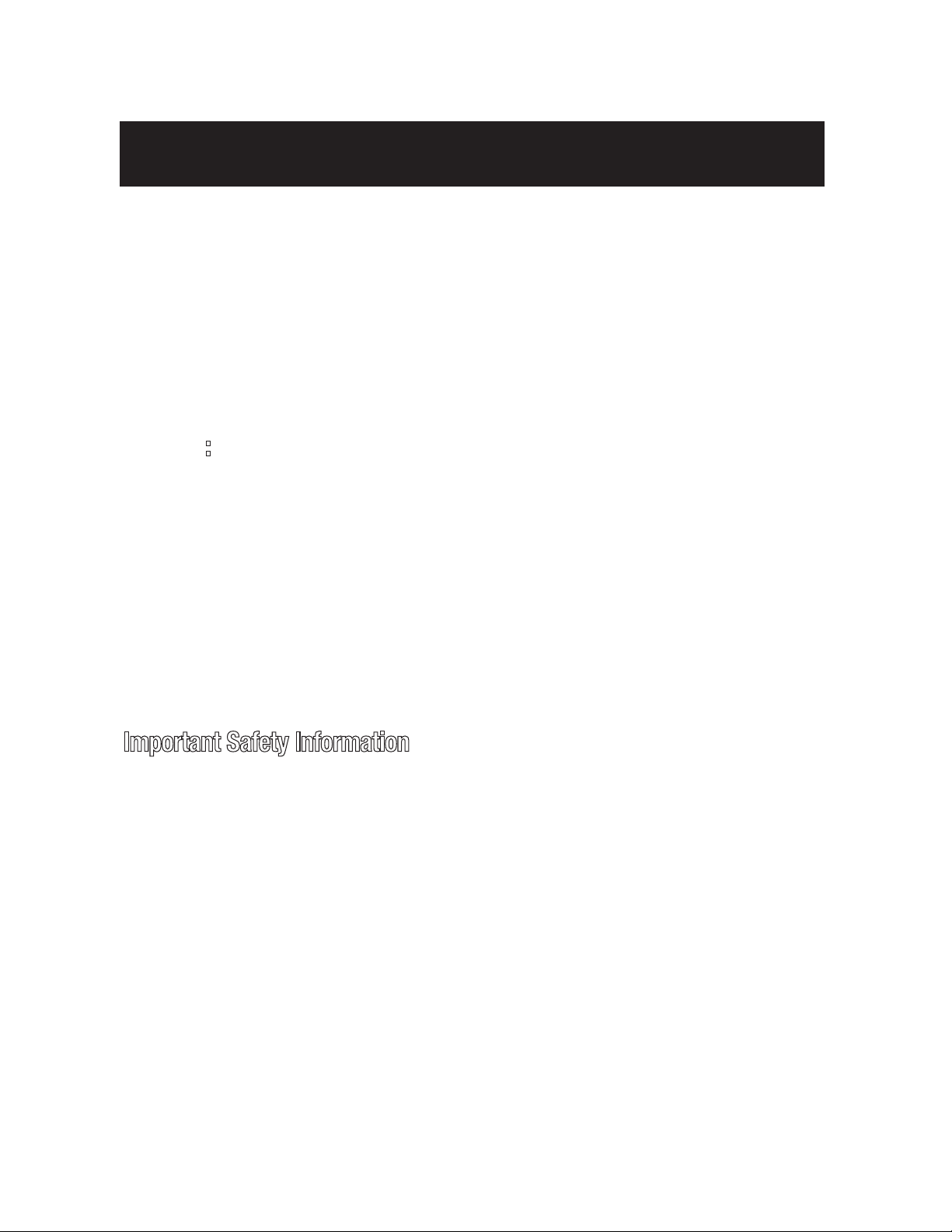
1. Connect an S-Video or video cable between the S-Video or video output
jack on your video source and the RF Modulator’s
S-VIDEO
VIDEO IN
or
jack.
Note:
If both the S-Video and standard video are hooked up,
the S-Video will be given priority
Page 4
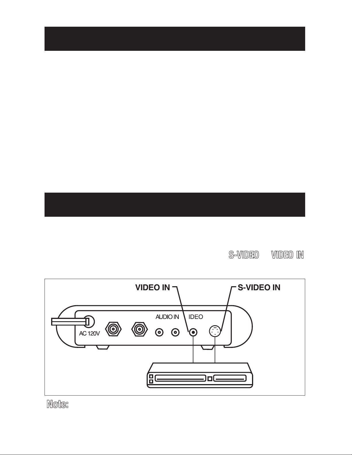
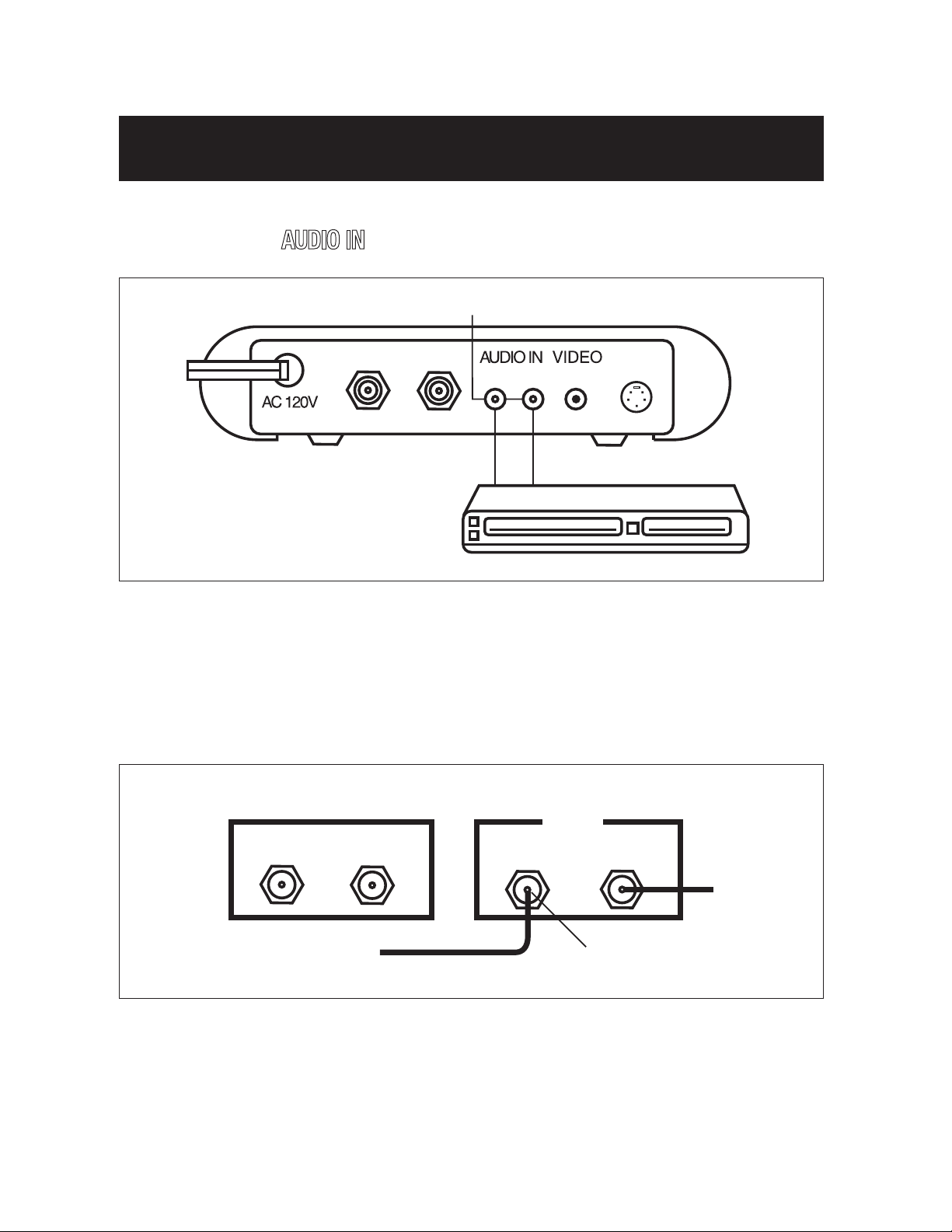
2. Connect an audio cable between the audio output jacks on your video
AUDIO IN Jacks
Audio Output
Audio Source
ANT IN
TO TV
LR
60Hz/4.5W
IN
S-VIDEO
TO TV
CATV/ANT
VHF
RF Modulator VCR
ANT INT mhO 57VT O 75 Ohm
Disconnect
from here
source and the RF Modulator’s
AUDIO IN
jacks.
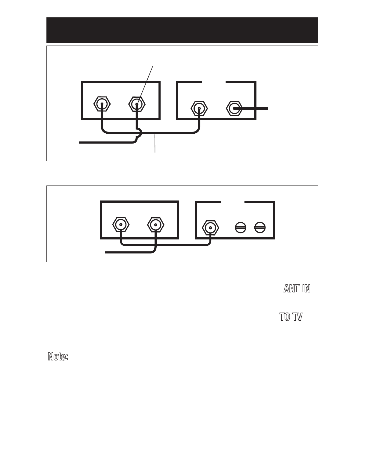
3. Connect the 75-ohm coaxial cables to the RF Modulator using one of
these two (2) options:
Option 1: If your TV is already connected to another VHF input source
(such as cable TV,VCR, etc.):
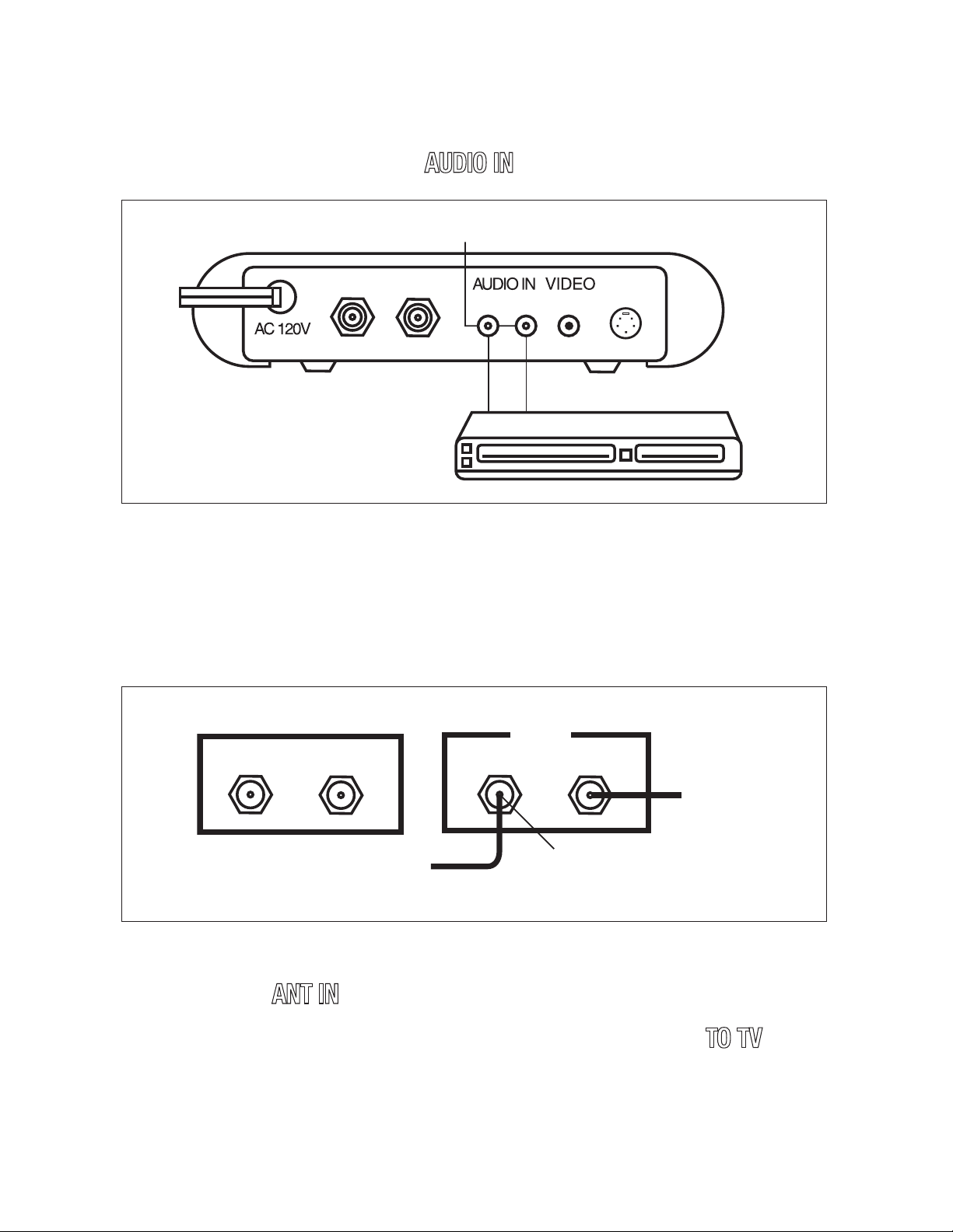
a. Disconnect the current CATV/antenna connection from the 75-ohm
input terminal of your VHF source, and reconnect it to the RF
Modulator’s
ANT IN
b. Then add a 75-ohm coaxial cable connected between the
terminal of the RF Modulator and the 75-ohm input terminal of your
VHF source.
terminal.
TO TV
Page 5
7
5 Ohm
CATV
3
00 Ohms
VHF
RF Modulator TV
ANT INTO TV
CONNECTIONS continued
75 Ohm75 Ohm
OUTIN
CATV
VHF
Add this cable
Reconnect
here
RF Modulator VCR
ANT INTO TV
TO TV
Option 2: If your TV is not already connected to another VHF source:
a. Disconnect the current CATV/antenna cable from the 75-ohm input
terminal of your TV, and reconnect it to the RF Modulator’s
terminal.
b. Then add a 75-ohm coaxial cable connected between the
terminal of the RF Modulator and the 75-ohm VHF input terminal on
your TV.
Note:
to-300-ohm matching transformer to complete the connection.
If your TV has only 300-ohm VHF screw terminals, use a 75-ohm-
4. Plug the RF Modulator’s power cord into a standard AC outlet.
ANT IN
TO TV
Page 6
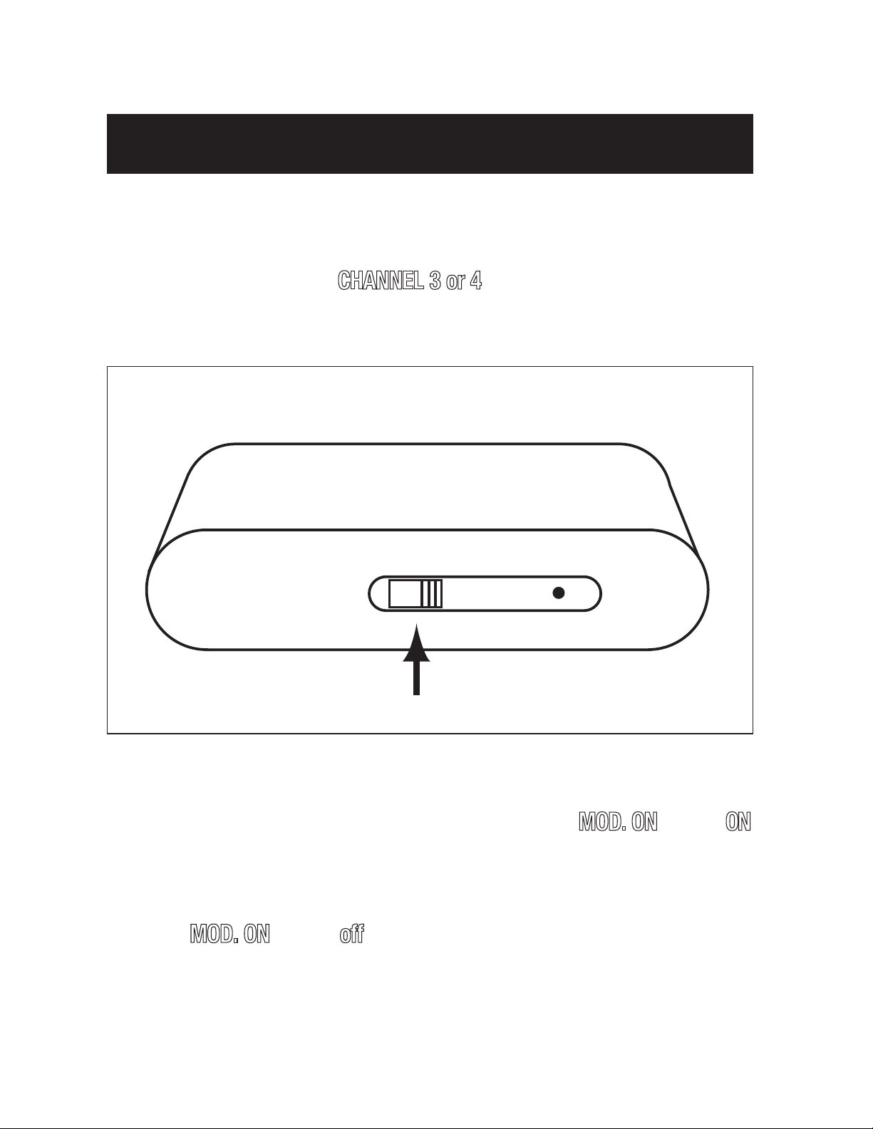
OPERATION
4
3
MOD. ON
CHANNEL
1. Turn on the TV and set it to either Channel 3 or 4, whichever of the
two is not used for regular broadcasts in your area.
2. Set the RF Modulator’s
you set on the TV (3 or 4)
CHANNEL 3 or 4
switch to the same channel
3. Turn on the connected video source, the modulator will deliver the
video/audio signal to the TV set and the red light of
Turn off the connected video source, the modulator will be switched
4.
MOD. ON
will be ON.
automatically to deliver the ANT/Cable signal to the TV set and the red
led of
MOD. ON
will be
off
.
Page 7
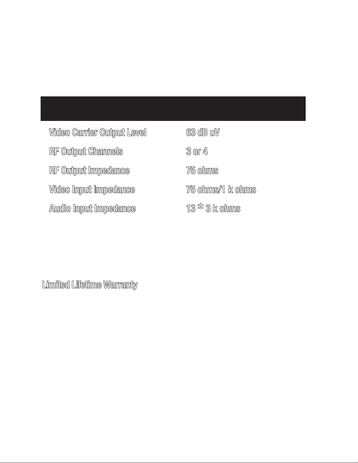
SPECIFICATIONS
Video Carrier Output Level 63 dB uV
RF Output Channels 3 or 4
RF Output Impedance 75 ohms
Video Input Impedance 75 ohms/1 k ohms
Audio Input Impedance 13 ±3 k ohms
Specifications are typical, individual units might vary. Specifications
are subject to change and improvement without notice.
Limited Lifetime Warranty
free from defects in material, workmanship and assembly, under normal use, in
accordance with the specifications and warnings, for the life of the product. This
warranty extends only to the original purchaser and is non-transferable. Defective
products must be returned with the dated proof of purchase to the place of
purchase for replacement. THERE ARE NO OTHER EXPRESS OR IMPLIED
WARRANTIES. Incidental or consequential damages are disclaimed where permitted
by law.
The Manufacturer warrants that this product shall be
Page 8

PRECAUCIÓN
PELIGRO DE ELECTROCHOQUE
NO ABRIR
PRECAUCIÓN:
SERVICIO A PERSONAL HABILITADO.
Modulador de RF para
Vídeo-Manual del Usuario
INTRODUCCIÓN
Este Modulador de RF para Vídeo está diseñado para convertir señales
separadas de audio y de vídeo (provenientes de una videocámara, computadora, videocasetera portátil, receptor satelital, reproductor de DVDs, etc.) en
señales de televisión VHF corrientes, para que Ud. las pueda ver en cualquier
televisor común.
Advertencia:
incendio o electrochoque,no exponga este producto a la lluvia o a la humedad.
para uso en interiores solamente; para reducir el riesgo de
Este símbolo tiene por objeto alertarle acerca de la
presencia de voltaje peligroso sin aislación en el interior
del Modulador de RF, de suficiente intensidad para representar peligro de electrochoque. No abra la caja del
Modulador de RF.
Este símbolo tiene por objeto informarle que la literatura
que acompaña a este Modulador de RF contiene importantes instrucciones de operación y mantenimiento.
Page 9

LA FCC QUIERE QUE UD. SEPA LO SIGUIENTE:
Este aparato está en conformidad con la Parte 15 de las normas de la
Comisión Federal de Comunicaciones (FCC Rules). Su funcionamiento está
sujeto a las siguientes condiciones: (1) este aparato no debe causar interferencia perjudicial, y (2) este aparato debe aceptar toda interferencia recibida,
incluso interferencia capaz de causar un funcionamiento no satisfactorio.
Aun en las mejores condiciones, el Modulador de RF para Vídeo podría causar
interferencia indeseable. Sugerimos las siguientes medidas para resolver el
problema:
1. Use un tomacorriente de corriente alterna conectado a un circuito distinto
al del receptor.
2. Coloque el Modulador de RF lo más lejos posible del receptor.
Si después que se hayan tomado estas medidas la interferencia persiste, las
reglamentaciones de la FCC exigen suspender el uso de este producto.
Información importante relativa a seguridad:
1. Antes de comenzar la instalación de su Modulador de RF de Vídeo,
lea todas las instrucciones y sígalas estrictamente durante la
instalación.
2. Después de completar la instalación, guarde todas las instrucciones en
un sitio seguro para poder consultarlas en el futuro en caso necesario.
3. Sírvase notar que el sitio ideal para este aparato es colocado sobre
una superficie dura, lejos de toda fuente de calor y de humedad.
Page 10

PIEZAS NECESARIAS
ANT IN
TO TV
LR
60Hz/4.5W
IN
S-VIDEO
VIDEO IN S-VIDEO IN
Salida de vídeo
O
Salida de s-vídeo
Fuente de vídeo
Para conectar el Modulador de RF de Vídeo entre una fuente de señales de
vídeo (juego de vídeo, videocámara, receptor satelital, reproductor de DVDs,
etc.) y su televisor, se necesitan los siguientes elementos, que no se suministran con el Modulador.
• Dos cables coaxiales de 75 ohms con conectores de tipo F
• Si su televisor no tiene un conector F de 75 ohms para VHF, también
necesitará un transformador de adaptación de 75 a 300 ohms
• Un cable blindado para vídeo con clavijas de conexión RCA y un cable
para audio (estereofónico) con clavijas de conexión RCA O Cable de
transposición para VCR/DVD con clavijas de conexión RCA O 3 cables
blindados con clavijas de conexión RCA
•Un Cable de S-Video
CONEXIONES
Para conectar su Modulador de RF siga los pasos siguientes:
1. Conecte un cable e s-vídeo o vídeo entre el receptáculo de salida de vídeo
de la fuente de señales de s-vídeo o vídeo empleada y el receptáculo rotulado
S-VIDEO INo VIDEO IN
Nota:
Si el S-Video y video uniforme se enganchan arriba,
el S-Video se dará la prioridad
del Modulador de RF.
a
n
i
h
C
2
0
1
2
7
#
Page 11

AUDIO IN
Salida de audio
audiofrecuencia
ANT IN
TO TV
LR
60Hz/4.5W
IN
S-VIDEO IN
A la TV
CATV/ANT
VHF
Modulador de RF VCR
ANT INT mhO 57VT O 75 Ohm
Desconectar
aquí
CONEXIONES (continuación)
2. Conecte el cable de audio entre el receptáculos de salida de audio de la
fuente de vídeo y el receptáculos rotulado
AUDIO IN
del Modulador de RF.
3. Conecte los cables coaxiales de 75 ohmios al modulador de RF eligiendo
una de las dos (2) opciones siguientes:
Opción 1: Si el televisor ya está conectado a otra fuente de entrada VHF (como
la televisión por cable, el vídeo, etc.):
a. Desconecte la conexión actual de la televisión por cable/antena del terminal
de entrada de 75 ohmios de la fuente VHF y vuelva a conectarla al terminal
ANT IN del modulador de RF.
Page 12

Ant In To TV 75 Ohm
Televisión
por cable
300 Ohms
VHF
Modulador de RF Televisor
CONNECTIONS continued
Televisión
por cable
Agregar este cable
Reconectar
aquí
Modulador de RF
VCR
VHF
ANT INTO TV
75 Ohm75 Ohm
OUTIN
Televisor
b. A continuación utilice un cable coaxial de 75 ohmios para conectar el
terminal TO TV del modulador de RF al terminal de entrada de 75 ohmios
de la fuente VHF.
Opcíon 2: Si su televisor no está ya conectado a otra fuente de señales VHF:
a. Desconecte el cable actual de la televisión por cable/antena del terminal
de entrada de 75 ohmios del televisor y vuelva a conectarlo al terminal
ANT IN del modulador de RF.
b. A continuación utilice un cable coaxial de 75 ohmios para conectar el
terminal TO TV del modulador de RF al terminal de entrada VHF de 75
ohmios del televisor.
Nota:
ohms, use un transformador de adaptación de 75 a 300 ohm para
Si su televisor tiene solamente terminales VHF de tornillo de 300
completar la conexión.
4. Enchufe el cable de alimentación del Modulador de RF en un tomacorriente común de corriente alterna.
Page 13

FUNCIONAMIENTO
4
3
MOD. ON
CHANNEL
1. Encienda el televisor y seleccione el Canal 3 ó 4 (elija el que no se use para
teledifusión en su zona).
2. Lleve la llave
CHANNEL 4/3
televisor (canal 3 ó 4).
de su Modulador de RF al mismo canal que el
3. Cuando se enciende la fuente de vídeo conectada al Modulador de RF, el
modulador transmite al televisor la señal de vídeo/audio y la luz indicadora
roja correspondiente a
MOD. ON
se ilumina.
4. Cuando se apaga la fuente de vídeo conectada al Modulador de RF, el
modulador pasa automáticamente a transmitir al televisor la señal
ANT/cable y la luz indicadora roja correspondiente a
MOD. ON
se apaga.
Page 14

ESPECIFICACIONES
Potencia de salida del canal de vídeo 63 dB uV
Canal de salida de RF 3 ó 4
Impedancia de salida de RF 75 ohms
Impedancia de entrada de vídeo 75 ohms/1 k ohms
Impedancia de entrada de audio 13 ±3 k ohms
Las especificaciones son generales; pueden haber diferencias entre unidades.
Las especificaciones pueden cambiar y mejorar sin previo aviso.
El fabricante garantiza que este producto no tendrá defectos de material, mano de
obra y ensamblaje, bajo uso normal, en conformidad con las especificaciones y
advertencias, durante la vida del producto. Esta garantía se extiende sólo al
comprador original y no es transferible. Los productos defectuosos deben devolverse con el comprobante de compra fechado al lugar de compra para obtener un
reemplazo. NO HAY NINGUNA OTRA GARANTÍA ESCRITA O IMPLÍCITA. Los daños
incidentales o emergentes se desconocen donde lo permita la ley.
Page 15

ATTENTION
RISQUE DE CHOC ÉLECTRIQUE.
ÉVITEZ D’OUVRIR.
ATTE NTION:
É
L’ENTRETIEN OU LES RÉPARATIONS À DU PERSONNEL QUALIFIÉ.
Modulateur HF vidéo-
Manuel du propriétaire
INTRODUCTION
Votre modulateur HF vidéo est conçu pour convertir les signaux audio et vidéo
séparés (provenant d’un caméscope, d’un ordinateur, d’un vidéoscope portatif,
d’un récepteur de satellite, d’un lecteur de vidéodisque, etc.) en signaux de
télévision VHF normaux que vous pouvez recevoir et regarder sur tout poste de
télévision ordinaire.
Avertissement:
amoindrir le risque d’incendie ou de choc électrique, évitez d’exposer cet
appareil aux intempéries ou à l’humidité excessive.
Cet appareil est destiné à usage à l’intérieur seulement; pour
Ce symbole a pour but de vous avertir de la présence
d’une tension dangereuse sans isolation dans le boîtier du
modulateur HF qui peut être de niveau assez élevé pour
présenter un risque de choc électrique. Évitez d’ouvrir le
boîtier du modulateur HF.
Ce symbole a pour but de vous informer que la documentation accompagnant ce modulateur HF contient d’importantes directives de fonctionnement et d’entretien.
Page 16

LE FCC VOUDRAIT QUE VOUS SACHIEZ
Ce dispositif se conforme à la partie 15 de la réglementation du FCC. Le
fonctionnement est soumis aux deux conditions suivantes : (1) Ce dispositif ne
doit pas produire de perturbations ou de brouillage nuisibles; (2) il doit absolument accepter tout brouillage ou perturbation reçus, y compris le brouillage
ou les perturbations pouvant altérer son fonctionnement.
Même dans des conditions de fonctionnement optimales,votre modulateur HF
vidéo pourra causer du brouillage ou des perturbations indésirables. Nous
suggérons les méthodes suivantes de repérage de pannes:
1. Utilisez une prise c.a. qui ne fonctionne pas sur le même circuit que
le récepteur.
2. Placez le modulateur HF à un endroit éloigné de votre récepteur.
Advenant du brouillage ou des perturbations même à la suite de l’adoption des
mesures ci-dessus, la réglementation du FCC vous exige d’abandonner l’utilisation de ce produit.
Renseignements importants concernant la sécurité.
1. Avant d’amorcer la mise en place de votre modulateur HF vidéo, lisez
toutes les directives et suivez-les à la lettre tout le long de la mise en
place.
2. Une fois la mise en place achevée, conservez toutes les directives dans
un endroit sûr où vous pourrez les reconsulter ultérieurement au besoin.
3. Veuillez noter qu’une surface plane dure éloignée de toute source de
chaleur et(ou) d’humidité constitue l’environnement idéal pour ce
dispositif.
Page 17

PIÈCES REQUISES
ANT IN
TO TV
LR
60Hz/4.5W
IN
S-VIDEO
S-VIDEO INVIDEO IN
Sortie s-vidéoSortie vidéo
OU
Source vidéo
Il vous faut les articles suivants, non fournis avec votre modulateur HF vidéo,
pour le relier entre une source d’entrée vidéo (jeu vidéo, caméscope,récepteur
de satellite, lecteur de vidéodisque, etc.) et votre poste de télévision.
• deux câbles coaxiaux 75-ohm avec connecteurs du type F
• un transformateur correspondant 75 ohm-à-300 ohm, si votre
poste de télévision ne dispose pas d’un connecteur 75-ohm VHF
du type F
• un câble blindé vidéo avec fiches RCA et un câble audio (stéréo) avec
fiches RCA OU câble de raccordement magnéstocope / lecteur de DVD
avec fiches RCA OU 3 câbles blindés avec fiches RCA
•un câble S-VIDEO
CONNEXIONS
Suivez les étapes ci-dessous afin de relier votre modulateur HF:
1. Raccordez un câble s-vidéo ou vidéo entre la prise de sortie s-vidéo ou vidéo
de votre source vidéo et la prise
S-VIDEO
VIDEO IN
ou
du modulateur HF.
Note:
Si le S-VIDEO et le vidéo standard sont relié, le S-VIDEO sera donné
la priorité
Page 18
Prises AUDIO IN
Sortie audio
Source audio
ANT IN
TO TV
LR
60Hz/4.5W
IN
S-VIDEO
Câblodistributeur
Modulateur HF
VHF
Déconnecter
à partir d’ici
VCR
ANT INTO TV
75 Ohm75 Ohm
télévision
CONNEXIONS (suite)
2. Raccordez un câble audio entre la prises de sortie audio de votre source
vidéo et la prises
AUDIO IN
du modulateur HF.
3. Connectez les câbles coaxiaux de 75
deux façons suivantes :
ohms au modulateur RF de l'une des
Option 1 :Si votre téléviseur est déjà connecté à une autre source d’entrée VHF
(telles que la télévision par câble, un magnétoscope, etc.) :
a. Débranchez votre connexion (antenne ou câblodistribution) de votre
terminal d’entrée VHF à 75 ohms, puis branchez-la au terminal ANT IN du
modulateur RF.
Page 19

Ant In To TV 75 Ohm
Câblodistributeur
300 Ohms
VHF
Modulateur HF Poste de télévision
CONNEXIONS (suite)
Câblodistributeur
A
joutez ce câble
Reconnectez ici
Modulateur HF
VCR
VHF
A
NT INTO TV
75 Ohm75 Ohm
OUTIN
Télévision
b Connectez ensuite le terminal TO TV du modulateur RF à votre source
d’entrée VHF par un câble coaxial de 75 ohms.
Option2:Si votre poste de télévision n’est pas déjà relié à une autre source
d’entrée VHF:
a. Débranchez votre câble (antenne ou câblodistribution) de votre terminal
d’entrée TV à 75 ohms, puis branchez-la au terminal ANT IN du
modulateur RF.
b. Connectez ensuite le terminal TO TV du modulateur RF à votre téléviseur
par un câble coaxial de 75 ohms.
Nota:
Si votre poste de télévision dispose uniquement de bornes VHF à
vis 300-ohm, employez un transformateur correspondant 75 ohm-à-300
ohm pour compléter la connexion.
4. Enfichez le cordon d’alimentation du modulateur HF dans une prise c.a.
ordinaire.
Page 20

FONCTIONNEMENT
4
3
MOD. ON
CHANNEL
1. Mettez le poste de télévision sous tension et sélectionnez le canal 3 ou 4,
selon celui qui ne sert pas aux télédiffusions régulières dans votre région.
2. Réglez le commutateur
CHANNEL 4/3
sur le poste de télévision (3 ou 4).
au même canal que vous avez réglé
3. Mettre la source vidéo sous tension; le modulateur émet alors ses signaux
audio/vidéo au téléviseur (le témoin à DEL rouge «
MOD. ON
» s’allume).
4. Mettre la source vidéo sous tension; le modulateur se commute alors
automatiquement pour transmettre ses signaux de
câblodiffusion/d’antenne au téléviseur (le témoin à DEL rouge
MOD. ON
«
» s’éteint).
Page 21

FICHE TECHNIQUE
Niveau de sortie de la porteuse vidéo 63 dB uV
Canaux de sortie HF 3 ou 4
Impédance de sortie HF 75 ohms
Impédance d’entrée vidéo 75 ohms/1 k ohms
Impédance d’entrée audio 13 ±3 k ohms
Les valeurs sont types; les unités individuelles pourront varier. La
fiche technique est susceptible de modifications et(ou) d’améliorations
s
ans préavis.
GARANTIE à vie limitée
matériaux, de fabrication ou d’assemblage, lorsqu’il est utilisé normalement,
conformément aux spécifications et avertissements, pendant la durée du produit.
Cette garantie non transférable est offerte à l’acheteur initial seulement. Les
produits défectueux doivent être retournés, accompagnés d’une preuve d’achat
datée, à l’endroit où ils ont été achetés en vue d’être remplacés. IL N’EXISTE
AUCUNE AUTRE GARANTIE EXPRESSE OU IMPLICITE. Le fabricant décline toute
responsabilité quant aux dommages consécutifs ou indirects lorsque la loi
l’autorise.
Le fabricant garantit ce produit contre tout défaut de
 Loading...