

Philips TZA1027HL-V2 Datasheet
DATA SH EET
Preliminary specification
File under Integrated Circuits, IC01
1999 Sep 17
INTEGRATED CIRCUITS
TZA1027
Analog current buffer for CD-R and
CD-RW systems
1999 Sep 17 2
Philips Semiconductors Preliminary specification
Analog current buffer for CD-R and CD-RW
systems
TZA1027
FEATURES
• Eight amplifiers for servo and power calibration
functions
• Gain selector for CD-R and CD-RW discs
• Separate dataamplifier for read speed up to thirty times
nominal data speed.
GENERAL DESCRIPTION
The TZA1027 is an analog current buffer IC for CD-R and
CD-RW systems with a 3-spot push-pull tracking system.
The IC interfaces directly to the photo diodes and
TZA1020. A HF current amplifier is implemented to detect
the actual HF data signal.
QUICK REFERENCE DATA
ORDERING INFORMATION
SYMBOL PARAMETER CONDITIONS MIN. TYP. MAX. UNIT
V
DD
supply voltage 4.5 5.0 5.5 V
I
i(cd)
central diode input current WRON = 1 0 − 3400 µA
I
i(sd)
satellite diode input current WRON = 1 0 − 520 µA
B
CAHF
bandwidth Ci= 5 pF 72 −−MHz
t
d(f)
flatness delay Ci= 5 pF; f = 0.1 to 32 MHz − 30 200 ps
G
SS
servo satellite detector gain HG = 1 − 32 −
HG=0 − 8 −
T
amb
ambient temperature 0 − 70 °C
TYPE
NUMBER
PACKAGE
NAME DESCRIPTION VERSION
TZA1027HL LQFP32 plastic low profile quad flat package; 32 leads; body 5 × 5 × 1.4 mm SOT401-1
1999 Sep 17 3
Philips Semiconductors Preliminary specification
Analog current bufferforCD-R and CD-RW
systems
TZA1027
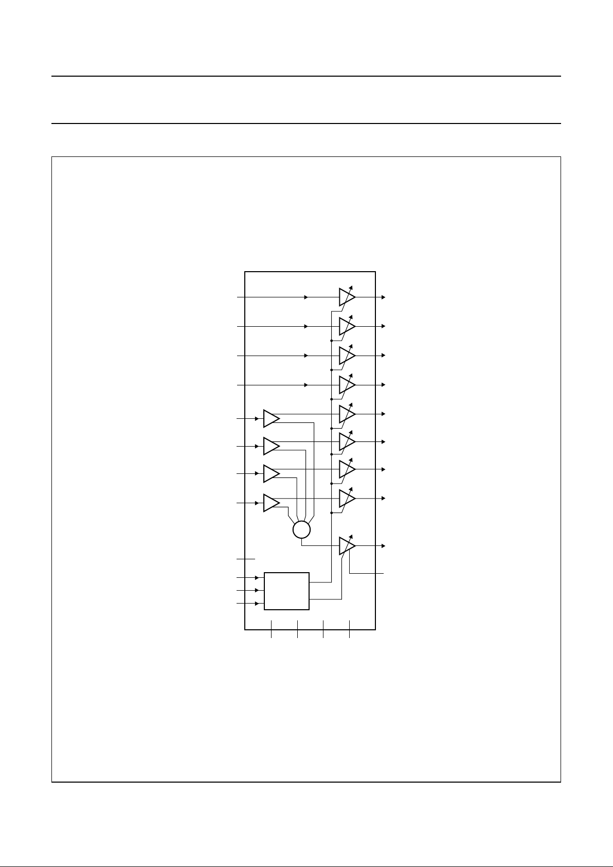
BLOCK DIAGRAM
Fig.1 Block diagram.
MGR881
handbook, full pagewidth
TZA1027
237
282
246
273
29
1
22
8
25
5
26
CAHF
C4LF
19
HFGND
18
4
C4
C3
C3LF
C2
C2LF
C1
C1LF
B2
B2LF
B1
B1LF
A2
A2LF
A1
A1LF
9, 10, 11, 12,
17, 20, 32
21
PDWN
31
WRON
30
HG
16
n.c.
+
15 13 14
AGND
V
DDD
V
DDA
GAIN
SELECTOR
DGND

1999 Sep 17 4
Philips Semiconductors Preliminary specification
Analog current bufferforCD-R and CD-RW
systems
TZA1027
PINNING
SYMBOL PIN DESCRIPTION
C1 1 central photo diode current input
A2 2 satellite diode current input
B2 3 satellite diode current input
C4 4 central photo diode current input
C3 5 central photo diode current input
B1 6 satellite diode current input
A1 7 satellite diode current input
C2 8 central photo diode current input
n.c. 9 not connected
n.c. 10 not connected
n.c. 11 not connected
n.c. 12 not connected
AGND 13 analog ground
DGND 14 digital ground
V
DDD
15 digital power supply
V
DDA
16 analog power supply
n.c. 17 not connected
HFGND 18 ground connection of CAHF output stage
CAHF 19 central aperture high-frequency output
n.c. 20 not connected
PDWN 21 digital input power-down
C2LF 22 C2 central detector signal output
A1LF 23 A1 satellite detector signal output
B1LF 24 B1 satellite detector signal output
C3LF 25 C3 central detector signal output
C4LF 26 C4 central detector signal output
B2LF 27 B2 satellite detector signal output
A2LF 28 A2 satellite detector signal output
C1LF 29 C1 central detector signal output
HG 30 digital input high gain selection
WRON 31 digital input write on gain selection
n.c. 32 not connected
1999 Sep 17 5
Philips Semiconductors Preliminary specification
Analog current bufferforCD-R and CD-RW
systems
TZA1027
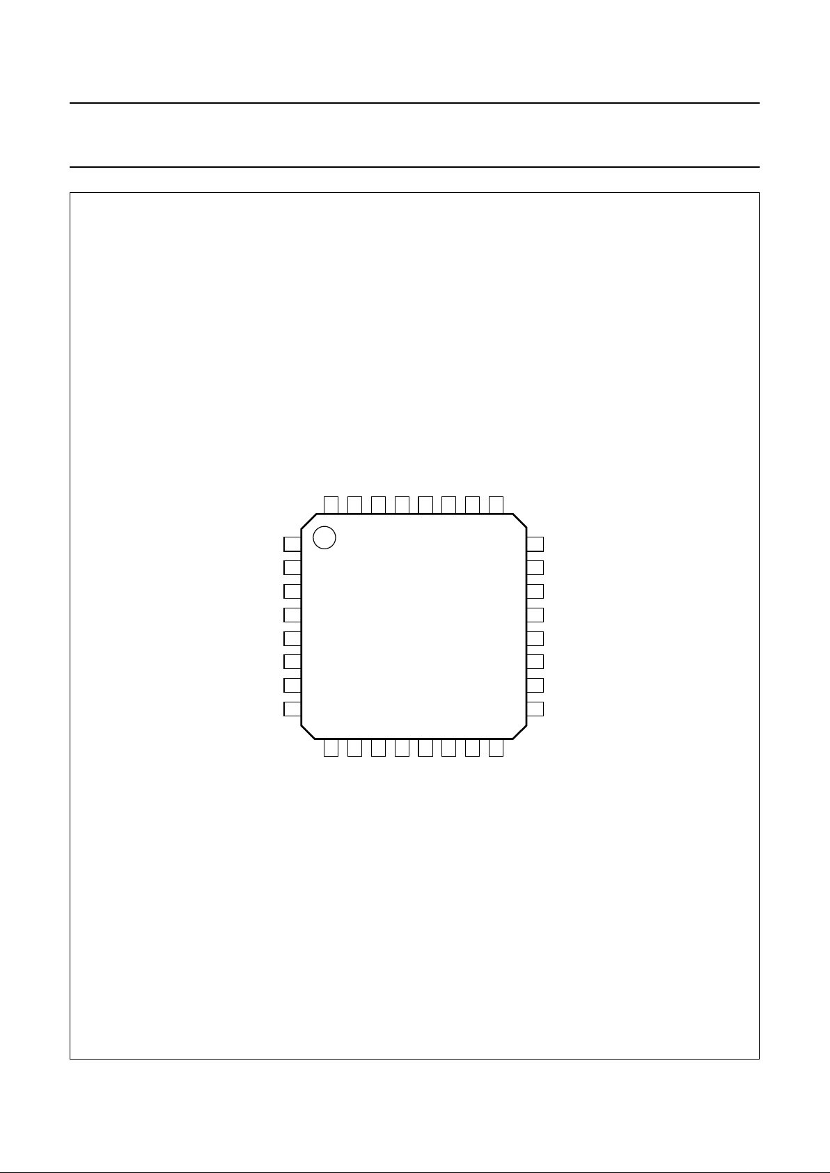
handbook, full pagewidth
TZA1027HL
MGR882
1
2
3
4
5
6
7
8
24
23
22
21
20
19
18
17
9
10
11
12
13
14
15
16
32
31
30
29
28
27
26
25
C1
C3
C2
A1
B2
B1
n.c.
n.c.
AGND
n.c.
V
DDD
C4LF
A2LF
n.c.
C1LF
C2LF
n.c.
B2LF
A1LF
n.c.
HFGND
PDWN
WRON
HG
V
DDA
C3LF
B1LF
CAHF
DGND
n.c.
C4
A2
Fig.2 Pin configuration.
 Loading...