

Page 1

5. Service Modes, Error Codes, and Fault Finding
Index of this chapter:
5.1 Test Points
5.2 Service Modes
5.3 Stepwise Start-up
5.4 Service Tools
5.5 Software Upgrading
5.6 Error Codes
5.7 The Blinking LED Procedure
5.8 Fault Finding and Repair Tips
5.1 Test Points
As most signals are digital, it will be difficult to measure
waveforms with a standard oscilloscope. However, several key
ICs are capable of generating test patterns, which can be
controlled via ComPair. In this way it is possible to determine
which part is defective.
Perform measurements under the following conditions:
• Service Default Mode.
• Video: Colour bar signal.
• Audio: 3 kHz left, 1 kHz right.
5.2 Service Modes
The Service Mode feature is split into five parts:
• Service Default Mode (SDM).
• Service Alignment Mode (SAM).
• Factory Mode.
• Customer Service Mode (CSM).
• Computer Aided Repair Mode (ComPair).
Life Timer
During the life time cycle of the TV set, a timer is kept (called
“Op. Hour”). It counts the normal operation hours (not the
Stand-by hours). The actual value of the timer is displayed in
SDM and SAM in a decimal value. Every two soft-resets
increase the hour by + 1. Stand-by hours are not counted.
Software Identification, Version, and Cluster
The software ID, version, and cluster will be shown in the main
menu display of SDM, SAM, and CSM.
The screen will show: “AAAAB-X.YYY”, where:
• AAAA is the chassis name: T913E x.yyy.
• B is the region indication: E = Europe, A = AP/China, U =
NAFTA, L = LATAM.
• X is the main version number: this is updated with a major
change of specification (incompatible with the previous
software version). Numbering will go from 1 - 99 and
AA - ZZ.
- If the main version number changes, the new version
number is written in the NVM.
- If the main version number changes, the default settings
are loaded.
• YYY is the sub version number: this is updated with a minor
change (backwards compatible with the previous
versions). Numbering will go from 000 - 999.
- If the sub version number changes, the new version
number is written in the NVM.
- If the NVM is refreshed, the software identification,
version, and cluster will also be written to NVM.
5.
SDM, SAM and the Factory mode offer features, which can be
used by the Service engineer to repair/align a TV set. Some
features are:
• A pre-defined situation to ensure measurements can be
made under uniform conditions (SDM).
• Activates the blinking LED procedure for error identification
when no picture is available (SDM).
• Make alignments (e.g. White Tone), reset the error buffer
(SAM and Factory Mode).
• Display information (“SDM” or “SAM” indication in upper
right corner of screen, error buffer, software version,
operating hours, options and option codes, sub menus).
The CSM is a Service Mode that can be enabled by the
consumer. The CSM displays diagnosis information, which the
customer can forward to the dealer or call centre. In CSM
mode, “CSM”, is displayed in the top right corner of the screen.
The information provided in CSM and the purpose of CSM is to:
• Increase the home repair hit rate.
• Decrease the number of nuisance calls.
• Solved customers’ problem without home visit.
ComPair Mode is used for communication between a computer
and a TV on I
engineer to quickly diagnose the TV set by reading out error
codes, read and write in NVMs, communicate with ICs and the
mP (PWM, registers, etc.), and by making use of a fault finding
database. It will also be possible to up and download the
software of the TV set via I
ComPair has to be connected to the TV set via the ComPair
connector, which will be accessible through the rear of the set
(without removing the rear cover).
Note: For the new model range, a new remote control (RC) is
used with some renamed buttons. This has an impact on the
activation of the Service modes. For instance the old “MENU”
button is now called “HOME” (or is indicated by a “house” icon).
5.2.1 General
Next items are applicable to all Service Modes or are general.
2
C /UART level and can be used by a Service
2
C with help of ComPair. To do this,
Display Option Code Selection
When after an SSB or display exchange, the display option
code is not set properly, it will result in a TV with “no display”.
Therefore, it is required to set this display option code after
such a repair.
To do so, press the following key sequence on a standard RC
transmitter: “062598” directly followed by MENU and “xxx”,
where “xxx” is a 3 digit decimal value of the panel type: see
column “Display Code” in Table 6-3
accepted and stored in NVM, the set will switch to Stand-by, to
indicate that the process has been completed.
During this algorithm, the NVM-content must be filtered,
because several items in the NVM are TV-related and not SSB
related (e.g. Model and Prod. S/N). Therefore, “Model”
and “Prod. S/N” data is changed into “See Type Plate”. In case
a call centre or consumer reads “See Type Plate” in CSM
mode.
5.2.2 Service Default Mode (SDM)
Purpose
Set the TV in SDM mode in order to be able to create a
predefined setting for measurements to be made. In this
platform, a simplified SDM is introduced (without protection
override and without tuning to a predefined frequency).
Specifications
• Set linear video and audio settings to 50%, but volume to
25%. Stored user settings are not affected.
• All service-unfriendly modes (if present) are disabled, since
they interfere with diagnosing/repairing a set. These
service unfriendly modes are:
– (Sleep) timer.
– Blue mute/Wall paper.
– Auto switch “off” (when there is no “ident” signal).
– Hotel or hospital mode.
– Child lock or parental lock (manual or via V-chip).
– Skipping, blanking of “Not favourite”, “Skipped” or
“Locked” presets/channels.
– Automatic storing of Personal Preset or Last Status
settings.
. When the value is
Page 2
– Automatic user menu time-out (menu switches
back/OFF automatically.
– Auto Volume levelling (AVL).
How to Activate SDM
To activate SDM, use the following methods:
• Press the following key sequence on the RC transmitter:
“062596”, directly followed by the “Home” button.
After activating this mode, “SDM” will appear in the upper left
corner of the screen.
On Screen Menu
After activating SDM, the following items are displayed, with
SDM in the upper right corner of the screen to indicate that the
television is in Service Default Mode. Menu items and
explanation:
• xxxxx Operating hours (in decimal).
• AAAAB-X.YYY See Software Identification, Version, and
Cluster for the software name definition.
• ERR Shows all errors detected since the last time the
buffer was erased in format <xxx> <xxx> <xxx> <xxx>
<xxx> (five errors possible).
• OP Used to read-out the option bytes. In this chassis two
times eight option codes are used.
How to Navigate
As this mode is read only, there is nothing to navigate. To
switch to other modes, use one of the following methods:
• Command MENU from the user remote will exit SDM.
• To prevent the OSD from interfering with measurements in
SDM, use the command “Adjust” or “Options” (“STATUS”
or “INFO” for NAFTA and LATAM) from the user remote.
This will switch the OSD “off” while remaining in the SDM
mode. The “SDM” OSD is remains visible in the upper right
coner of the screen. To exit SDM switch to “Stand-by”
mode.
• Press the following key sequence on the remote control
transmitter: “062596” directly followed by the OK button to
switch to SAM (do not allow the display to time out between
entries while keying the sequence). Remarks: new remote
controls will not have I+ button, but an “INFO” button
instead.
How to Exit SDM
• Switch the set to Stand-by by pressing the standby button
on the remote control transmitter or on the television set.
• Via a standard customer RC-transmitter: key
in “00”-sequence.
Note: If the TV is switched “off” by a power interrupt while
in SDM, the TV will show up in the last status of SDM menu
as soon as the power is supplied again. The error buffer will
not be cleared.
5.2.3 Service Alignment Mode (SAM)
Purpose
• To modify the NVM.
• To display/clear the error code buffer.
• To perform alignments.
Specifications
• Operation hours counter (maximum five digits displayed).
• Software version, error codes, and option settings display.
• Error buffer clearing.
• Option settings.
• Software alignments (White Tone).
• NVM Editor.
• Set screen mode to full screen (all content is visible).
How to Activate SAM
To activate SAM, use one of the following methods:
• Press the following key sequence on the remote control
transmitter: “062596”, directly followed by the “INFO”
button. Do not allow the display to time out between entries
while keying the sequence.
• Or via ComPair.
After entering SAM, the following items are displayed,
with “SAM” in the upper right corner of the screen to indicate
that the television is in Service Alignment Mode.
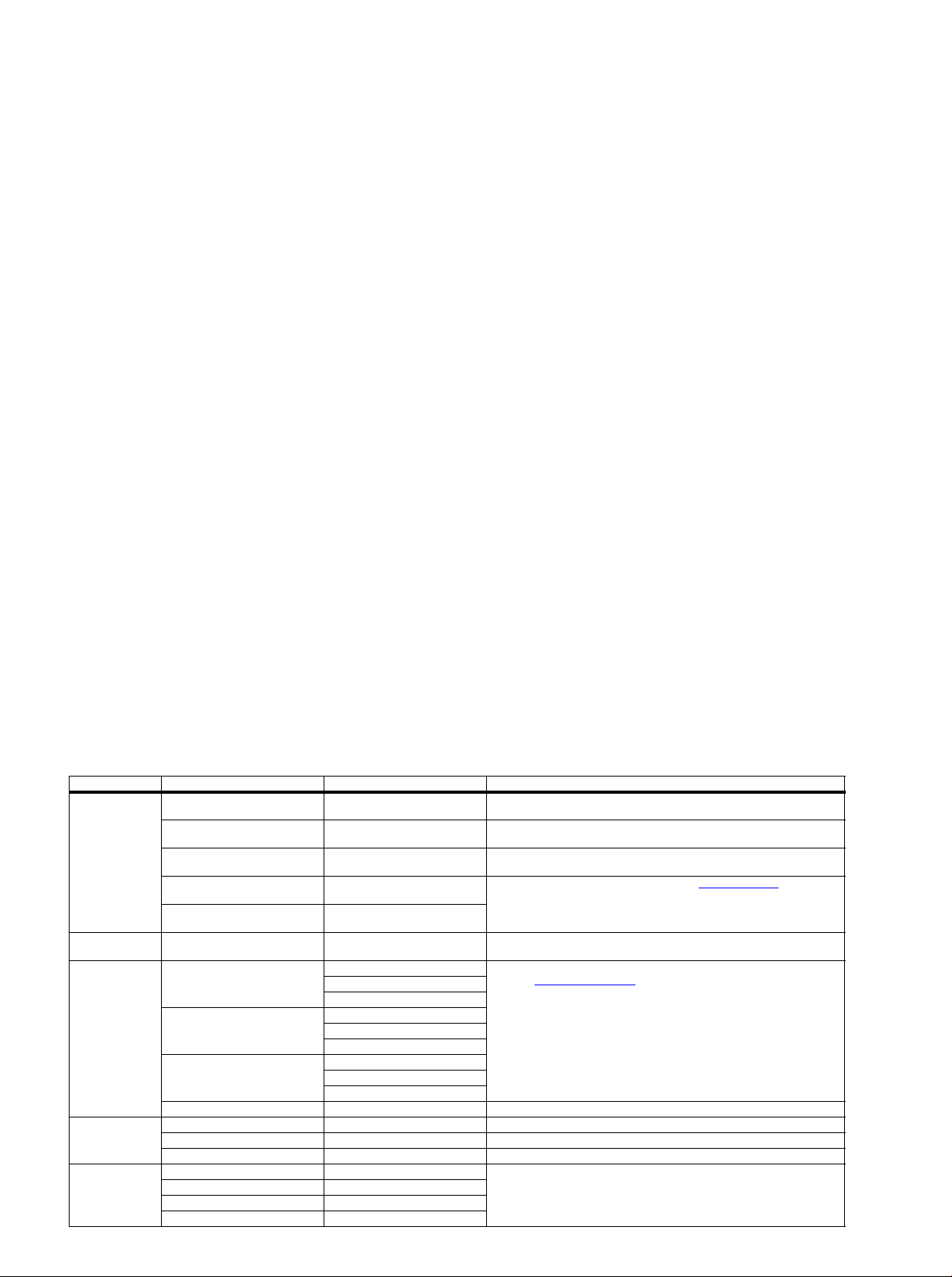
Table 5-1 SAM mode overview
Main Menu Sub-menu 1 Sub-menu 2 Description
System Information Op Hour This represents the life timer. The timer counts normal operation hours, but does not
Main SW ID e.g. “TPM913E 1.055A” See paragraph Software Identification, Version, and Cluster for the software name
ERR e.g. “000 000 000 000 000” Shows all errors detected since the last time the buffer was erased. Five errors
OP1 e.g. “012 007 208 002 184 032 007
OP2 e.g. “056 023 000 106 064 000 000
Clear Press [OK] to clean the Error Codes
RGB Align Warm R Gain To align the White Tone. See
NVM editor Address Select and fill the NVM address
Upload to USB Copy Channel List to USB To upload several settings from the TV to an USB stick
immediately
Normal R Gain
Cool R Gain
Store Store the RGB value
Value Select and fill the NVM value
Store Store the value in the address
Copy NVM to USB
Copy Readable Info to USB
Copy EDID to USB
030”
122”
G Gain
B Gain
G Gain
B Gain
G Gain
B Gain
count Stand-by hours.
definition.
possible.
Used to read-out the option bytes. See paragraph 6.4 Option Settings
Alignments section for a detailed description. Ten codes are possible.
Erases the contents of the error buffer. Select this menu item and press the MENU
RIGHT key on the remote control. The content of the error buffer is cleared.
paragraph 6.3 Software Alignments
in the Alignments section for a detailed description
in the
Page 3
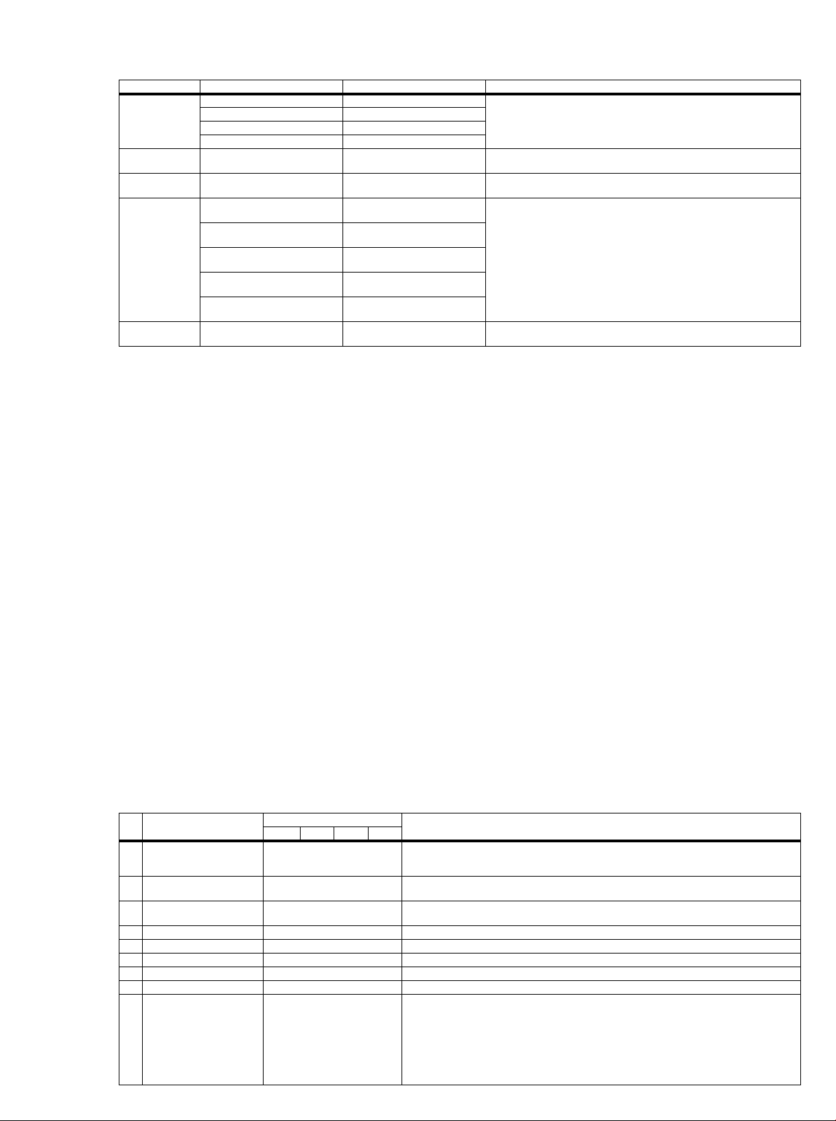
Main Menu Sub-menu 1 Sub-menu 2 Description
Download from USB Copy Channel List from USB To download several settings from the USB stick to the TV
Initialize NVM Press [OK] to Initialize NVM
EDID Write Enable Press [OK] to enable EDID writable
Service Data Type Number Press [OK] use key pad edit type
Clear OAD Version Press [OK] to clean OAD Version
Copy NVM from USB
Copy Readable Info from USB
Copy EDID from USB
immediately
immediately
number immediately
Production Number Press [OK] use key pad edit
production number immediately
12NC SSB Press [OK] use key pad edit SSB
immediately
12NC PSU Press [OK] use key pad edit PSU
immediately
12NC Display Press [OK] use key pad edit display
immediately
immediately
To initialize a (corrupted) NVM. Be careful, this will erase all settings.
Enable EDID for writing
Edit and display the applicable service data by using the displayed key pad.
Clean OAD (Over Air Download, firmware update method) Version
How to Navigate
• In the SAM menu, select menu items with the UP/DOWN
keys on the remote control transmitter. The selected item
will be indicated. When not all menu items fit on the screen,
use the UP/DOWN keys to display the next/previous menu
items.
• With the “LEFT/RIGHT” keys, it is possible to:
– (De) activate the selected menu item.
– (De) activate the selected sub menu.
– Change the value of the selected menu item.
• When you press the MENU button once while in top level
SAM, the set will switch to the normal user menu (with the
SAM mode still active in the background).
• Press the following key sequence on the remote control
transmitter: “062596” directly followed by the “Home”
button to switch to SDM (do not allow the display to time out
between entries while keying the sequence).
How to Store SAM Settings
To store the settings changed in SAM mode (except the
RGB Align settings), leave the top level SAM menu by using
the POWER button on the remote control transmitter or the
television set. The mentioned exceptions must be stored
separately via the STORE button.
How to Exit SAM
Use one of the following methods:
• Switch the set to STANDBY by pressing the mains button
on the remote control transmitter or the television set.
• Via a standard RC-transmitter, key in “00” sequence.
Note: When the TV is switched “off” by a power interrupt while
in SAM, the TV will show up in “normal operation mode” as
soon as the power is supplied again. The error buffer will not be
cleared.
5.2.4 Contents of the Factory mode:
Purpose
• To perform extended alignments.
Specifications
• Displaying and or changing Panel ID information.
• Displaying and or changing Tuner ID information.
• Error buffer clearing.
• Various software alignment settings.
• Testpattern diplaying.
• Public Broadcasting Service password Reset.
•etc.
How to Activate the Factory mode
To activate the Factory mode, use the following method:
• Press the following key sequence on the remote control
transmitter: from the “Home screen” press “1999”, directly
followed by the “Back” button. Do not allow the display to
time out between entries while keying the sequence.
After entering the Factory mode, the following items are
displayed,
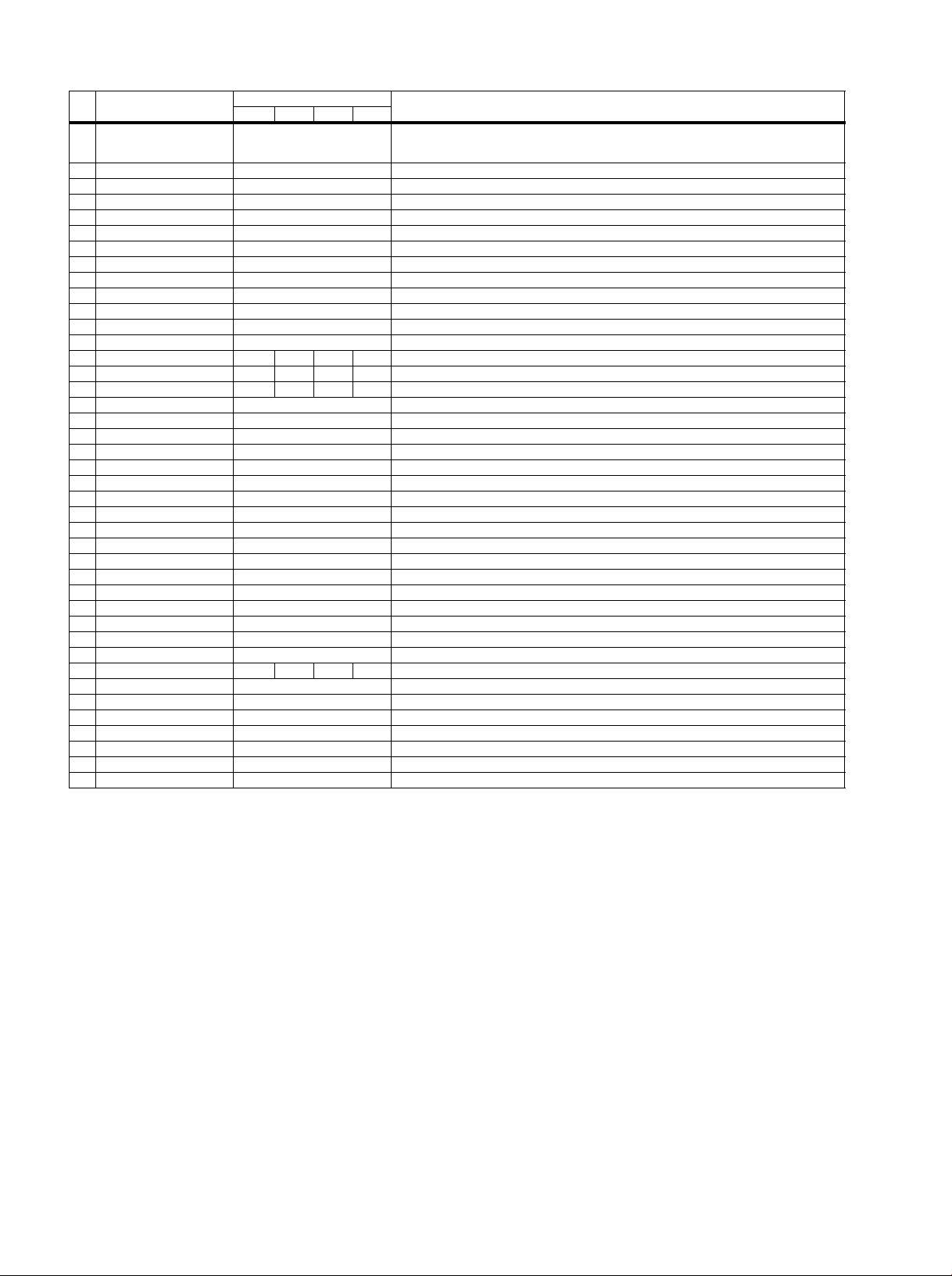
Table 5-2 Factory mode overview
Default value
Item Itemvakue
0 F/W VERSION Press OK Displays the software versions of the supplier, Flash PQ, Smart Picture, BL Dimming, Source Meter, the
1 Panel_ID See table 6-3 Display code overview Displays and changes the Panel ID wit h th e le ft a nd r ig ht cur sor ; b e car efu l cha ng ing this, it can result in not
2 Tuner ID 105: LG TDTK-G731D
3 ERR Code: xxx xxx xxx xxx xxx 000 000 000 000 000 Values showing the last 5 errors during the last 50 hrs of operation, according to table 5-4 Error code table
4 CLEAR ERROR BUFFER Press OK Selecting this clear all current erro r codes.
5 NVM ADDRESS 0 NVM address 0 to 8191, Use Item 6 to change and 7 to store the data to the correct NVM address
6 NVM VALUE various Displays the value at the NVM address of item 5
7 NVM STORE Press OK Use this option to save the data of item 6 to NVM address of item 5
8 NVM COPY TV to USB Press OK Use this to store the NVM data to the REPAIR folder of a FAT formatted USB memory stick. The TV will write
161: Panasonic ENV57U09D5F
Description32" 37" 42" 47"
Picture Quality checksum, the Dimming library, the Source meter library, the Flash AQ, the MTK, MCU and
OAD software versions.
correct displaying the screen!
Displays and changes the Tuner ID w ith the left and righ t cursor. Not to be cha nged when the tuner i s replaced
with the correct service part
two files in the REPAIR folder of the memory stick. It will create this folder if it does not exist. The items are
“Channel list”, “Personal settings”, “ Option codes”, “D isplay-r elated al ignments” a nd “Histo ry list”. In case the
download to the USB stick was not successful “Failure” will appear. In this case, check if the USB stick is
connected properly. Now the settings are stored onto the USB stick and can be used to download onto
another TV or other SSB. Uploading is of course only possible if the software is running and if a picture is
available. This method is create d to be able to save the custom er’s TV setting s and to store th em into anoth er
SSB.
Page 4
Default value
Item Itemvakue
9 NVM COPY USB to TV Press OK Use this to store the NVM data from the USB memory stick to the TV. The TV will save the two files which
10 RESET_PBS_PWD Press OK Use this to reset the Child Lock
11 DIM_LIB_RESET Press OK Reset the Dimming
12 SRC_METER RESET Press OK Reset the Source meter
13 CIPLUS_QUERY Press OK Shows the Validity of the CI+ key and the supplier information
14 CIPLUS UPDATE Press OK Used to enter a new CI+ code into the NVM. This can only be used when no CI+ code exists in the NVM
15 EDID UPDATE Press OK Used to enter a new EDID codes into the NVM
16 Test Pattern Press OK With the “left” and “right” keys of the remote control various test patterns can be chosen
17 VIRGIN_MODE Off/On Use this to return the set to virgin mode. Depends whether the set has been used already.
18 E-Fuse On E-fuse mode
18 ORT_MODE Off ORT mode
20 VGA_UART_SWITCH Off When switched “on” the VGA port can be used for UART logging.
21 AGEING MODE Off Use this for ageing a new LCD panel
22 CLR_TEMP_R 128 Red colour temperature setting
23 CLR_TEMP_G 128 Green colour temperature setting
24 CLR_TEMP_B 128 Red colour temperature setting
25 AUTO_COLOR Press OK PC: any pattern that has blac k and white, YPbPr: SMPTE bar (colour bar), any timing.
26 ADC_GAIN_R 164 Red ADC gain
27 ADC_GAIN_G 164 Green ADC gain
28 ADC_GAIN_B 164 Blue ADC gain
29 ADC_OFFSET_R 164 Red ADC offset
30 ADC_OFFSET_G 164 Green ADC offset
31 ADC_OFFSET_B 164 Blue ADC offset
32 YPBPR_PHASE InValid Not available for this chassis
33 AUD_LIMITER_MODE 2 Three modes, 0: off, 1: adaptive mode, 2: fixed mode
34 AUD_THRESHOLD_BYTE1 32 Limit threshold
35 AUD_THRESHOLD_BYTE2 32 Limit threshold
36 AUD_THRESHOLD_BYTE3 5 Limit threshold
37 AUD_GAIN_LINEIN 3 Line-in audio gain
38 AUD_GAIN_HDMI 2 HDMI audio gain
39 AUD_GAIN_ATV 3 Analogue TV audio gain
40 AUD_GAIN_DTV 2 Digital TV audio gain
41 AUD_GAIN_USB 2 USB audio gain
42 AQ_INDEX 0 1 2 3 Audio Quality index
43 Audio Test Mode Off Used for audio testing during production
44 Audio Channel Type 2.0 Defines the installed speaker system
45 DUMP PQ FROM TV Press OK Saves the picture quality data to a file “pq.bin” to the root of a FAT formatted USB memory stick
46 LOAD PQ to TV Press OK Loads the picture quality data from a file “pq.bin” in to the TV
47 DUMP AQ FROM TV Press OK Saves the audio quality data to a file “AQ.bin” to the root of a FAT formatted USB memory stick
48 LOAD AQ to TV Press OK Loads the audio quality data from a file “AQ.bin” in to the TV
49 EXIT_FACTORY Press OK Exits the Factory mode
Description32" 37" 42" 47"
were created in item 8 to the NVM of the set. Use these options when replacing a SSB. When “USB to TV
Success” is displayed remove the power and restart the TV
How to Exit the Factory mode
Use one of the following methods:
• Select EXIT_FACTORY from the menu and press the “OK”
button.
Note: When the TV is switched “off” by a power interrupt, or
normal switch to “stand-by” while in the factory mode, the TV
will show up in “normal operation mode” as soon as the power
is supplied again. The error buffer will not be cleared.
5.2.5 Customer Service Mode (CSM)
Purpose
The Customer Service Mode shows error codes and
information on the TV’s operation settings.The call centre can
instruct the customer (by telephone) to enter CSM in order to
identify the status of the set.This helps the call centre to
diagnose problems and failures in the TV set before making a
service call.
The CSM is a read-only mode; therefore, modifications are not
possible in this mode.
Specifications
• Ignore “Service unfriendly modes”.
• Line number for every
line (to make CSM language independent).
• Set the screen mode to full
screen (all contents on screen is visible).
• After leaving the Customer Service Mode, the original
settings are restored.
• Possibility to use “CH+” or “CH-” for channel surfing, or
enter the specific channel number on the RC.
How to Activate CSM
To activate CSM, press the following key sequence on a
standard remote control transmitter: “123654” (do not allow the
display to time out between entries while keying the sequence).
After entering the Customer Service Mode, the following items
are displayed.
Note: Activation of the CSM is only possible if there is no (user)
menu on the screen!
Contents of CSM
• 1.1 Set Type This information is very helpful for a
helpdesk/workshop as reference for further diagnosis. In
this way, it is not necessary for the customer to look at the
rear of the TV-set. Note that if an NVM is replaced or is
initialized after corruption, this set type has to be re-written
to NVM.
• 1.2 Production code Displays the production
code (the serial number) of the TV. Note that if an NVM is
replaced or is initialized after corruption, this production
code has to be re-written to NVM.
Page 5
• 1.3 Installation date Indicates the date of the first
19080_206_110323.eps
120224
Power Off
Standby
Soft Mode
Power On
Semi-
Standby
Standby
Switch
Off(Mains
Power Plug)
Standby Soft Mode
Command Received,
previously in Standby
Soft Mode (Power tact
switch)
TV Wakeup
commands
Received
(TV Wakeup
keys)
Digital
background
tasks started
Digital
background
tasks completed
Swith On,
previously in
Standby/Semi-
Standby (Mains
Power Plug)
Standby
Soft Mode
Command
Received
(Power tact
switch)
Switch Off (Mains
Power Plug)
Switch Off
(Mains Power
Plug)
Swith On,
previously in
Standby Soft Mode
(Mains Power Plug)
Standby
commands
Received (RC
Standby key)
Standby Soft Mode
Command Received,
previously in Standby
Soft Mode (Power
tact switch)
TV Wakeup
commands
Received
(TV Wakeup
keys)
Switch On, previously
in Power On Mode
(Power tact switch)
Standby Soft Mode
Command Received,
(Power tact switch)
Switch Off (Mains
Power Plug)
Switch On,previously in
TV Operation Mode
(Mains Power Plug)
installation of the TV. This date is acquired via time
extraction.
• 1.4 Option Code 1 Gives the option codes of option group
1 as set in SAM.
• 1.5 Option Code 2 Gives the option codes of option group
2 as set in SAM.
• 1.6 SSB Gives an identification of the SSB as stored in
NVM. Note that if an NVM is replaced or is initialized after
corruption, this identification number has to be re-written to
NVM. This identification number is the 12NC number of the
SSB.
• 1.7 Display 12NC NVM read/write.
• 1.8 PSU 12NC NVM read/write.
• 2.1 Current Main SW Displays the built-in main software
version. In case of field problems related to software,
software can be upgraded. As this software is consumer
upgradeable, it will also be published on the internet.
• 2.2 Standby SW Displays the built-in stand-by processor
software version. Upgrading this software will be possible
via USB.
• 2.3 Panel Code Displays the Display Code number.
• 2.4 NVM version Detects and displays NVM version.
• 2.5 Error Codes Detects and displays errors.
5.3 Stepwise Start-up
• 3.1 Signal Quality Analog/digital signal strength.
• 3.2 Child lock Not active / active. This is a combined item
for locks. If any lock (channel lock, parental lock) is active,
it is indicated as “active”.
• 3.3 HDCP keys Indicates the validity of the HDMI keys (or
HDCP keys). In case these keys are not valid and the
customer wants to make use of the HDMI functionality, the
SSB has to be replaced.
• 3.4 e-UM version Version of the available built in
electronic manual.
How to Navigate
By means of the “CURSOR-DOWN/UP” knob (or the scroll
wheel) on the RC-transmitter, can be navigated through the
menus.
How to Exit CSM
To exit CSM, use one of the following methods.
• Press the MENU/HOME button on the remote control
transmitter.
• Press the POWER button on the remote control
transmitter.
• Press the POWER button on the television set.
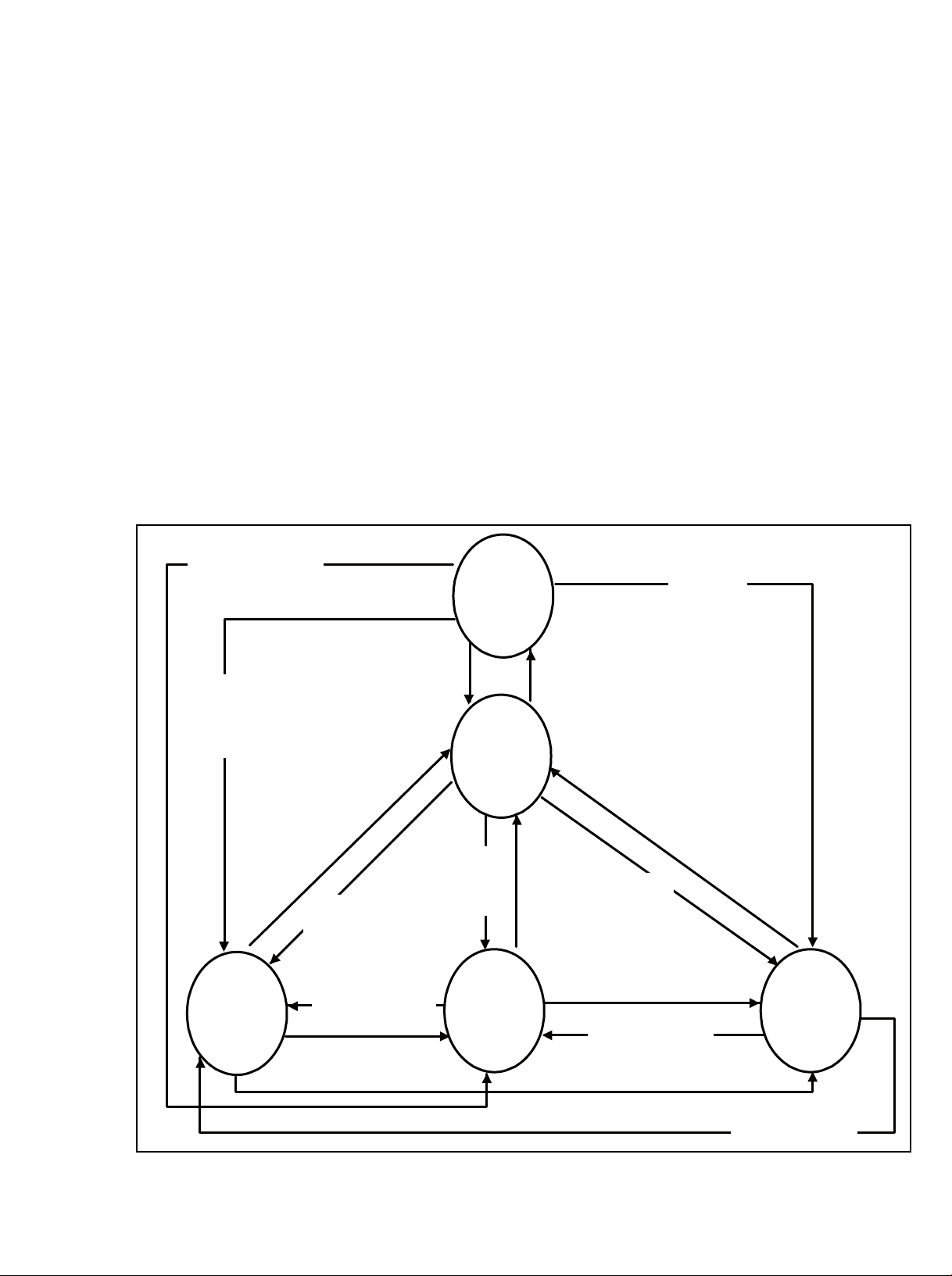
Figure 5-1 Stepwise Start-up
Page 6
5.4 Service Tools
5.5 Software Upgrading
5.4.1 ComPair
Introduction
ComPair (Computer Aided Repair) is a Service tool for Philips
Consumer Electronics products. and offers the following:
1. ComPair helps to quickly get an understanding on how to
repair the chassis in a short and effective way.
2. ComPair allows very detailed diagnostics and is therefore
capable of accurately indicating problem areas. No
knowledge on I
2
C or UART commands is necessary,
because ComPair takes care of this.
3. ComPair speeds up the repair time since it can
automatically communicate with the chassis (when the
micro processor is working) and all repair information is
directly available.
4. ComPair features TV software up possibilities.
Specifications
ComPair consists of a Windows based fault finding program
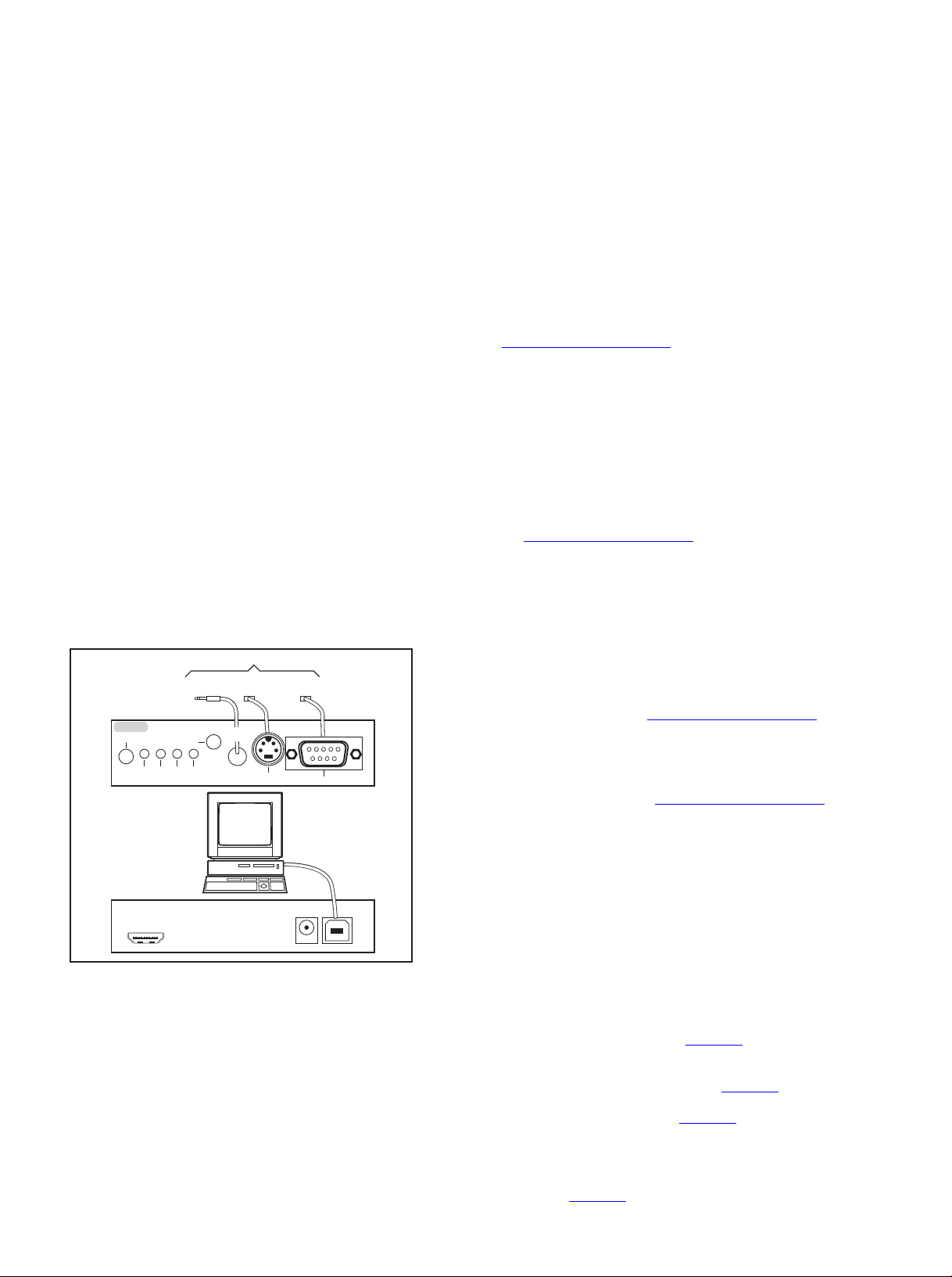
and an interface box between PC and the (defective) product.
The ComPair II interface box is connected to the PC via an
USB cable. For the TV chassis, the ComPair interface box and
the TV communicate via a bi-directional cable via the service
connector(s).
The ComPair fault finding program is able to determine the
problem of the defective television, by a combination of
automatic diagnostics and an interactive question/answer
procedure.
How to Connect
This is described in the chassis fault finding database in
ComPair.
TO TV
TO
TO
UART SERVICE
CONNECTOR
2
I
C
RS232 /UART
ComPair II Developed by Philips Brugge
Optional power
5V DC
ComPair II
RC in
Optional
Switch
Power ModeLink/
Activity
HDMI
2
I
C only
UART SERVICE
CONNECTOR
RC out
TO
I2C SERVICE
CONNECTOR
Multi
function
PC
5.5.1 Description
It is possible for the user to upgrade the main software via the
USB port. This allows replacement of a software image in a
stand alone set. A description on how to upgrade the main
software can be found in the DFU or on the Philips website.
5.5.2 Introduction
Philips continuously tries to improve its products, and it’s
recommend that the TV software is updated when updates are
available. Software update files can be obtained from the
dealer or can be downloaded from the following websites:
http://www.philips.com/support
Preparing a portable memory for software upgrade
The following requirements have to be met:
1. A personal computer connected to the internet.
2. An archive utility that supports the ZIP-format (e.g. WinZip
for Windows or Stufflt for Mac OS).
3. A FAT formatted USB memory stick (preferably empty).
Note:
1. Only FAT/DOS-formatted memory sticks are supported.
2. Only use software update files that can be found on the
http://www.philips.com/support
web site.
5.5.3 Check the current TV software version
Before starting the software upgrade procedure, it is advised to
check that what the current TV software:
1. Press the “1 2 3 6 5 4” button on the remote control to enter
the CSM mode.
2. Use the up/down cursor keys to select “Current Main
Software”.
If the current software version of the TV is the same as the
latest update file found on http://www.philips.com/support
not necessary to update the TV software.
5.5.4 Download the latest software
1. Open the internet page http://www.philips.com/support
2. Find information and software related to the TV.
3. Select the latest software update file and download it to the
PC.
4. Insert the USB memory stick into one of the USB ports of
the PC.
5. Decompress the downloaded ZIP file and copy the
“autorun.upg” to the root directory of the USB flash drive.
5.5.5 Update the TV software
, it is
.
10000_036_090121.eps
091118
Figure 5-2 ComPair II interface connection
Caution: It is compulsory to connect the TV to the PC as
shown in the picture above (with the ComPair interface in
between), as the ComPair interface acts as a level shifter. If
one connects the TV directly to the PC (via UART), ICs can be
blown!
How to Order
ComPair II order codes:
• ComPair II interface: 3122 785 91020.
• Software is available via the Philips Service web portal.
• ComPair UART interface cable for TPM9.1x xx.
(using DB9 to 2mm pitch JST connector): 3122 785 90630.
Note: When you encounter problems, contact your local
support desk.
1. Turn the TV on and wait for it to boot completely.
2. Insert the USB memory stick that contains the software
update files in the TV’s USB port.
3. The TV will detect the USB memory stick automatically.
Then a window jumps out as Figure 5-3
.
Note: If the USB flash drive is not detected after power up,
disconnect it and re-insert it.
4. Select [Update] and press OK. See Figure 5-3
.
5. To proceed, In next menu select [Start] and press OK to
start software updates. See Figure 5-4
.
6. Upgrading will now begins and the status of the updating
progress will be displayed.
7. When the TV software is updated. Remove your USB flash
drive, then select [Restart] and press OK to restart the
TV.See Figure 5-5
.
Page 7
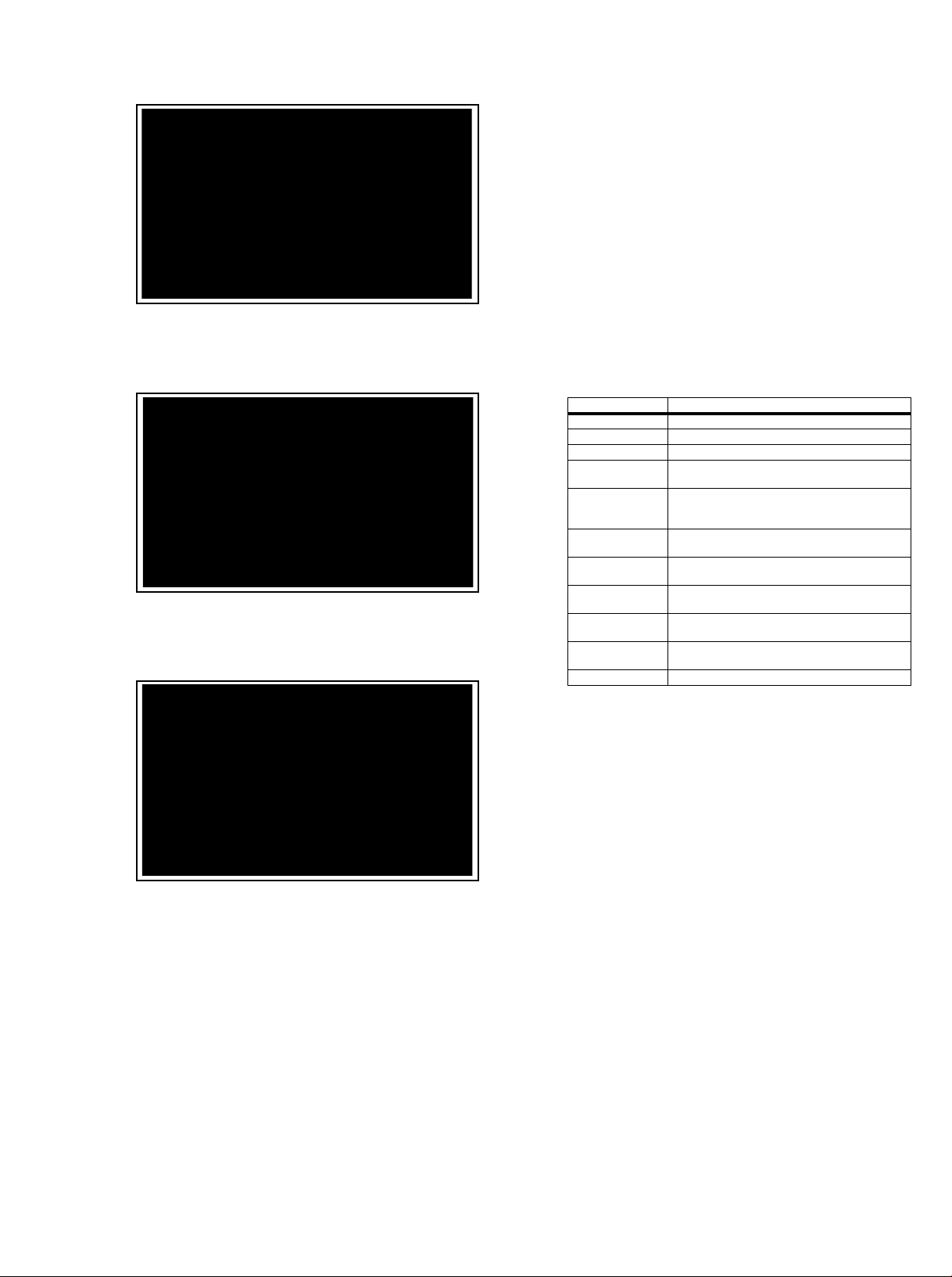
Figure 5-3 Update the TV software [1/3]
19080_207_110324.eps
110324
19080_208_110324.eps
110324
19080_209_110324.eps
110324
Figure 5-4 Update the TV software [2/3]
• FUS_clustername_version.zip: Contains the
“autorun.upg” which is needed to upgrade the TV main
software and the software download application.
• NVM_clustername_version.zip: Default NVM content.
Must be programmed via ComPair.
5.5.7 How to Copy NVM Data to/from USB
When copying data to and from a USB memory stick, the folder
“repair” is used. When inserting an empty USB memory stick,
and downloading data to the stick, the TV will create this folder.
When sending data from a USB memory stick to a TV, the
intended data must be available in the “repair” folder.
Note that when copying EDID data to the TV, all necessary
EDID files must be in this folder.
Service mode overview for your reference.
Table 5-3 Service mode overview
Service Modes Description
SAM Service alignment mode
Factory Mode Used for extended alignments
SDM Service default Mode
CSM 3-page compact CSM pages. There will be CSM dump to
USB SW upgradeable SW-upgrading of flash memories M TK-chips MT5366 can
NVM-Editor in SAM NVM-editor will function as in the past: Address and Value
Service Data New Service data in SAM for CTN, Prod. no., 12NC
USB copy/paste in
SAM
UART logging There will be printout available in UART. No specifications
Blind SAM RC sequence “062598” + “Menu” +
Clear Buffer RC sequence “062599” + “OK” or via SAM
USB-stick upon entering CSM-mode
be done via USB. The main SW can be upgraded via
Autorun.upg
field is a decimal value via digit entry
programming with virtual key board
Channel list, NVM data, Readable info, EDID
of the printout, per MTK provision/definition.
“Panel code”
Figure 5-5 Update the TV software [3/3]
Note:
• Do not remove the USB flash drive during the software
update.
• If a power failure occurs during the update, do not remove
the USB flash drive from the TV. The TV will continue the
software update as soon as the power comes up again.
• If an error occurs during the update retry the procedure or
contact the dealer.
• We do not recommend downgrading to an older version.
• Once the upgrade is finished, use the PC to remove the TV
software from the USB portable memory.
5.5.6 Content and Usage of the One-Zip Software File
Below you find a content explanation of the One-Zip file, and
instructions on how and when to use it. Only files that are
relevant for Service are mentioned here.
• EDID_clustername.zip: Contains the EDID content of the
different EDID NVMs. See ComPair for further instructions.
5.6 Error Codes
5.6.1 Introduction
Error codes are required to indicate failures in the TV set. In
principle a unique error code is available for every:
• Activated (SW) protection.
• Failing I
• General I
The last five errors, stored in the NVM, are shown in the
Service menu’s. This is called the error buffer.
The error code buffer contains all errors detected since the last
time the buffer was erased. The buffer is written from left to
right. When an error occurs that is not yet in the error code
buffer, it is displayed at the left side and all other errors shift one
position to the right.
An error will be added to the buffer if this error differs from any
error in the buffer. The last found error is displayed on the left.
An error with a designated error code never leads to a
deadlock situation. It must always be diagnosable (e.g. error
buffer via OSD or blinking LED or via ComPair).
In case a failure identified by an error code automatically
results in other error codes (cause and effect), only the error
code of the MAIN failure is displayed.
5.6.2 How to Read the Error Buffer
You can read the error buffer in three ways:
• On screen via the SAM/SDM/CSM (if you have a picture).
2
C device.
2
C error.
Example:
– ERROR: 000 000 000 000 000: No errors detected
– ERROR: 013 000 000 000 000: Error code 13 is the
last and only detected error
Page 8
– ERROR: 034 013 000 000 000: Error code 13 was
detected first and error code 34 is the last detected
(newest) error
• Via the blinking LED procedure (when you have no
picture). See paragraph 5.5 Software Upgrading
.
•Via ComPair.
• It is assumed that the components are mounted correctly
with correct values and no bad solder joints.
• Before any fault finding actions, check if the correct options
are set.
5.8.1 NVM Editor
5.6.3 Error codes
In this chassis only “layer 2” error codes are available and point
to problems on the SSB. They are triggered by LED blinking
when CSM is activated. Only the following layer 2 errors are
defined:
Table 5-4 Error code table
Layer-2 error code Defective device
13 General I2C bus error on the SSB
16 +12 V missing or low, PSU defective
27 Channel decoder error on the SSB
34 Tuner I2C bus error on the SSB
35 EEPROM I2C error on SSB, M24C64
5.6.4 How to Clear the Error Buffer
The error code buffer is cleared in the following cases:
• By using the CLEAR command in the SAM menu
• By using the CLEAR command in the Factory mode:
• By using the following key sequence on the remote control
transmitter: “062599” directly followed by the OK button.
• If the contents of the error buffer have not changed for 50
hours, the error buffer resets automatically.
Note: If you exit SAM by disconnecting the mains from the
television set, the error buffer is not reset.
5.7 The Blinking LED Procedure
5.7.1 Introduction
In some cases, it can be convenient if one directly can change
the NVM contents. This can be done with the “NVM Editor” in
SAM mode. With this option, single bytes can be changed.
Caution:
• Do not change these, without understanding the function of
each setting, because incorrect NVM settings may
seriously hamper the correct functioning of the TV set!
• Always write down the existing NVM settings, before
changing the settings. This will enable you to return to the
original settings, if the new settings turn out to be incorrect.
5.8.2 Load Default NVM Values
It is possible to upload the default values to the NVM with
ComPair in case the SW is changed, the NVM is replaced with
a new (empty) one, or when the NVM content is corrupted.
After replacing an EEPROM (or with a defective/no EEPROM),
default settings should be used to enable the set to start-up and
allow the Service Default Mode and Service Alignment Mode to
be accessed.
5.8.3 No Picture
When you have no picture, first make sure you have entered
the correct display code. See paragraph 6.4 Option Settings
the instructions. See also Table 6-3
.
5.8.4 Unstable Picture via HDMI input
Check (via ComPair or factory mode) if HDMI EDID data is
properly programmed.
for
The software is capable of identifying different kinds of errors.
Because it is possible that more than one error can occur over
time, an error buffer is available, which is capable of storing the
last five errors that occurred. This is useful if the OSD is not
working properly.
Errors can also be displayed by the blinking LED procedure.
The method is to repeatedly let the front LED pulse with as
many pulses as the error code number, followed by a period of
1.5 seconds in which the LED is “off”. Then this sequence is
repeated.
Example (1): error code 4 will result in four times the sequence
LED “on” for 0.25 seconds / LED “off” for 0.25 seconds. After
this sequence, the LED will be “off” for 1.5 seconds. Any RC
command terminates the sequence. Error code LED blinking is
in red color.
Example (2): the content of the error buffer is “12 9 6 0 0” After
entering SDM, the following occurs.
• 1 long blink of 5 seconds to start the sequence.
• 12 short blinks followed by a pause of 1.5 seconds.
• 9 short blinks followed by a pause of 1.5 seconds.
• 6 short blinks followed by a pause of 1.5 seconds.
• 1 long blink of 1.5 seconds to finish the sequence.
• The sequence starts again with 12 short blinks.
5.7.2 Displaying the Entire Error Buffer
Additionally, the entire error buffer is displayed when Service
Mode “SDM” is entered.
5.8 Fault Finding and Repair Tips
Note:
5.8.5 No Picture via HDMI input
Check if HDCP key is valid. This can be done in CSM.
5.8.6 TV Will Not Start-up from Stand-by
Possible Stand-by Controller failure. Re-flash the software.
5.8.7 Audio Amplifier
The Class D-IC U6002 has a powerpad for cooling. When the
IC is replaced it must be ensured that the powerpad is very well
pushed to the PWB while the solder is still liquid. This is needed
to insure that the cooling is guaranteed, otherwise the Class
D-IC could break down in short time.
5.8.8 CSM
When CSM is activated and there is a USB memory stick
connected to the TV, the software will dump the complete CSM
content to the USB memory stick. The file (Csm.txt) will be
saved in the root of the USB memory stick.
5.8.9 Loudspeakers
Make sure that the volume is set to minimum during
disconnecting the speakers in the ON-state of the TV. The
audio amplifier can be damaged by disconnecting the speakers
during ON-state of the set!
Page 9

5.8.10 Display option code
Attention: In case the SSB is replaced, always check the Panel
Code in CSM, even when picture is available. Performance
with the incorrect display option code can lead to unwanted
side-effects for certain conditions.
Page 10
6. Alignments
Index of this chapter:
6.1 General Alignment Conditions
6.2 Hardware Alignments
6.3 Software Alignments
6.4 Option Settings
6.5 Reset of Repaired SSB
6.1 General Alignment Conditions
Perform all electrical adjustments under the following
conditions:
• Power supply voltage: 90 - 264 V
• Connect the set to the mains via an isolation transformer
with low internal resistance.
• Allow the set to warm up for approximately 15 minutes.
• Measure voltages and waveforms in relation to correct
ground (e.g. measure audio signals in relation to
AUDIO_GND).
Caution: It is not allowed to use heat sinks as ground.
• Test probe: R
> 10 M, Ci < 20 pF.
i
• Use an isolated trimmer/screwdriver to perform
alignments.
, 50/ 60 3 Hz.
AC
In case you have a colour analyser:
• Measure with a calibrated (phosphor- independent) color
analyser (e.g. Minolta CA-210) in the centre of the screen.
Consequently, the measurement needs to be done in a
dark environment.
• Adjust the correct x,y coordinates (while holding one of the
White point registers R, G or B on max. value) by means of
decreasing the value of one or two other white points to the
correct x, y coordinates (see Table 6-1 White D alignment
values). Tolerance: dx: 0.010, dy: 0.010.
• Repeat this step for the other colour Temperatures that
need to be aligned.
• When finished return to the SAM root menu and press
STANDBY on the RC to store the aligned values to the
NVM.
Table 6-1 White D alignment values
Value Cool (11000 K) Normal (9000 K) Warm (6500 K)
x 0.276 0.287 0.313
y 0.282 0.296 0.329
6.2 Hardware Alignments
Not applicable.
6.3 Software Alignments
Put the set in SAM mode (see Chapter 5. Service Modes, Error
Codes, and Fault Finding). The SAM menu will now appear on
the screen. Select RGB Align and go to one of the sub menus.
The alignments are explained below.
The following items can be aligned:
• White point
To store the data:
• Press OK on the RC before the cursor is moved to the
left.
• Select “Store” and press OK on the RC.
• Switch the set to stand-by mode.
For the next alignments, supply the following test signals via a
video generator to the RF input:
• EU/AP-PAL models: a PAL B/G TV-signal with a signal
strength of at least 1 mV and a frequency of 475.25 MHz
• US/AP-NTSC models: an NTSC M/N TV-signal with a
signal strength of at least 1 mV and a frequency of
61.25 MHz (channel 3).
• LATAM models: an NTSC M TV-signal with a signal
strength of at least 1 mV and a frequency of
61.25 MHz (channel 3).
6.3.1 RGB Alignment
Before alignment, set the picture as follows:
Picture Setting
Dynamic backlight Off
Dynamic Contrast Off
Color Enhancement Off
Picture Format Unscaled
Light Sensor Off
Brightness 50
Color 0
Contrast 100
If you do not have a colour analyser, you can use the default
values. This is the next best solution. The default values are
average values coming from production (statistics).
6.3.2 Display Adjustment
You can use the default values. The default values are average
values coming from production.
• Enter SAM mode.
• Select a colour temperature (e.g. COOL, NORMAL, or
WARM).
• Set the RED, GREEN and BLUE default values according
to the values in Table 6-2
.
• When finished press OK on the RC, then press STORE to
store the aligned values to the NVM.
• Restore the initial picture settings after the alignments.
Table 6-2 White tone default settings
Picture mode Screen size
Normal (9000K) 32PFL3007 128 116 101
32PFL3017 128 116 101
37PFL3007 128 122 124
42PFL3007 128 122 124
47PFL3007 128 128 104
Cool (11000K) 32PFL3007 128 124 124
32PFL3017 128 124 123
37PFL3007 113 112 128
42PFL3007 110 114 128
47PFL3007 114 116 128
Warm (6500K) 32PFL3007 128 103 59
32PFL3017 128 104 59
37PFL3007 128 110 80
42PFL3007 128 114 78
47PFL3007 128 120 66
Colour temperature
Red Green Blue
This group setting of colour temperature will be applied
automatically to the TV / VGA / HDMI / AV sources.
White Tone Alignment:
• Activate SAM.
• Select “RGB Align.” and choose a color temperature.
• Use a 100% white screen as input signal and set the
following values:
– “Red BL Offset” and “Green BL Offset” to “7” (if
present).
– All “White point” values initial to “128”.
Page 11
6.4 Option Settings
6.5.1 SSB Indentification
6.4.1 Introduction
The microprocessor communicates with a large number of I
ICs in the set. To ensure good communication and to make
digital diagnosis possible, the microprocessor has to know
which ICs to address. The presence / absence of these
MT5366 ICs is made known by the option codes.
Notes:
• After changing the option(s), save them by pressing the OK
button on the RC before the cursor is moved to the left,
select STORE and press OK on the RC.
• The new option setting is only active after the TV is
switched “off” / “stand-by” and “on” again with the mains
switch (the NVM is then read again).
6.4.2 Option Code Overview
Enter SAM mode to check the option codes. they could not be
edited in the NVM.
6.4.3 Display Code Overview
Press the following key sequence on a standard RC
transmitter: “062598” directly followed by MENU and “xxx”,
where “xxx” is a 3 digit decimal value of the panel type: see
column “Display Code” in Table 6-3
. After resetting the Display
Code, restart the set immediately.
SSB’s of this chassis are identified by a “715” code on the SSB.
715Axxxx-Nnn-MMM-OOOO
2
C
• 715 main category, Printed Wiring Board
• Axxxx sub category, sequential coding number
• Nnn Version code
• N Development number
• nn Production number
• MMM Mounting variation code
• OOOO Optional variation code
Make sure when replacing an SSB the SSB identification codes
match the replacement board.
Table 6-3 Display code overview
CTN_ALT BOM# Panel Type Display Code
32PFL3007 LC320WXE-SCC1 154
32PFL3017 LC320WUE-SCA1 150
37PFL3007 LC370WUE-SCA1 151
42PFL3007 LC420WUE-SCA1 152
47PFL3007 LC470WUE-SCA2 153
6.5 Reset of Repaired SSB
A very important issue towards a repaired SSB from a Service
repair shop (SSB repair on component level) implies the reset
of the NVM on the SSB.
A repaired SSB in Service should get the service Set type
“00PF0000000000” and Production code “00000000000000”.
Also the virgin bit is to be set. To set all this, you can use the
ComPair tool or use the “NVM editor” and “Dealer options”
items in SAM (do not forget to “store”).
After a repaired SSB has been mounted in the set (set repair
on board level), the type number (CTN) and production code of
the TV has to be set according to the type plate of the set. For
this, you can use the NVM editor in SAM. The loading of the
CTN and production code can also be done via ComPair
(Model number programming).
In case of a display replacement, reset the “Operation hours
display” to “0”, or to the operation hours of the replacement
display.
 Loading...