

Philips TFT LCD Colour Monitor Service Manual
19” TFT LCD Colour Monitor
Service Manual
Horizontal frequencies
30 - 82KHz
TABLE OF CONTENTS
Description Page
Important Safety Notice
Technical Data & Power Management ------------------- 3 ~ 4 DDC Data
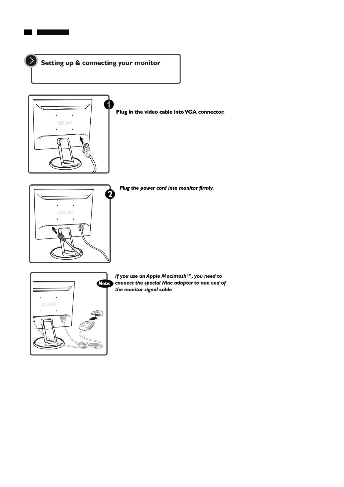
Connection to PC
Installation & Acce ssories
Description of Controls
Advanced Control of OSD
Clock & Phase Adjustment s
OSD Menu Control Level Structure ----------------------- 13 P ower board ----------------------------------- ----------------- 47
OSD Att ention Signal ------ ----------------- ------------------ 14 Input D-SUB Diagram
Troubleshooting
Failure Mode of LCD Panel --------------------------------- 16 AC Adaptor Diagram
Definition of Pixel Defects ------------------------- ---------- 17 M C U & Scaler Diagram
Wiring Diagram
Mechanical Instructions
Electrical Instructions
Factory Adju stment
Safety Test Requ ir eme nt s -- ---------------- --- -- --- --- --- --- 27 ISP Procedure --------- --- --- --- -- - --- --- --- --- --- --- --- --- -- -- 78~81
------------------------------------------------ 18 Inverter Diagram(Ambit) ------------------------------------- 56~57
---------------- ------ ------ --- ------ - 2 DDC Instructions ----------------------------------------------- 28
---------------------------------------------- 5~7 Repair Flow Chart --------------------------------------------- 31~33
---------------------- ------ --- ---- 8 Colour Adjustment --------------------------------------------- 34~41
-------------------- ------ --- ------ ---- 9 Repair tips ------------------------------------------------------- 42
------------------------ ----------- 10 Block Diagram and control panel -------------------------- 43~45
------------------- ------------- 11~12 Scaler board -------------------------- --------------------- ----- 46
----------------------------------------- --- ---- 15 DC-DC conv erte r Diag ra m ---------------------------------- 50~51
-------------------------------------- 19~24 Exploded View ------------------------------------------------- 58~60
---------------------- --- ------ ------ --- - 25 Spare Parts List ----------------------------------------------- 61~65
-------------------------------------------- 26 General Product Specification ------------------------------ 66~77
Description Page
------------------------------------------------------- 29~30
---------------------------------------- 48~49
------------------------------------------ 52~53
-------------------------------------- 54~55
ANY PERSON ATTEMPTING TO SERVICE THIS CHASSIS MUST FAMILIARIZE HIMSELF WITH THE CHASSIS
AND BE AWARE OF THE NECESSARY SAFETY PRECAUTIONS TO BE USED WHEN SERVICING ELECTRONIC
EQUIPMENT CONTAINING HIGH VOLTAGES.
CAUTION: USE A SEPARATE ISOLATION TRANSFORMER FOR THIS UNIT WHEN SERVICING.
REFER TO BACK CO VER FOR IMPORTANT SAFETY GUIDELINE S
http://www.wjel.net
CD-ROM : 3136 106 10287
Service Manual : 3136 106 10288

2 190B4 LCD
Important Safety Notice
Proper service and repair is important to the safe, reliable
operation of all Philips Consumer Electronics Company**
Equipment. The service procedures recommended by Philips
and described in this service manual are effective methods of
performing service operations. Some of these service
operations require the use of tools specially designed for the
purpose. The special tools should be used when and as
recommended.
It is important to note that this manual contains various
CAUTIONS and NOTICES which should be carefully read in
order to minimize the risk of personal injury to service
personnel. The possibility exists that improper service methods
may damage the equipment. It is also important to understand
that these CAUTIONS and NOTICES ARE NOT EXHAUSTIVE.
Philips could not possibly know, evaluate and advise the
service trade of all conceivable ways in which service might be
done or of the possible hazardous consequences of each way.
Consequently, Philips has not undertaken any such broad
evaluation. Accordingly, a servicer who uses a service
procedure or tool which is not recommended by Philips must
first satisfy himself thoroughly that neither his safety nor the
safe operation of the equipment will be jeopardized by the
service method selected.
* * Hereafter throughout this manual, Philips Consumer
Electronics Company will be referred to as Philips.
WARNING
Critical components having special safety characteristics are
identified with a
enclosed within a broken line*
(where several critical components are grouped in one area)
along with the safety symbol
exploded views.
User of substitute replacement parts which do not have the
same specified safety characteristics may create shock, fire, or
other hazards.
Under no circumstances should the original design be modified
or altered without written permission from Philips. Philips
assumes no liability, express or implied, arising out of any
unauthorized modification of design.
Servicer assumes all liability.
* Broken Line
by the Ref. No. in the parts list and
on the schematics or
http://www.wjel.net
FOR PRODUCTS CONTAINING LASER:
DANGER - invisible laser radiation when open.
AVOID DIRECT EXPOSURE TO BEAM.
CAUTION - Use of controls or adjustments or performance of
procedures other than those specified herein
may result in hazardous radiation exposure.
CAUTION - The use of optical instruments with this product
will increase eye hazard.
To ENSURE THE CONTINUED DELIABILITY OF THIS
PRODUCT, USE ONLY ORIGINAL MANUFACTURER’S
REPLACEMENT PARTS, WHICH ARE LISTED WITH THEIR
PART NUMBERS IN THE PARTS LIST SECTION OF THIS
SERVICE MANUAL.
Take care during handling the LCD module with backlight
unit
- Must mount the module using mounting holes arranged in
four corners.
- Do not press on the panel, edge of the frame strongly or
electric shock as this will result in damage to the screen.
- Do not scratch or press on the panel with any sharp objects,
such as pencil or pen as this may result in damage to the
panel.
- Protect the module from the ESD as it may damage the
electronic circuit (C-MOS).
- Make certain that treatment person’s body are grounded
through wrist band.
- Do not leave the module in high temperature and in areas of
high humidity for a ling time.
- Avoid contact with water as it may a short circuit within the
module.
- If the surface of panel become dirty, please wipe it off with a
soft material. (Cleaning with a dirty or rough cloth may
damage the panel.)
3 190B4 LCD
Technical Data
Technical Specifications
LCD Panel
Screen type :CMO Active matrix – TFT LCD
Screen dimensions
Preset display area
Horizontal :376.32mm
Vertical :301.056mm
Pixel pitch :0.294 x 0.294mm
Viewing angle (CR>10) :Upper≥85°(typ.) Lower≥85°(type)
:Left and Right ≥ 85° (typ.)
Display Colors :8 bits interface (16M colors)
SCANNING
Horizontal scan range :30KHz to 82KHz (automatic)
Vertical scan rang :56Hz to 76Hz (automatic)
Optimal preset resolution
Highest preset resolution :1280 x 1024 at 75Hz
Video
Video dot rate :135MHz
Input impedance
- Video :75 ohms
- Sync :2K ohms
Input signal levels :700m Vpp
Synchronization input signals :Separate horizontal and vertical
Input Frequency :SXVG Hsync 63-80KHz
Video interface :Analog (D-Sub)
Resolution and Preset Modes
Maximum
Recommended :1280 x 1024 at 60Hz
Physical Characteristics
Dimensions
Height :452.2mm
Depth :235.0mm
Width :425.0mm
Weight (monitor only) :7.0kg
:
19 inches (diagonal)
:
1280 x 1024 at 60Hz
/ composite; TTL level, positive
or negative, Sync On Green
Vsync 60-76Hz (N.I.)
XGA Hsync 48-61KHz
Vsync 60-76Hz (N.I.)
VGA Hsync 31-38Hz (N.I.)
Vsync 60-76Hz (N.I.)
:
1280 x 1024 at 75Hz
http://www.wjel.net
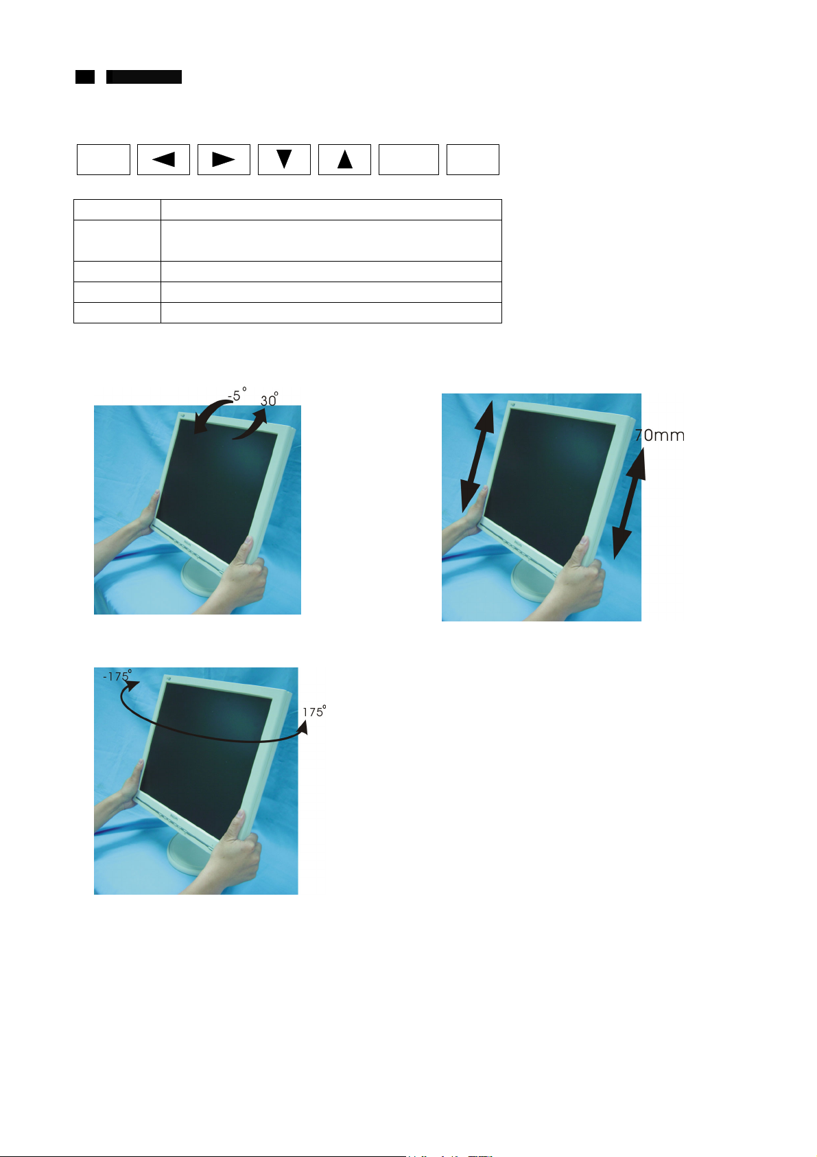
Tilt and swivel angle of pedestal:+/- 175
Height adjustment range
Portrait display :0° rotation counter clockwise
Forward / Backward :-5° / 30°
AC input voltage / frequency
Power consumption :< 45W
Operating :5℃ to 35℃ (41℉ to 95℉)
Humidity
Operating :20% to 80%
System MTBF :50Khrs (CCFL 50Khrs)
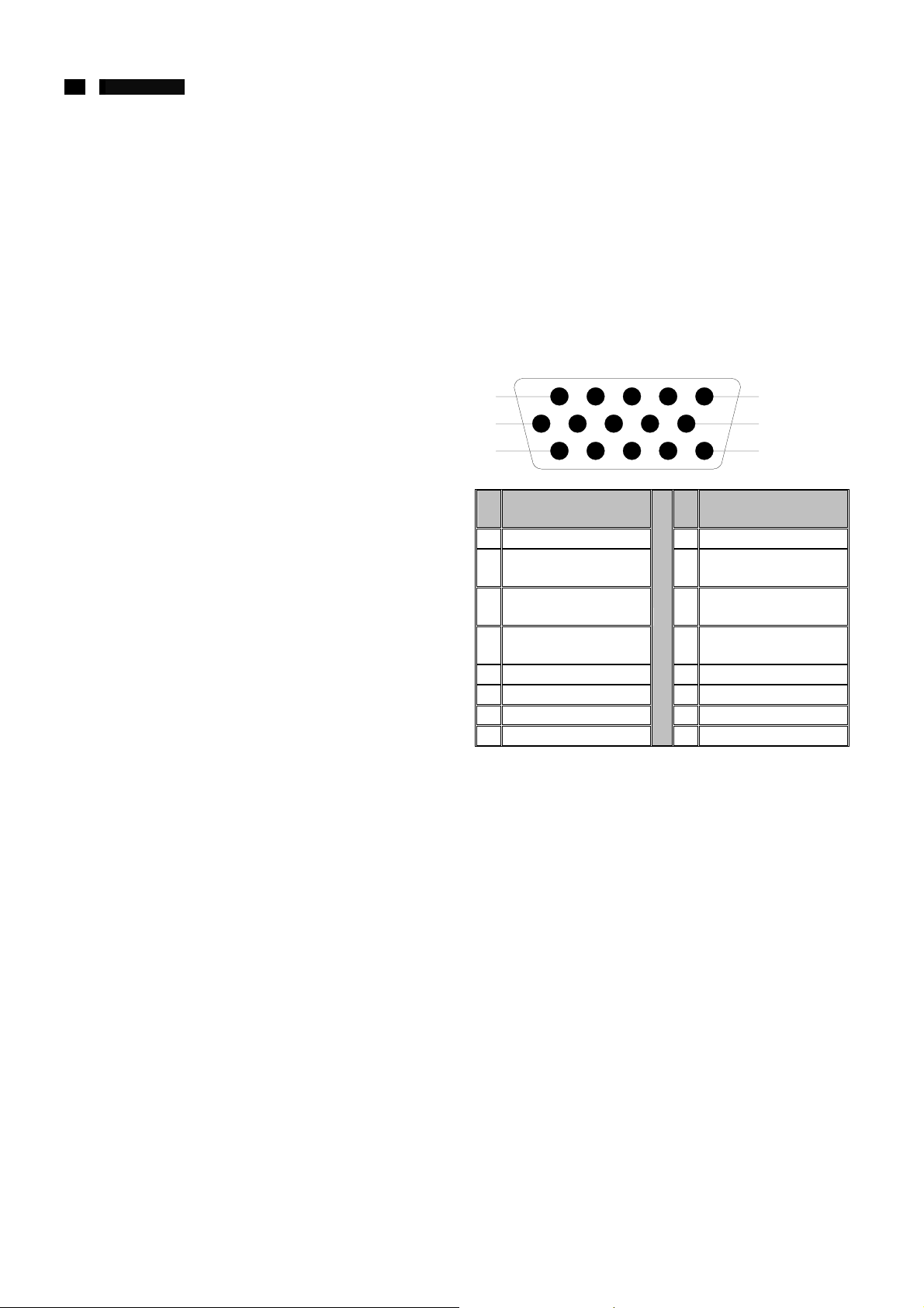
The 15pin D-sub connector (male)of the signal cable
1
6
11
Pin
Assignment
No.
1 Red video input 9 DDC +5V
2 Green video input 10
3 Blue video input 11
Identical output
4
connected to pin 10
5 GND 13 H. Sync / H+V
6 Red video ground 14 V. Sync
7 Green video ground 15 Data clock line (SCL)
8 Blue video ground
:
70mm
:
90 to 264VAC / 50 or 60Hz
5
10
15
Pin
Assignment
No.
Logic ground - cable
detect
Identical output
connected to pin 10
12 Serial data line (SDA)
4 190B4 LCD
Technical Data
Automatic Power Saving
If you have VESA’s DPMS compliance display card or software
installed in your PC, the monitor can automatically reduce
power consumption when power saving function active. And if
an input from keyboard, mouse or other input devices is
detected, the monitor will automatically “wake up”. The
following table shows the power consumption and signaling of
this automatic power saving feature:
Power Management Deflinition
Ves a’s
mode
Stand-by Blanked No Yes <1W Amber <3s
Suspend Blanked Yes No <1W Amber <3s
OFF Blanked No No <1W Amber <3s
This monitor is Environmental Protection Agency (EPA) Energy
Star compliant and TCO’99 power management compatible.
*Zero power consumption in OFF mode can only be achieved
by disconnecting the mains cable from the monitor.
ENERGY STAR is a U.S registered mark. AS AN ENERGY
STAR PARTNER, PHILIPS HAS DETERMINED THAT THIS
PRODUCT MEETS THE ENERGY STAR GUIDELINES FOR
ENERGY EFFICIENCY.
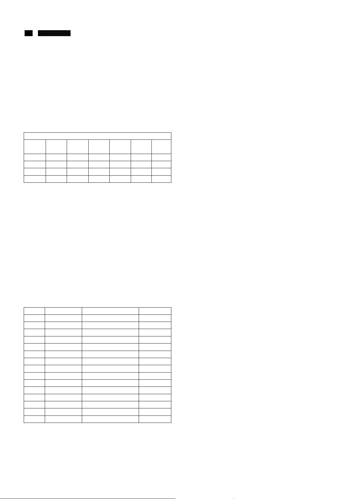
Data Storage
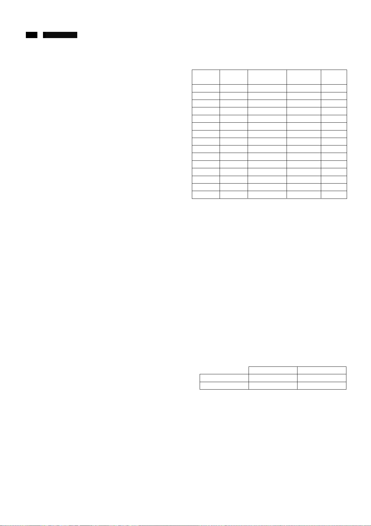
Factory preset mode:
This monitor has 15 factory-preset modes as indicated in the
following table:
Mode Resolution H. freq. / V. freq Standard
Meanwhile, it also reverse 15 sets data space available for user
storage new timings data.
VIDEO H-SYNC V-SYNC
ON Active Yes Yes <45W Green
1 640 x 350 31.469KHz/70.087Hz VGA
2 720 x 400 31.469KHz/70.087Hz VGA
3 640 x 480 31.469KHz/59.940Hz VGA
4 640 x 480 35.000KHz/66.667Hz Macintosh
5 640 x 480 37.500KHz/75.000Hz VESA
6 800 x 600 31.156KHz/56.250Hz VESA
7 800 x 600 37.879KHz/60.317Hz VESA
8 800 x 600 46.875KHz/75.000Hz VESA
9 832 x 624 49.700KHz/75.000Hz Macintosh
10 1024 x 768 48.363KHz/60.004Hz VESA
11 1024 x 768 60.023KHz/75.029Hz VESA
12 1152 x 870 68.700KHz/75.000Hz Macintosh
13 1152 x 900 71.810KHz/76.150Hz SUN WS
14 1280 x 1024 63.981KHz/60.020Hz VESA
15 1280 x 1024 79.976KHz/75.025Hz VESA
http://www.wjel.net
POWER
SUED
LED
COLOR
REC
TIME
―
5 190B4 LCD
Connection to PC
http://www.wjel.net
6 190B4 LCD
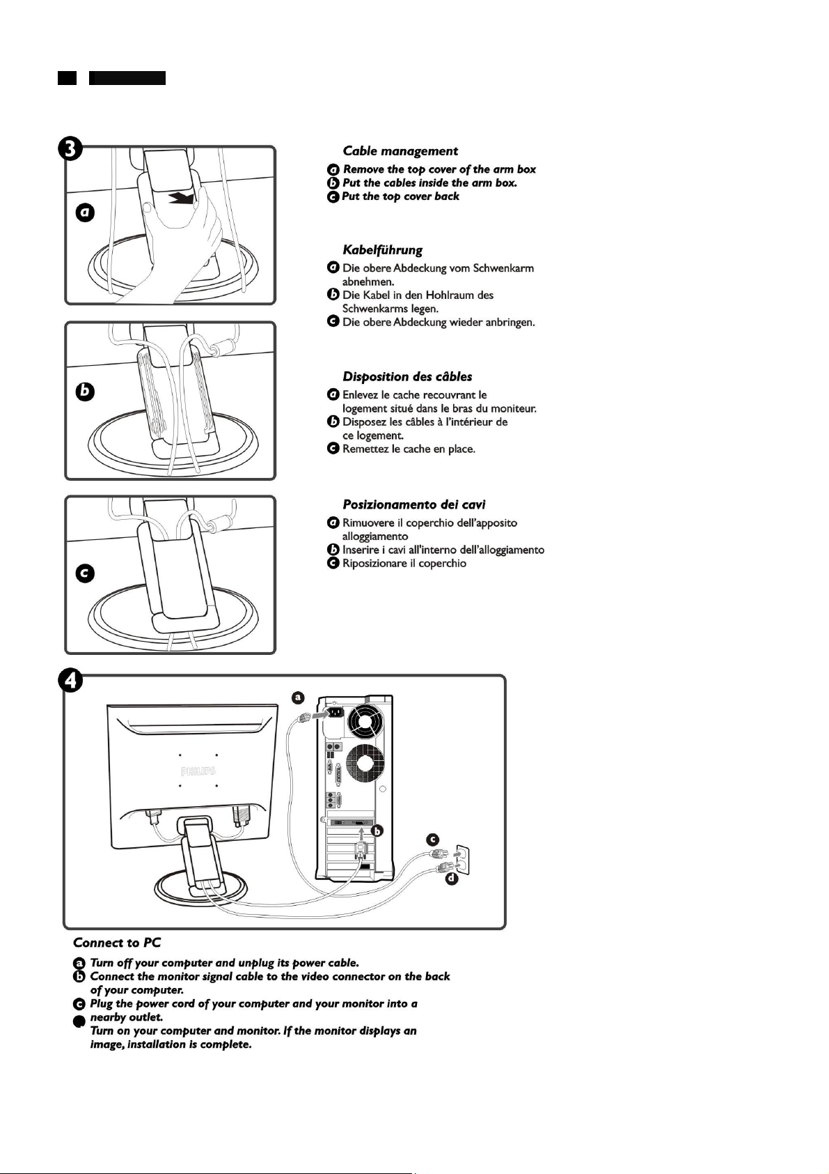
Connection to PC
http://www.wjel.net
7 190B4 LCD
Connection to PC
http://www.wjel.net
8 190B4 LCD
Installation & Accessories
Installation Locations
Avoid Heat and Extreme Cold
1. Do not store or use the LCD monitor in locations exposed to heat, direct sunlight, or extreme cold.
2. Avoid moving the LCD monitor between locations with large temperature differences. Choose a site falling with in the
following temperature and humidity ranges.
Temperature: 5-35°C 41-95°F
Humidity:20-80% RH
3. Do not subject the LCD monitor to severe vibration or high impact conditions. Do not place the LCD monitor inside a car trunk.
4. Take care not mishandle this product by either knocking or dropping during operation or transportation.
5. Do not store or use the LCD monitor in locations exposed to high humidity or a dusty environment. Also do not allow water or
other liquids to spill on or into the LCD monitor
Correct handling of the monitor
1. When handling the monitor, grip the bottom firmly with both hands and ensure that the front panel faces outward before lifting.
Please refer to the diagram on the right.
2. Handling the monitor with carp prevents scratching and damage. If the monitor becomes damaged, immediately disconnect
the power from the unit and have it checked by a qualified service person before using it again.
3. To prevent fire or electrical shock, do not drop the monitor.
4. When moving the monitor, be sure to unplug all power cords in order to avoid injury or damage to the equipment.
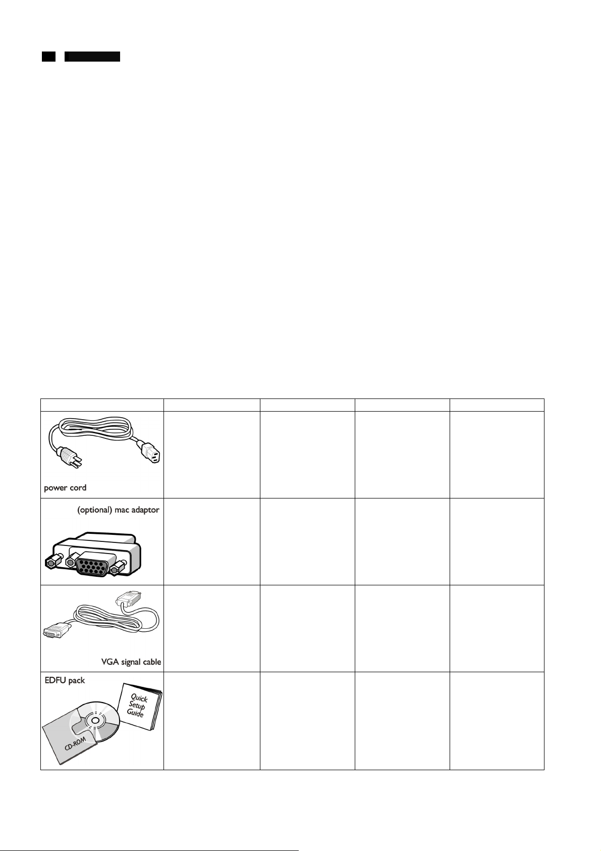
Accessory Pack
Unpack all parts.
Item Description 190B4CG 190B4CS 190B4CB
Power Cable(socket may
differ for different
countries)
Macintosh Adapter(for
USA only)
VGA Signal Cable
http://www.wjel.net
E-DFU package with Quick
Setup Guide, Using Your
Monitor Manual, and
CD-ROM
v v v
v v v
Only for US Model Only for US Model Only for US Model
v v v
9 190B4 LCD
AUTO
OK
Up & Down
Right & Left
AUTO
Power
Entering OSD main control & confirming selection
1. to select the item for screen settings through OSD menu
2. to directly access screen brightness adjustment
To adjust settings through OSD menu
To optimize the screen picture quality & position
switches your monitor On/Off.
Physical Function
1) Tilt
Description of Controls
MENU/OK
Power
3) Height Adjustment
2) Swivel
http://www.wjel.net
10 190B4 LCD
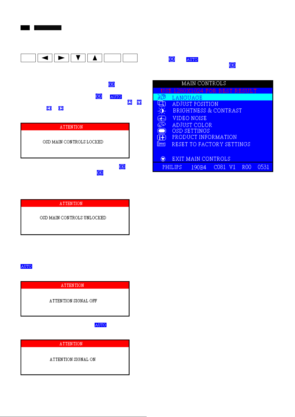
Advanced control of OSD
Front control panel
AUTO
To Lock/Unlock OSD function
The OSD function can be locked by pressing
more than 10 seconds, the screen shows following windows for
3 seconds. Everytime when you press
this message appears on the screen automatically. The
(brightness),
brightness and mute expectively while OSD locked.
Locked OSD function can be released by pressing
for more than 10 seconds. While press
unlocked purpose, the screen will keep showing “OSD MAIN
MENU LOCKED” until OSD function unlocked and screen
automatically shows following window for 3 seconds.
& (mute) hotkey are still functional for
MENU/OK
or button,
button for OSD
Power
button for
&
button
Access Factory Mode
To hold
time) then power on the monitor. Press
menu for confirmation as below:
and buttons (Don’t press other key at same
to bring up OSD
Switch ON/OFF attention signals
All attention signals can be switched off by keep pressing
button for more than 10 seconds if there is no video
signal supplied.
http://www.wjel.net
Recover attention signals by pressing
than 10 seconds without video signal input.
button for more
11 190B4 LCD
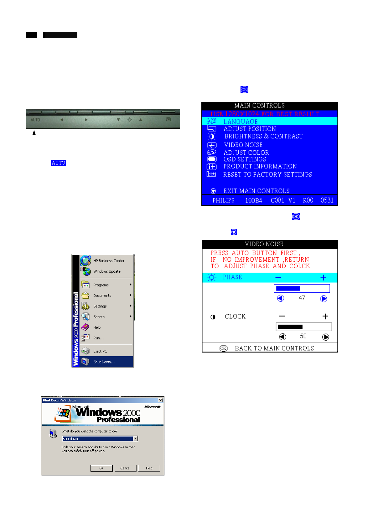
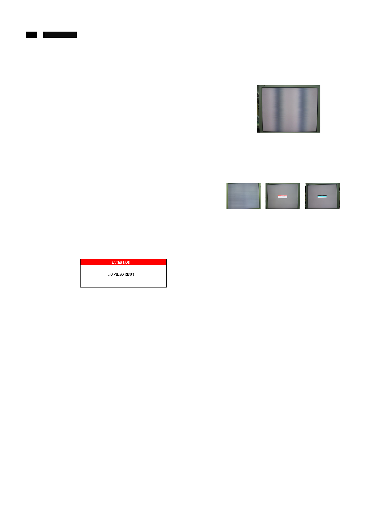
CLOCK & PHASE Adjustments
Due to the different quality of video signal generated from
graphics cards. It is necessary to adjust CLOCK and PHASE
functions for the optimal video display of LCD monitor.
Following steps will guide you to make correct adjustment of
CLOCK and PHASE.
Auto adjustment hotkey
The 190B4 has build-in a auto adjustment hotkey on the front
panel, you may obtained a optimal video display by simply
press the
PHASE, Vertical position, and Horizontal position are adjusted
automatically.
Manual adjustment
If the quality of display still poor or flicker, you may also improve
it by manual adjust CLOCK and PHASE functions to eliminate
the flicker.
Step 1: Click on the Start button (Win95, Win98 or Win NT)
button and save the settings. CLOCK,
and choose “Shut Down…”. As shown in Fig.1
Step 3: Remaining Shut Down Window on the screen, follow
the CLOCK and PHASE adjustment instructions for
the optimal video display.
Step 4: Press the
button to bring up OSD menu.
Step 5: Select VIDEO NOISE by press
Step 6: Press
for bring up it’s submenu.
button.
Step 2: The menu of “Shut Down Windows” is as shown in
Fig.2
http://www.wjel.net
12 190B4 LCD
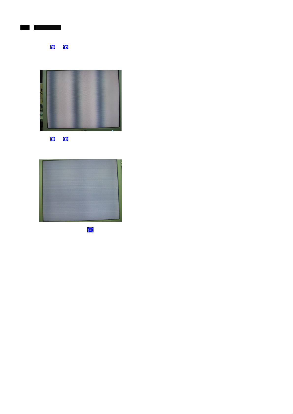
CLOCK & PHASE Adjustments
Step 7: Press or to adjust CLOCK. The picture will be
jitter as following figure, adjust CLOCK and check the
picture, stop at the point that without any vertical jitter
bar remaining on the
Step 8: Press
following figure, adjust PHASE to tune the video until
optimal display is obtained.
Stop 9: Quit OSD menu by press
settings.
or to adjust PHASE. The will be jitter as
button to save the
http://www.wjel.net
13 190B4 LCD
N
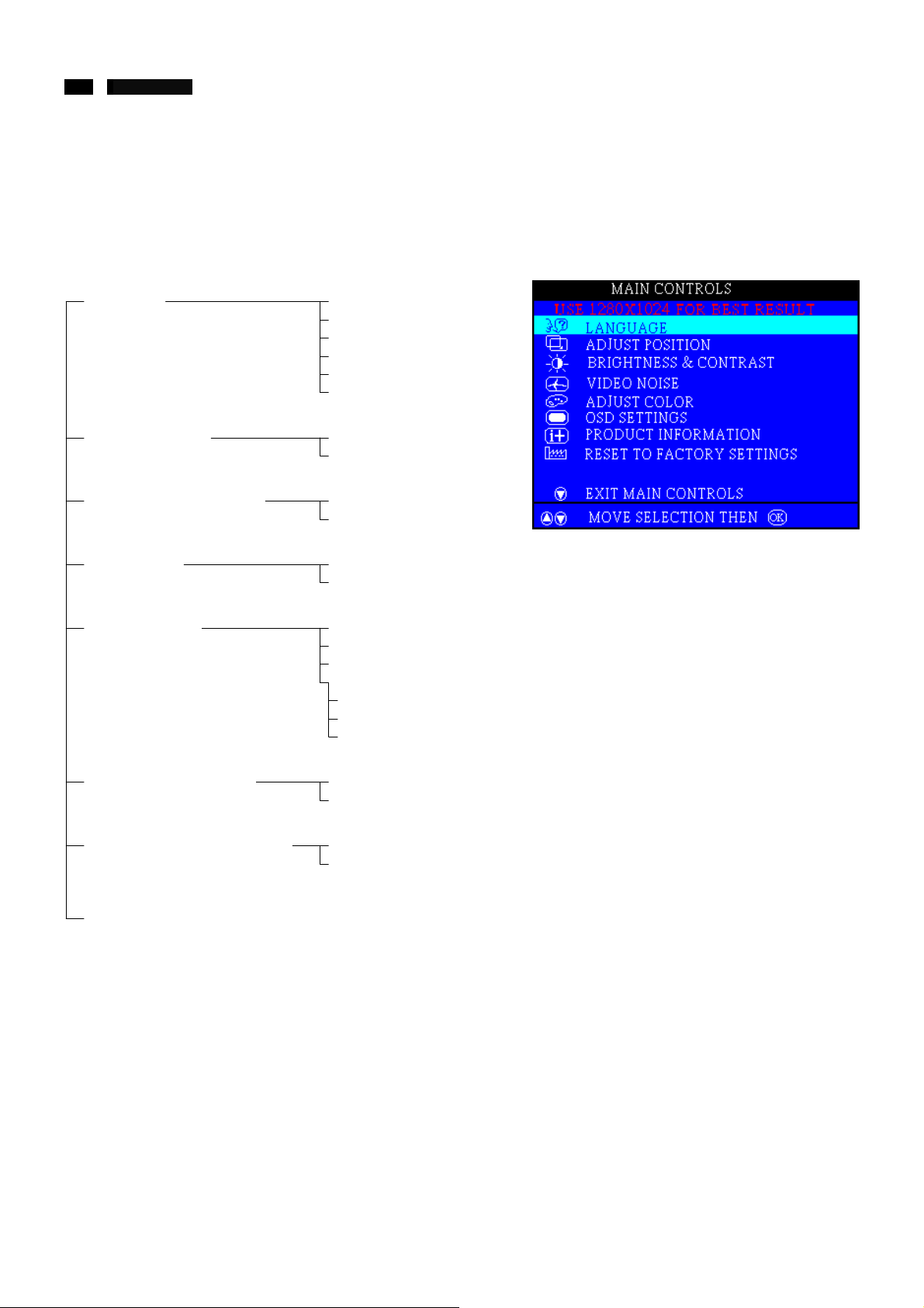
OSD Control Structure for Digital
The OSD Tree for analog video signal
Below is an overall view of the structure of the On-Screen Display. You can use this as reference when you want to later on work
your way around the different adjustments.
First Level Second Level
LANGUAGE
ADJUST POSITION
BRIGHTNESS & CONTRAST
VIDEO NOISE
ADJUST COLOR
ENGLISH
ESPANOL
FRANCAIS
DEUTSCH
ITALIANO
中語
HORIZONTAL
VERTICAL
BRIGHTNESS
CONTRAST
OSD Menu (Analog)
PHASE
CLOCK
ORIGINAL PANEL COLOR
9300K FOR CAD/CAM
6500 FOR IMAGE MANAGEME
USER PRESET
RED
GREEN
BLUE
PRODUCT INFORMATION
RESET TO FACTORY SETTING
CLOSE MAIN CONTROLS
SERIAL NO.
RESOLUTION
NO
YES
http://www.wjel.net
14 190B4 LCD
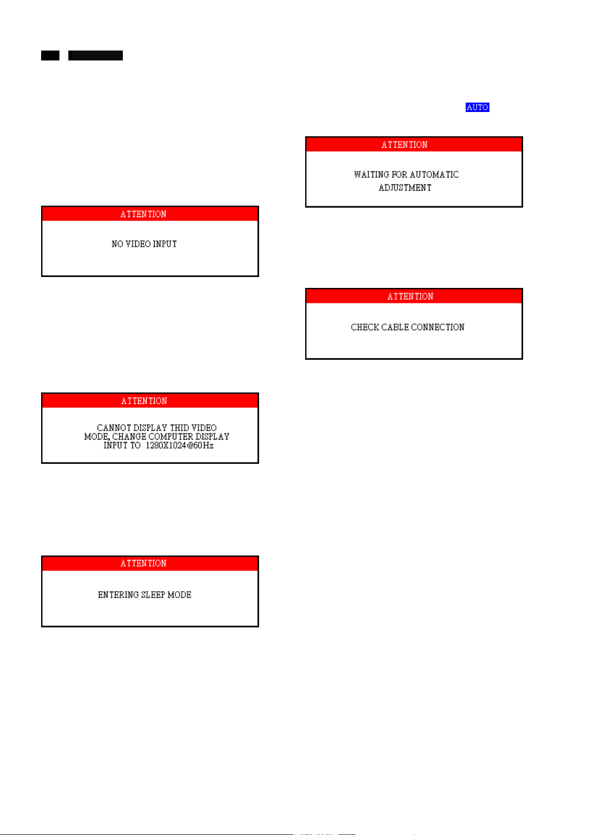
OSD Attention signals
The monitor will detect various display situation automatically.
When the monitor detects the problems, the screen will show
the different warning signals to remind you what is happen to
your monitor.
NO VIDEO INPUT
This screen appears if there is no video signal input. Please
check that the signal cable is properly connected to the video
card of PC and make sure PC is on.
CANNOT DISPLAY THIS VIDEO MODE
This screen warns when the input frequency from the computer
is not a standard video mode or out of the monitor’s scanning
range. Please change the display mode of the operating
software in the computer (i.e. Windows) to 1280x1024@60Hz
for best display results.
WAIT FOR AUTOMATIC ADJUSTMENT
This screen appears when you touch the
disappear when the monitor is properly adjusted.
CHECK CABLE CONNECTION
This message appears when a signal cable is disconnected
while computer is working.
button. It will
ENTERING SLEEP MODE
This screen appears when the monitor is about to enter the
sleep mode. Please press any key on the keyboard or click the
mouse to wake up the monitor and computer.
http://www.wjel.net
USE 1024x768 FOR BEST RESULT
This message appears at the top of the OSD window when the
video mode input is not the recommended 1280x1024. Other
modes may result in some picture distortion. Please adjust the
video mode to 1280x1024 at 60Hz for best display quality.
USE 1280x1024 FOR BEST RESULT
15 190B4 LCD
Trouble Shooting
TROUBLESHOOTING
This page presents problems that can be corrected by the user.
If the problem still exists after these possible solutions, a further
action has to be take by authorized technicians.
No Picture
(Power LED not
lit)
No Picture
(Power LED is
Amber or Yellow
In color)
Screen says
AUTO button not
working
properly
Imaging
Problems
Display position
is Incorrect
Image vibrates
on the screen
˙ Make sure the Power cable is plugged
to the wall and back of the monitor.
˙ Make sure the DC power cord has
been attached to the DC jack.
˙
First, power button in front of the
monitor should be in the OFF position,
then press it to ON position again.
˙ Make sure the computer is turned on.
˙ Make sure the signal cable is properly
connected to your computer.
˙ Check to see if the monitor cable has
bent pins.
˙
The Energy Saving Feature may be
activated.
˙
Make sure the monitor cable is properly
connected to your computer.
˙ Check to see if the monitor cable has
bent pins.
˙ Make sure the computer is turned on.
˙
The Auto Function is designed for use
on standard Macintosh or
˙ IBM-compatible PC running Microsoft
Windows.
It may not work properly if using
non-standard PCs or video card.
˙ Push the AUTO button.
Adjust the image position using the
˙
Check that the signal cable is properly
http://www.wjel.net
Horizontal Position & / or Vertical
Position in the Second Window.
connected to the graphics board or PC
Vertical flicker
appears
Horizontal flicker
appears
H-Noise No Noise
(BEFOR) (AFTER)
The screen is
too bright or too
dark
An after-image
appears
An after image
remains after the
power has been
turned off
Green, red, blue,
dark and white
dots remain on
the screen
˙ Push the AUTO button.
˙
Eliminate the vertical bars using the
Clock Adjustment in the FIRST
Windows.
˙
Push the Auto button.
˙ Eliminate the horizontal bars using the
Phase Adjustment in the First
Windows.
˙ Adjust the contrast and brightness
using the First Windows.
(The backlight of the LCD monitor has
a fixed life span. When the screen
becomes dark or begins to flicker,
please contact your dealer.)
˙ If an image remains in the screen for an
extended period of time, it may be
imprinted in the screen and leave an
after-a few hours.
˙ This is characteristic of liquid crystal
and is not caused by a malfunction or
deterioration of the liquid crystal. The
after-image will disappear after a set
amount of time.
˙ The remaining dots are normal
charactericstic of the liquid crystal used
in today’s technology.
16 190B4 LCD
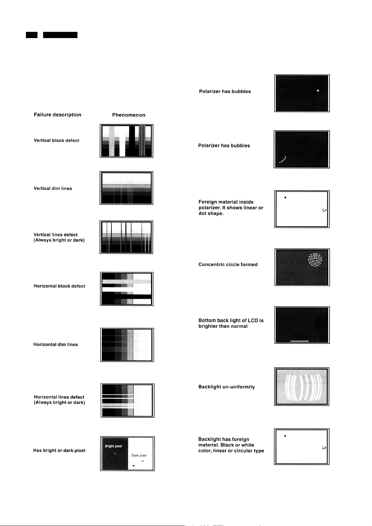
Failure Mode of LCD panel
Quick reference for failure mode of LCD panel
This page presents problems that could be made by LCD panel.
It is not necessary to repair circuit board. Simply follow the
“Mechanical instruction” on this manual to eliminate failure by
replace LCD panel or backlight tubes.
http://www.wjel.net
17 190B4 LCD
Definition of Pixel Defects
0. General
This section explains the differ ent types of pixel defects and
defines acceptable defect levels of each type. In order to qualify
for repair or replacement under warranty, the number of pixel
defects on a TFT LCD panel m ust exceed these acceptable
levels.
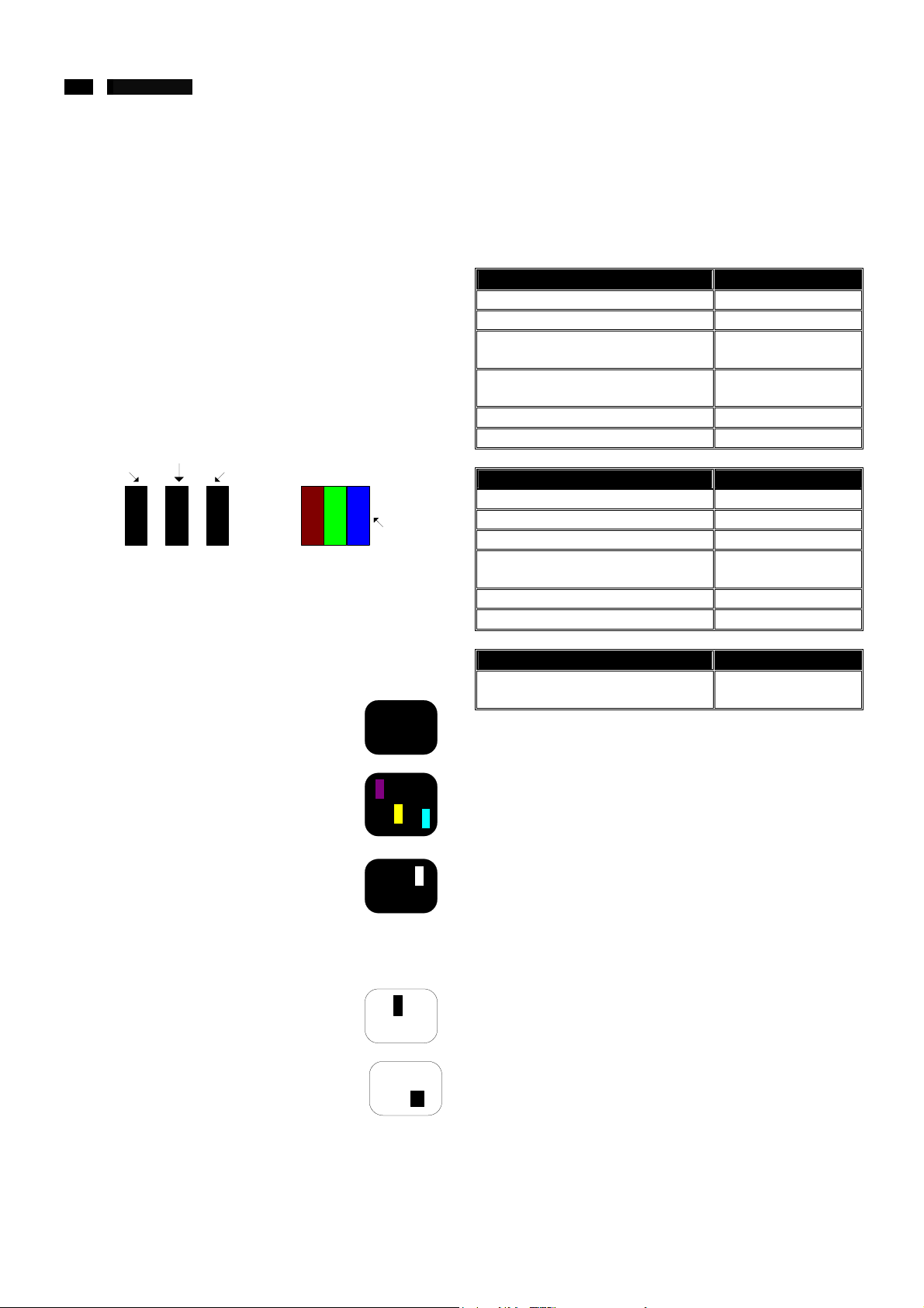
1. Definition of Pixels and Subpixels
A pixel, or picture element, is composed of three subpixels in
the primary colors of red, green and bl ue. Many pixels together
from an image. When all subpixels of a pixel are lit, the three
colored subpix els toget her app ear as a singl e white pix el. When
all are dark, the t hree colored subpi xels together appear as a
single black pixel. Other combinations of lit and dark subp ixels
appear as single pixels of other colors.
Subpixel
2. Types of Pixel Defects
Pixel and subpixel defects appear on the screen in different
ways.
Bright dot defects
Bright dot defects appear as pixels or subpixels that are always
lit or “On”. These are the types of bright dot defects:
One lit red, green or blue subpixel
Subpixel
RG
Subpixel
B
RG
B
Pixel
G
R
B
3. Pixel Defect Tolerances
In order to qual ify for repair or replacement due to pix el defects
during the warranty period, a TFT LCD panel in a Philips flat
panel monitor must have pixel or subpixel defects exceeding
the tolerances listed in the following tables.
BRIGHT DOT DEFECTS ACCEPTABLE LEVEL
1. lit subpix el 4 or fewer
2. adjacent lit subpixels 2 or fewer
3. adjacent lit subpixels
(one white pixel)
Distance between two bright o\dot
defects*
Bright dot defects within 20mm circle 3 or fewer
Total bright dot defects of all types 4 or fewer
BRIGHT DOT DEFECTS ACCEPTABLE LEVEL
1. dark subpixel 4 or fewer
2. adjacent lit dark subpixels 2 or fewer
3. adjacent li t dark subpixels 0
Distance between two black dot
defects*
Bright dot defects within 20mm circle 3 or fewer
Total bright dot defects of all types 4 or fewer
TOTAL DOT DEFECTS ACCEPTABLE LEVEL
Total bright or black dot defects of all
types
0
15mm or more
15mm or more
5 or fewer
Two adjacent lit subpixels:
- Red + Blue = Purple
- Red + Green = Yellow
- Green + Blue = Cyan (Light Blue)
Three adjacent lit subpixels
(One white pixel)
Black dot defects
Black dot defects appear as pix els or subpixels that are al ways
dark or “off”. These are the types of black dot defects:
One dark subpixel
Two or three adjacent dark subpixels
http://www.wjel.net
P
Y
C
w
18 190B4 LCD
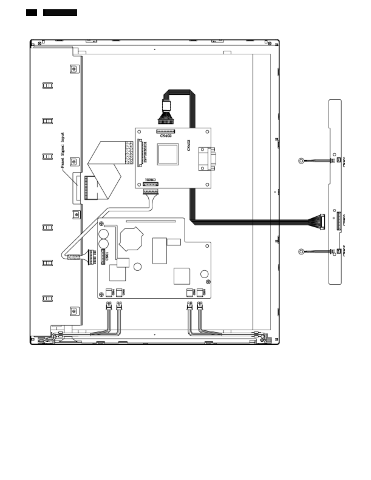
Wiring Diagram
http://www.wjel.net
19 190B4 LCD
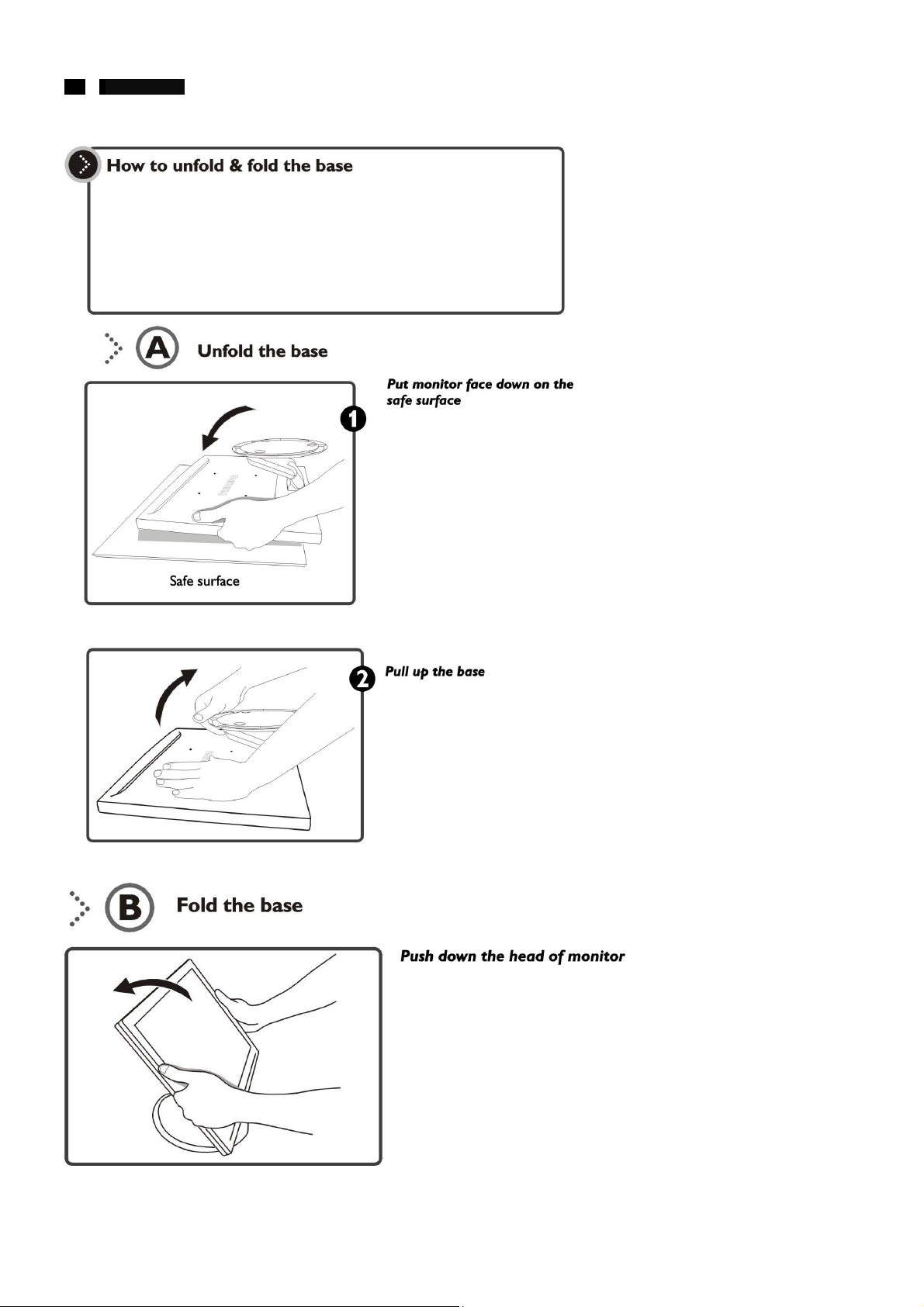
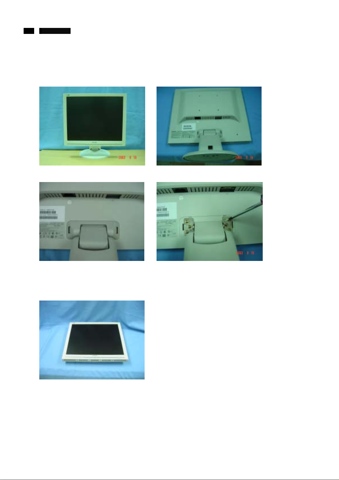
Mechanical instructions
The disassembly procedure
1. Separate the Stand
a. Pull the monitor to the highest position, then lay down the front side on the soft surface.
b. Press 2 hooks to remove Hinge cover, then remove 6 screws to se parate the stand.
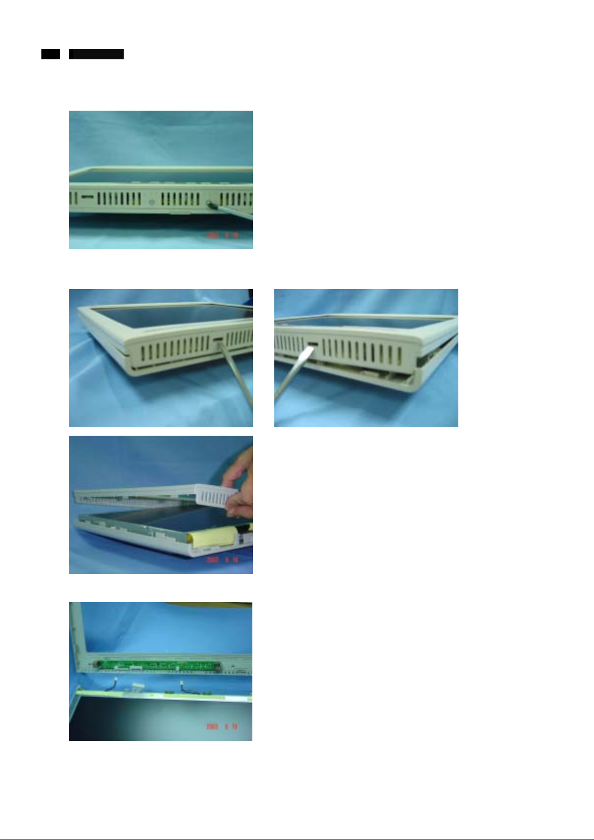
2. Separate the Front bezel
a. Turn the set upside down, let the front side upward.
http://www.wjel.net
20 190B4 LCD
Mechanical instructions
b. Remove 2 screws (on the bottom side).
c. Insert flat type of screwdriver to press 2 hooks (on the botto m side), and pull up the front bezel, then rock it left and right sides
slightly to separate it.
d. Disconnect the connect and cabl e
http://www.wjel.net
21 190B4 LCD
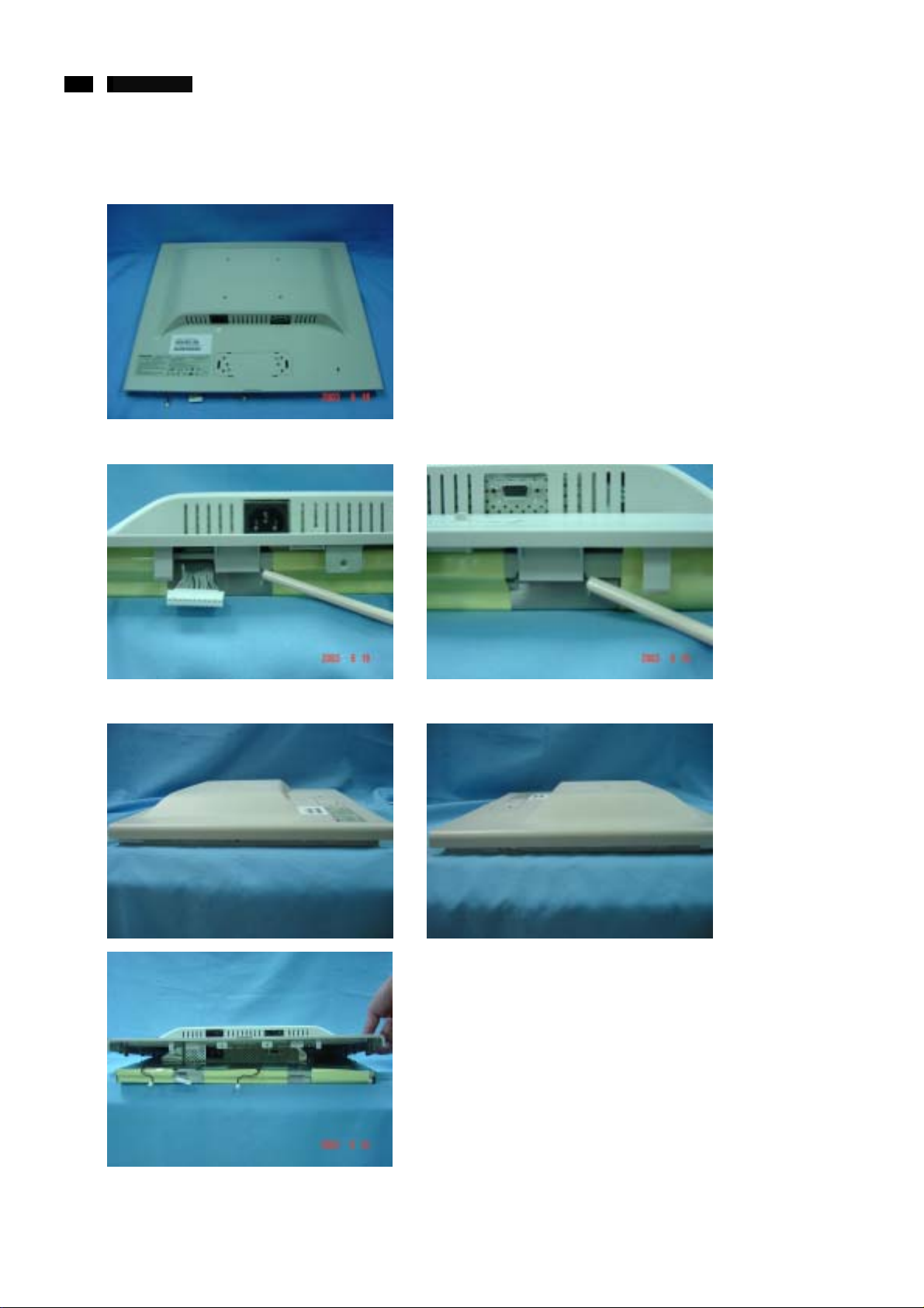
Mechanical instructions
3. Separate the back cabinet
a. Turn the set upside dow n, let the front side downward.
b. Pull leave 2 hooks (bottom the panel ) and pull up the back cabinet
c. Pull aside 4 hooks (around the Panel) and pull up the Back cabinet to separate it.
http://www.wjel.net
22 190B4 LCD
Mechanical instructions
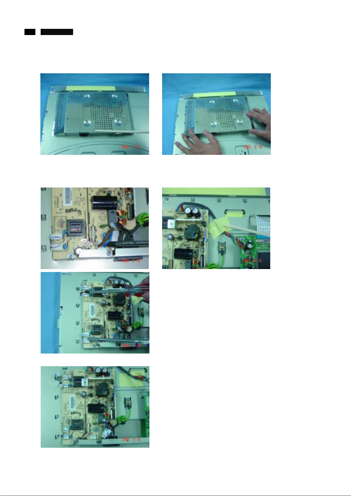
4. Separate the Shield can
Remove 1 screw then pul l down the Shield can.
5. Separate the Power & Inverter board from panel bracket
a. Disconnect the conn ect or and cable
b. Remove 4 screws
http://www.wjel.net
23 190B4 LCD
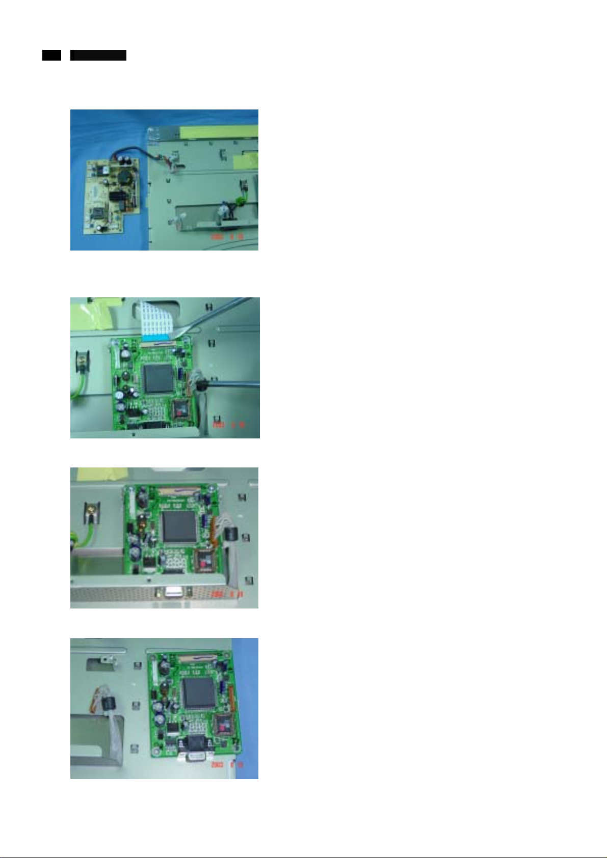
c. Separate the Power & in verter board.
6. Separate the Interface board
a. Disconnect the conn ect or and cable
Mechanical instructions
b. Remove 4 screws
c. Separate the Power & in verter board.
http://www.wjel.net
24 190B4 LCD
7. Separate the Key board
a. Remove 3 screws
b. Separate the Power & inverter board.
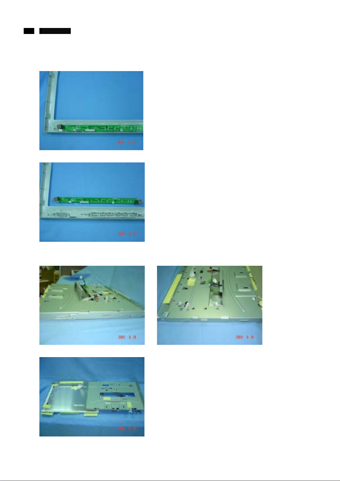
Mechanical instructions
8. Separate the Panel bracket
a. Remove 4 screws (both sides).
b. Pull down and pull up the bracket to sep arate the Panel and bracket.
http://www.wjel.net
25 190B4 LCD
Electrical instructions
0. General
When carry-o ut the el ectr ical se tt ings i n m any cases a video
signal must be applied to the monitor. A computer with:
- ATI VGA 1024 V6-1.04/PH BETA4 interface card
- PGA 1024 (4822 212 30916), Mach 8.
- PGA 1280 (4822 212 30917), Mach 32.
- ATI GPT-1600 (4822 397 10065), Mach 64 (up to 107KHz)
0.1 With normal VGA card:
If not using the ATI card during repair or alignment, The
service engine er also can use this ser vice test softw are
adapting with normal standard VGA adaptor and usi ng
standard VGA mode 640x480, 31.5KHz/60Hz (only) as
signal source.
0.2 AC/DC Measurement:
The measurements for AC waveform and DC figure is
based on 1280x1024 64KHz/60Hz resolution mode with test
pattern “32 gray scale”.
1. General points
1.1 During the test and measuring, supply a distortion free AC
mains voltage to the apparatus via an isolated transfor mer
with low internal resistance.
1.2 All measurements mentioned hereafter are carri ed out at a
normal mains voltage (90-132VAC for USA version,
195-264VAC for EUROPEAN version, or 90-264VAC for the
model with full range power supply, unless otherwise
stated.)
1.3 All voltages are to be measurement or applied with r espect
to ground, unless otherwise stated.
Note:don’t use heat-sink as ground.
1.4 The test has to be done on a complete set including LCD
panel in a room with temperature of 25+/-5 de gree C.
1.5 All values mentioned in these test instruction are only
applicable of a well aligned apparatus, with correct signal.
1.6 The letters symbols (B) and (S) placed behind the test
instruction denotes
(B):carried out 100% inspection at assembly line
(S):carried out test by sampling
1.7 The white balance (color temperature), has to be tested in
subdued lighted room.
1.8 Repetitive power on/off cycle are allowed except it should
be avoided within 6 sec.
2. Input signal
2.1 Signal type
Video :0.7Vp-p li near, positive polarity
Sync. :TTL level, separate, positive or negative polarity
Signal source:pattern generator format as attachm ent.
(table 1 to 14) Re ference g ener ator:CHROMA2200 or 2250
2.2 Input signal mode
Pre-set 15 modes
http://www.wjel.net
Factory preset video resolution
Dot rate
(MHz)
25.175 31.469 IBM VGA 10h 640 x 350 70.08 7
28.322 31.469 IBM VGA 3h 720 x 400 70.087
25.175 31.469 IBM VGA 12h 640 x 480 59.94 0
30.240 35.000 MACINTOSH 640 x 480 66.667
31.500 37.500 VESA 640 x 480 75.000
36.000 35.156 VESA 800 x 600 56.250
40.000 37.879 VESA 800 x 600 60.317
49.500 46.875 VESA 800 x 600 75.000
57.300 49.700 MACINTOSH 832 x 624 75.000
65.000 48.363 VESA 1024 x 768 60.004
78.750 60.023 VESA 1024 x 768 75.029
100 68.700 MACINTOSH 1152 x 870 75.000
108 71.810 SUN WS 1152 x 900 76.150
108 63.981 VESA 1280 x 1024 60.020
135 79.976 VESA 1280 x 1024 75.020
3. AC Adaptor
3.1 Setup the AC I/P at 90VAC, 264VAC
4. Display Adjustment
4.1 Input signals check
In factory mode, use 64 gray level and set the R, G, B sub
gain to 100%.
4.2 Display quality test
Use timing mode as described in 2.2, and use t he POPO
(pixel on pixel off) pattern to adjust the clock unt il no stripe
and adjust the phase until clear picture. Check all
pre-setting 15 modes.
4.3 Check of WHITE-D (B)
Apply a 64KHz/60Hz signal with white pattern, set
brightness control at 100%, and contrast control at 70%.
Adjust the R, G, B sub_gain, for the screen center, the 1931
CIE chromati city (X, Y ) co-ordinates shall be;
Use Minolta CA-110 for color coordinates and luminance
check.
Luminance; >160 Nits (CMO panel) in the center of the
screen.
H. freq
(KHz)
9300°K 6500°K
x (center)
y (center)
Mode Resolution
0.283 ± 0.005 0.313 ± 0.005
0.297 ± 0.005 0.329 ± 0.005
V. freq
(Hz)
 Loading...