

Page 1

Philips Telemetry System
M2600-9001C
Instructions for Use
Part Number M2600-9001C
Printed in the U.S.A. May 2002
Edition 2
Page 2

Notice
Proprietary Information
This document contains proprietary information that is protected by copyright.
All Rights Reserved. Reproduction, adaptation, or translation without prior
written permission is prohibited, except as allowed under the copyright laws.
Philips Medical Systems
3000 Minuteman Road
Andover, MA 01810-1099
(978) 687-1501
Publication number
M2600-9001C, Edition 2
Printed in USA May 2002
Warranty The information contained in this document is subject to change without notice.
Philips Medical Systems makes no warranty of any kind with regard to this
material, including, but not limited to, the implied warranties or merchantability
and fitness for a particular purpose.
Philips Medical Systems shall not be liable for errors contained herein or for
incidental or consequential damages in connection with the furnishing,
performance, or use of this material.
Trademark EASI™ is a registered trademark of Zymed, Inc.
Copyright Copyright © 2002 by Philips Medical Systems
ii
Page 3

Printing History
New editions of this document incorporate all material updated since the
previous edition. Update packages may be issued between editions and contain
replacement and additional pages to be merged by a revision date at the bottom
of the page. Pages that are rearranged due to changes on a previous page are not
considered revised.
The documentation printing date and part number indicate its current edition.
The printing date changes when a new edition is printed. (Minor corrections and
updates which are incorporated at reprint do not cause the date to change.) The
document part number changes when extensive technical changes are
incorporated.
M2600-90201, First Edition.................................................... August 1998
Printing History
Model M2604A Viridia Mainframe, revision D.01/D.02/D.03
Model M2601A Viridia Transmitter, revision A.00/A.01/A.02
Model M2605A Viridia Wave Viewer, revision A.00/A.01/A.02
Model M1403A Digital UHF Telemetry System with Option C03,
revision D.01/D.02/D.03
M2600-90201, Second Edition............................................... February 1999
Model M2604A Viridia Mainframe, revision D.01/D.02/D.03
Model M2601A Viridia Transmitter, revision A.00/A.01/A.02
Model M2605A Viridia Wave Viewer, revision A.00/A.01/A.02
Model M1403A Digital UHF Telemetry System with Option C03,
revision D.01/D.02/D.03
M2600-9001B, First Edition.................................................. February 2000
HP Telemetry System, Release B
Model M2604A Viridia Mainframe, revision D.01/D.02/D.03
Model M2601A Viridia Transmitter, revision A.00/A.01/A.02/A.03
Model M2605A Viridia Wave Viewer, revision A.00/A.01/A.02
Model M1403A Digital UHF Telemetry System with Option C03,
revision D.01/D.02/D.03
iii
Page 4

Printing History
M2600-9001C, First Edition.................................................. July 2000
Agilent Telemetry System, Release C
Model M2604A Agilent Mainframe, revision E.00
Model M2601A Agilent Transmitter, revision B.00
Model M2605A Agilent Wave Viewer, revision B.00
M2600-9001C, Second Edition.................................................. May 2002
Philips Telemetry System, Release C
Model M2604A Philips Mainframe, revision E.00
Model M2601A Philips Transmitter, revision B.00
Model M2605A Philips Wave Viewer, revision B.00
Details about the specific releases are contained in Appendix C.
iv
Page 5

About this Book
These Instructions for Use cover the use of the Philips Telemetry System
Release C with the Philips Information Center.
The Instructions for Use contain information on performing day-to-day tasks
and troubleshooting common problems as well as detailed information about all
clinical applications. It includes lists of alarm and inoperative (INOP) messages,
and configuration choices. Your purchased system may not include all of the
functionality described in this manual. When information pertains only to the
EASI
User information for the Philips Telemetry System is also contained in the
Philips Information Center On-line Help. Help focuses on how to complete basic
tasks and troubleshoot problems.
About this Book
TM
transmitters, the following EASI chest icon appears next to the title:
1
2
3
4
5
EASI
Appendix C, “System Releases” summarizes the differences between the current
version of the Philips Telemetry System and earlier system releases.
v
Page 6

About this Book
Document
Conventions
Procedures
Procedures are indicated in text by the heading Task Summary followed by the
following table:
Step Action
1
2
3
Bold Typeface
Objects of actions in procedures appear in
bold typeface. Note the following
example:
Click the
Update button.
Warnings
Warning
Warnings are information you should know to avoid injuring patients and
personnel.
Cautions
vi
Caution
Cautions are information you should know to avoid damaging your equipment
and software.
Notes
Note—Notes contain additional information on Philips Telemetry System usage.
Page 7

Contents
1. Introduction to the Philips Telemetry System . . . . . . . . . . . . . . . . . . .1-1
Indications for Use . . . . . . . . . . . . . . . . . . . . . . . . . . . . . . . . . . . . . . . . . . . . . . . . . . . . . .1-2
Condition . . . . . . . . . . . . . . . . . . . . . . . . . . . . . . . . . . . . . . . . . . . . . . . . . . . . . 1-2
Prescription Versus Over-the-Counter . . . . . . . . . . . . . . . . . . . . . . . . . . . . . . . 1-2
Part of the Body or Type of Tissue with which the Device Interacts. . . . . . . . . 1-2
Frequency of Use . . . . . . . . . . . . . . . . . . . . . . . . . . . . . . . . . . . . . . . . . . . . . . . 1-2
Physiological Purpose . . . . . . . . . . . . . . . . . . . . . . . . . . . . . . . . . . . . . . . . . . . 1-2
Patient Population . . . . . . . . . . . . . . . . . . . . . . . . . . . . . . . . . . . . . . . . . . . . . . 1-2
Intended Use . . . . . . . . . . . . . . . . . . . . . . . . . . . . . . . . . . . . . . . . . . . . . . . . . . 1-3
System Overview. . . . . . . . . . . . . . . . . . . . . . . . . . . . . . . . . . . . . . . . . . . . . . . . . . . . . . .1-4
Dual-band Operation . . . . . . . . . . . . . . . . . . . . . . . . . . . . . . . . . . . . . . . . . . . . 1-5
Transmitters. . . . . . . . . . . . . . . . . . . . . . . . . . . . . . . . . . . . . . . . . . . . . . . . . . . . . . . . . . .1-6
Philips Transmitters. . . . . . . . . . . . . . . . . . . . . . . . . . . . . . . . . . . . . . . . . . . . . . . . . .1-7
Philips Telemetry Battery Extender. . . . . . . . . . . . . . . . . . . . . . . . . . . . . . . . . . . . . .1-9
Transmitter Features. . . . . . . . . . . . . . . . . . . . . . . . . . . . . . . . . . . . . . . . . . . . . . . .1-12
Transmitter Button . . . . . . . . . . . . . . . . . . . . . . . . . . . . . . . . . . . . . . . . . . . . . 1-12
Water Resistance . . . . . . . . . . . . . . . . . . . . . . . . . . . . . . . . . . . . . . . . . . . . . . 1-12
Pouch Use . . . . . . . . . . . . . . . . . . . . . . . . . . . . . . . . . . . . . . . . . . . . . . . . . . . 1-13
Automatic Shutoff . . . . . . . . . . . . . . . . . . . . . . . . . . . . . . . . . . . . . . . . . . . . . . 1-13
Battery Information . . . . . . . . . . . . . . . . . . . . . . . . . . . . . . . . . . . . . . . . . . . . . . . . . 1-13
Use of Zinc-Air Batteries. . . . . . . . . . . . . . . . . . . . . . . . . . . . . . . . . . . . . . . . . 1-15
Maximizing Battery Life . . . . . . . . . . . . . . . . . . . . . . . . . . . . . . . . . . . . . . . . . 1-15
Disposal of Batteries. . . . . . . . . . . . . . . . . . . . . . . . . . . . . . . . . . . . . . . . . . . . 1-15
Nominal Battery Life Expectancy . . . . . . . . . . . . . . . . . . . . . . . . . . . . . . . . . . 1-16
Inserting Batteries. . . . . . . . . . . . . . . . . . . . . . . . . . . . . . . . . . . . . . . . . . . . . . 1-18
Receiver Module . . . . . . . . . . . . . . . . . . . . . . . . . . . . . . . . . . . . . . . . . . . . . . . . . . . . . .1-21
Receiver Mainframe . . . . . . . . . . . . . . . . . . . . . . . . . . . . . . . . . . . . . . . . . . . . . . . . . . .1-22
Turning the Receiver Mainframe On or Off . . . . . . . . . . . . . . . . . . . . . . . . . . 1-22
Receiver Mainframe Malfunction Light . . . . . . . . . . . . . . . . . . . . . . . . . . . . . . 1-22
Channel Frequencies . . . . . . . . . . . . . . . . . . . . . . . . . . . . . . . . . . . . . . . . . . . 1-22
Retaining Telemetry Settings . . . . . . . . . . . . . . . . . . . . . . . . . . . . . . . . . . . . . 1-22
Antenna System . . . . . . . . . . . . . . . . . . . . . . . . . . . . . . . . . . . . . . . . . . . . . . . . . . . . . .1-23
Turning Telemetry On/Off . . . . . . . . . . . . . . . . . . . . . . . . . . . . . . . . . . . . . . . . . . . . . . .1-24
Contents 1
Page 8

2. ECG Monitoring . . . . . . . . . . . . . . . . . . . . . . . . . . . . . . . . . . . . . . . . . . . 2-1
Lead Sets & Capabilities . . . . . . . . . . . . . . . . . . . . . . . . . . . . . . . . . . . . . . . . . . . . . . . . 2-2
Standard ECG Transmitter . . . . . . . . . . . . . . . . . . . . . . . . . . . . . . . . . . . . . . . . . . . 2-2
Philips EASI Transmitter . . . . . . . . . . . . . . . . . . . . . . . . . . . . . . . . . . . . . . . . . . . . . 2-4
Preparing for ECG Telemetry Monitoring. . . . . . . . . . . . . . . . . . . . . . . . . . . . . . . . . . . . 2-5
Overview . . . . . . . . . . . . . . . . . . . . . . . . . . . . . . . . . . . . . . . . . . . . . . . . . . . . . . . . . 2-5
Task Summary . . . . . . . . . . . . . . . . . . . . . . . . . . . . . . . . . . . . . . . . . . . . . . . . . . . . 2-5
EASI 12-lead Monitoring . . . . . . . . . . . . . . . . . . . . . . . . . . . . . . . . . . . . . . . . . . . . . 2-6
Making ECG Adjustments . . . . . . . . . . . . . . . . . . . . . . . . . . . . . . . . . . . . . . . . . . . . . . . 2-7
Overview . . . . . . . . . . . . . . . . . . . . . . . . . . . . . . . . . . . . . . . . . . . . . . . . . . . . . . . . . 2-7
Bandwidth . . . . . . . . . . . . . . . . . . . . . . . . . . . . . . . . . . . . . . . . . . . . . . . . . . . . . 2-7
Changing Lead/Label . . . . . . . . . . . . . . . . . . . . . . . . . . . . . . . . . . . . . . . . . . . . . . . 2-7
Adjusting Wave Size . . . . . . . . . . . . . . . . . . . . . . . . . . . . . . . . . . . . . . . . . . . . . . . . 2-7
Making Other Monitoring Adjustments . . . . . . . . . . . . . . . . . . . . . . . . . . . . . . . . . . . . . . 2-8
Turning the Transmitter Button On/Off . . . . . . . . . . . . . . . . . . . . . . . . . . . . . . . . . . 2-8
Overview . . . . . . . . . . . . . . . . . . . . . . . . . . . . . . . . . . . . . . . . . . . . . . . . . . . . . . 2-8
Task Summary . . . . . . . . . . . . . . . . . . . . . . . . . . . . . . . . . . . . . . . . . . . . . . . . . 2-8
Standby Mode . . . . . . . . . . . . . . . . . . . . . . . . . . . . . . . . . . . . . . . . . . . . . . . . . . . . . 2-9
Task Summary . . . . . . . . . . . . . . . . . . . . . . . . . . . . . . . . . . . . . . . . . . . . . . . . . 2-9
Monitoring During Leads Off . . . . . . . . . . . . . . . . . . . . . . . . . . . . . . . . . . . . . . . . . . . . 2-10
Fallback . . . . . . . . . . . . . . . . . . . . . . . . . . . . . . . . . . . . . . . . . . . . . . . . . . . . . . . . . 2-10
Multilead Analysis . . . . . . . . . . . . . . . . . . . . . . . . . . . . . . . . . . . . . . . . . . . . . . 2-10
Singlelead Analysis . . . . . . . . . . . . . . . . . . . . . . . . . . . . . . . . . . . . . . . . . . . . . 2-10
Fallback for EASI . . . . . . . . . . . . . . . . . . . . . . . . . . . . . . . . . . . . . . . . . . . . . . 2-10
Extended Monitoring . . . . . . . . . . . . . . . . . . . . . . . . . . . . . . . . . . . . . . . . . . . . . . . 2-11
Optimizing System Performance . . . . . . . . . . . . . . . . . . . . . . . . . . . . . . . . . . . . . . . . . 2-12
The Telemetry Signal . . . . . . . . . . . . . . . . . . . . . . . . . . . . . . . . . . . . . . . . . . . . . . 2-12
Frequent Signal Strength and RF INOPs . . . . . . . . . . . . . . . . . . . . . . . . . . . . . . . 2-13
Signal Strength . . . . . . . . . . . . . . . . . . . . . . . . . . . . . . . . . . . . . . . . . . . . . . . . 2-13
Radio Frequency Interference. . . . . . . . . . . . . . . . . . . . . . . . . . . . . . . . . . . . . 2-14
Muscle and Movement Artifact . . . . . . . . . . . . . . . . . . . . . . . . . . . . . . . . . . . . 2-14
ECG Alarm Summary . . . . . . . . . . . . . . . . . . . . . . . . . . . . . . . . . . . . . . . . . . . . . . . . . 2-16
Telemetry Alarm & INOP Summary . . . . . . . . . . . . . . . . . . . . . . . . . . . . . . . . . . . . . . . 2-17
Contents 2
Page 9

3. ST/AR ST Segment Monitoring . . . . . . . . . . . . . . . . . . . . . . . . . . . . . . .3-1
ST/AR ST Algorithm . . . . . . . . . . . . . . . . . . . . . . . . . . . . . . . . . . . . . . . . . . . . . . . . . . . .3-2
Intended Use. . . . . . . . . . . . . . . . . . . . . . . . . . . . . . . . . . . . . . . . . . . . . . . . . . . . . . . 3-2
Patient Population . . . . . . . . . . . . . . . . . . . . . . . . . . . . . . . . . . . . . . . . . . . . . . . . . . .3-2
The Measurement . . . . . . . . . . . . . . . . . . . . . . . . . . . . . . . . . . . . . . . . . . . . . . . . . . .3-3
How the Algorithm Works . . . . . . . . . . . . . . . . . . . . . . . . . . . . . . . . . . . . . . . . . . . . .3-4
Displayed ST Data . . . . . . . . . . . . . . . . . . . . . . . . . . . . . . . . . . . . . . . . . . . . . . . . . .3-4
EASI ST Analysis . . . . . . . . . . . . . . . . . . . . . . . . . . . . . . . . . . . . . . . . . . . . . . . . . . . 3-4
Adjusting Measurement Points . . . . . . . . . . . . . . . . . . . . . . . . . . . . . . . . . . . . . . . . . . . .3-5
Overview . . . . . . . . . . . . . . . . . . . . . . . . . . . . . . . . . . . . . . . . . . . . . . . . . . . . . . . . . .3-5
Task Summary . . . . . . . . . . . . . . . . . . . . . . . . . . . . . . . . . . . . . . . . . . . . . . . . . . . . . 3-5
Establishing ST Reference Beats (Baseline). . . . . . . . . . . . . . . . . . . . . . . . . . . . . . . . . .3-7
Turning ST On/Off . . . . . . . . . . . . . . . . . . . . . . . . . . . . . . . . . . . . . . . . . . . . . . . . . . . . . .3-7
Overview . . . . . . . . . . . . . . . . . . . . . . . . . . . . . . . . . . . . . . . . . . . . . . . . . . . . . . . . . .3-7
Task Summary . . . . . . . . . . . . . . . . . . . . . . . . . . . . . . . . . . . . . . . . . . . . . . . . . . . . . 3-7
ST Alarms . . . . . . . . . . . . . . . . . . . . . . . . . . . . . . . . . . . . . . . . . . . . . . . . . . . . . . . . . . . .3-8
Overview . . . . . . . . . . . . . . . . . . . . . . . . . . . . . . . . . . . . . . . . . . . . . . . . . . . . . . . . . .3-8
ST Alarm Adjustments . . . . . . . . . . . . . . . . . . . . . . . . . . . . . . . . . . . . . . . . . . . . . . .3-9
ST Alarm and INOP Summary . . . . . . . . . . . . . . . . . . . . . . . . . . . . . . . . . . . . . . . .3-10
4. SpO2 Monitoring . . . . . . . . . . . . . . . . . . . . . . . . . . . . . . . . . . . . . . . . . . .4-1
Overview . . . . . . . . . . . . . . . . . . . . . . . . . . . . . . . . . . . . . . . . . . . . . . . . . . . . . . . . . . . . .4-2
Preparing for Telemetry SpO
Overview . . . . . . . . . . . . . . . . . . . . . . . . . . . . . . . . . . . . . . . . . . . . . . . . . . . . . . . . . .4-4
Task Summary . . . . . . . . . . . . . . . . . . . . . . . . . . . . . . . . . . . . . . . . . . . . . . . . . . . . . 4-4
Making SpO
Measurements . . . . . . . . . . . . . . . . . . . . . . . . . . . . . . . . . . . . . . . . . . . . .4-6
2
Automatic Measurements . . . . . . . . . . . . . . . . . . . . . . . . . . . . . . . . . . . . . . . . . . . . .4-6
Manual Measurements . . . . . . . . . . . . . . . . . . . . . . . . . . . . . . . . . . . . . . . . . . . . . . .4-6
Task Summary . . . . . . . . . . . . . . . . . . . . . . . . . . . . . . . . . . . . . . . . . . . . . . . . . 4-6
Measurement Limitations . . . . . . . . . . . . . . . . . . . . . . . . . . . . . . . . . . . . . . . . . . . . . . . . 4-8
SpO
Transducers. . . . . . . . . . . . . . . . . . . . . . . . . . . . . . . . . . . . . . . . . . . . . . . . . . . . . .4-9
2
Disposable Transducers . . . . . . . . . . . . . . . . . . . . . . . . . . . . . . . . . . . . . . . . . . . . . .4-9
Reusable Transducers . . . . . . . . . . . . . . . . . . . . . . . . . . . . . . . . . . . . . . . . . . . . . . . 4-9
Selecting the Appropriate Transducer . . . . . . . . . . . . . . . . . . . . . . . . . . . . . . . . . . . . . .4-10
Applying the Transducer . . . . . . . . . . . . . . . . . . . . . . . . . . . . . . . . . . . . . . . . . . . . . . . .4-11
Overview . . . . . . . . . . . . . . . . . . . . . . . . . . . . . . . . . . . . . . . . . . . . . . . . . . . . . . . . .4-11
Warnings . . . . . . . . . . . . . . . . . . . . . . . . . . . . . . . . . . . . . . . . . . . . . . . . . . . . . . . . . 4-12
Adult Finger Transducer (M1191A). . . . . . . . . . . . . . . . . . . . . . . . . . . . . . . . . . . . .4-13
Small Adult/Pediatric Finger Transducer (M1192A) . . . . . . . . . . . . . . . . . . . . . . . .4-14
Ear Clip Transducer (M1194A) . . . . . . . . . . . . . . . . . . . . . . . . . . . . . . . . . . . . . . . .4-15
Disposable Transducers . . . . . . . . . . . . . . . . . . . . . . . . . . . . . . . . . . . . . . . . . . . . .4-15
Optimizing Transducer Performance. . . . . . . . . . . . . . . . . . . . . . . . . . . . . . . . . . . . . . .4-16
Monitoring . . . . . . . . . . . . . . . . . . . . . . . . . . . . . . . . . . . .4-4
2
Contents 3
Page 10

Turning the SpO
Parameter On/Off . . . . . . . . . . . . . . . . . . . . . . . . . . . . . . . . . . . . . . 4-17
2
Overview . . . . . . . . . . . . . . . . . . . . . . . . . . . . . . . . . . . . . . . . . . . . . . . . . . . . . . . . 4-17
SpO
Parameter Auto ON . . . . . . . . . . . . . . . . . . . . . . . . . . . . . . . . . . . . . . . . . . . 4-17
2
Task Summary . . . . . . . . . . . . . . . . . . . . . . . . . . . . . . . . . . . . . . . . . . . . . . . . . . . 4-18
Turning SpO
Alarms On/Off . . . . . . . . . . . . . . . . . . . . . . . . . . . . . . . . . . . . . . . . . . . . 4-19
2
Overview . . . . . . . . . . . . . . . . . . . . . . . . . . . . . . . . . . . . . . . . . . . . . . . . . . . . . . . . 4-19
Task Summary . . . . . . . . . . . . . . . . . . . . . . . . . . . . . . . . . . . . . . . . . . . . . . . . . . . 4-19
Turning the Pulse Parameter On/Off . . . . . . . . . . . . . . . . . . . . . . . . . . . . . . . . . . . . . . 4-19
Overview . . . . . . . . . . . . . . . . . . . . . . . . . . . . . . . . . . . . . . . . . . . . . . . . . . . . . . . . 4-19
Task Summary . . . . . . . . . . . . . . . . . . . . . . . . . . . . . . . . . . . . . . . . . . . . . . . . . . . 4-19
SpO
Alarm and INOP Summary. . . . . . . . . . . . . . . . . . . . . . . . . . . . . . . . . . . . . . . . . 4-20
2
5. Telemetry System Cleaning. . . . . . . . . . . . . . . . . . . . . . . . . . . . . . . . . . 5-1
Cleaning and Disinfection . . . . . . . . . . . . . . . . . . . . . . . . . . . . . . . . . . . . . . . . . . . . . . . 5-2
Cleaning the Receiver Mainframe . . . . . . . . . . . . . . . . . . . . . . . . . . . . . . . . . . . . . . . . . 5-3
Cleaning the Transmitter & Battery Extender . . . . . . . . . . . . . . . . . . . . . . . . . . . . . . . . 5-4
Wiping the Transmitter Exterior . . . . . . . . . . . . . . . . . . . . . . . . . . . . . . . . . . . . . . . . 5-4
Task Summary . . . . . . . . . . . . . . . . . . . . . . . . . . . . . . . . . . . . . . . . . . . . . . . . . 5-4
Wiping the Battery Compartment . . . . . . . . . . . . . . . . . . . . . . . . . . . . . . . . . . . . . . 5-5
Task Summary . . . . . . . . . . . . . . . . . . . . . . . . . . . . . . . . . . . . . . . . . . . . . . . . . 5-5
Wiping the Battery Extender . . . . . . . . . . . . . . . . . . . . . . . . . . . . . . . . . . . . . . . . . . 5-6
Task Summary . . . . . . . . . . . . . . . . . . . . . . . . . . . . . . . . . . . . . . . . . . . . . . . . . 5-6
Soaking the Transmitter & Cradle . . . . . . . . . . . . . . . . . . . . . . . . . . . . . . . . . . . . . . 5-7
Task Summary . . . . . . . . . . . . . . . . . . . . . . . . . . . . . . . . . . . . . . . . . . . . . . . . . 5-7
Cross-infection Prevention for the Transmitter & Battery Extender . . . . . . . . . . . . . . . . 5-8
Cross-infection Prevention and Aeration . . . . . . . . . . . . . . . . . . . . . . . . . . . . . . . . . 5-9
Equipment and Materials . . . . . . . . . . . . . . . . . . . . . . . . . . . . . . . . . . . . . . . . . 5-9
Cross-infection Process . . . . . . . . . . . . . . . . . . . . . . . . . . . . . . . . . . . . . . . . . 5-10
Task Summary . . . . . . . . . . . . . . . . . . . . . . . . . . . . . . . . . . . . . . . . . . . . . . . . 5-10
Aeration Procedure . . . . . . . . . . . . . . . . . . . . . . . . . . . . . . . . . . . . . . . . . . . . . 5-12
Task Summary . . . . . . . . . . . . . . . . . . . . . . . . . . . . . . . . . . . . . . . . . . . . . . . . 5-12
References . . . . . . . . . . . . . . . . . . . . . . . . . . . . . . . . . . . . . . . . . . . . . . . . . . . 5-12
Making Sure the Equipment Works . . . . . . . . . . . . . . . . . . . . . . . . . . . . . . . . . . . . 5-13
Task Summary . . . . . . . . . . . . . . . . . . . . . . . . . . . . . . . . . . . . . . . . . . . . . . . . 5-13
Cleaning the Hewlett-Packard 200LX Palmtop Computer . . . . . . . . . . . . . . . . . . . . . . 5-15
Cleaning ECG Patient Cables and Leads . . . . . . . . . . . . . . . . . . . . . . . . . . . . . . . . . . 5-16
Cleaning . . . . . . . . . . . . . . . . . . . . . . . . . . . . . . . . . . . . . . . . . . . . . . . . . . . . . . . . 5-16
Disinfecting . . . . . . . . . . . . . . . . . . . . . . . . . . . . . . . . . . . . . . . . . . . . . . . . . . . . . . 5-17
Sterilizing . . . . . . . . . . . . . . . . . . . . . . . . . . . . . . . . . . . . . . . . . . . . . . . . . . . . . . . . 5-17
Cleaning SpO
Philips Adapter Cable . . . . . . . . . . . . . . . . . . . . . . . . . . . . . . . . . . . . . . . . . . . . . . 5-18
Philips Reusable Transducers. . . . . . . . . . . . . . . . . . . . . . . . . . . . . . . . . . . . . . . . 5-19
Adapter Cable & Transducers. . . . . . . . . . . . . . . . . . . . . . . . . . . . . . . 5-18
2
Contents 4
Page 11

6. Telemetry System Configuration. . . . . . . . . . . . . . . . . . . . . . . . . . . . . .6-1
About Configuration . . . . . . . . . . . . . . . . . . . . . . . . . . . . . . . . . . . . . . . . . . . . . . . . . . . . .6-2
Configuration Settings . . . . . . . . . . . . . . . . . . . . . . . . . . . . . . . . . . . . . . . . . . . . . . . . . . .6-3
M2604A Mainframe. . . . . . . . . . . . . . . . . . . . . . . . . . . . . . . . . . . . . . . . . . . . . . . . . .6-3
Philips M2601X Series Transmitter. . . . . . . . . . . . . . . . . . . . . . . . . . . . . . . . . . . . . .6-5
Changing the Configuration . . . . . . . . . . . . . . . . . . . . . . . . . . . . . . . . . . . . . . . . . . . . . . .6-6
Configuring Replacement Philips Transmitters . . . . . . . . . . . . . . . . . . . . . . . . . . . . . 6-6
Task Summary . . . . . . . . . . . . . . . . . . . . . . . . . . . . . . . . . . . . . . . . . . . . . . . . . 6-7
Changing Frequencies for Philips Transmitters . . . . . . . . . . . . . . . . . . . . . . . . . . . .6-8
Task Summary . . . . . . . . . . . . . . . . . . . . . . . . . . . . . . . . . . . . . . . . . . . . . . . . . 6-8
7. System Safety and Specifications. . . . . . . . . . . . . . . . . . . . . . . . . . . . .7-1
Safety Requirements . . . . . . . . . . . . . . . . . . . . . . . . . . . . . . . . . . . . . . . . . . . . . . . . . . . .7-2
Philips Telemetry System Warnings . . . . . . . . . . . . . . . . . . . . . . . . . . . . . . . . . . . . . . . .7-3
Electromagnetic Compatibility . . . . . . . . . . . . . . . . . . . . . . . . . . . . . . . . . . . . . . . . . . . . .7-4
M2600A Philips Telemetry System Testing . . . . . . . . . . . . . . . . . . . . . . . . . . . . . . .7-4
EN61000-4-3 . . . . . . . . . . . . . . . . . . . . . . . . . . . . . . . . . . . . . . . . . . . . . . . . . . 7-4
IEC 801-4 . . . . . . . . . . . . . . . . . . . . . . . . . . . . . . . . . . . . . . . . . . . . . . . . . . . . . 7-4
Philips Telemetry System Characteristics. . . . . . . . . . . . . . . . . . . . . . . . . . . . . . . . . 7-5
Avoiding EMI . . . . . . . . . . . . . . . . . . . . . . . . . . . . . . . . . . . . . . . . . . . . . . . . . . . . . . .7-5
FCC Compliance (USA only) . . . . . . . . . . . . . . . . . . . . . . . . . . . . . . . . . . . . . . . . . .7-5
Canadian Radio Equipment Compliance (Canada Only) . . . . . . . . . . . . . . . . . . . . .7-6
System Symbols . . . . . . . . . . . . . . . . . . . . . . . . . . . . . . . . . . . . . . . . . . . . . . . . . . . . . . .7-7
Type CF Defibrillation Proof . . . . . . . . . . . . . . . . . . . . . . . . . . . . . . . . . . . . . . . . . .7-12
Installation and Maintenance Safety . . . . . . . . . . . . . . . . . . . . . . . . . . . . . . . . . . . . . . . 7-13
Installation . . . . . . . . . . . . . . . . . . . . . . . . . . . . . . . . . . . . . . . . . . . . . . . . . . . . . . . .7-13
Environment . . . . . . . . . . . . . . . . . . . . . . . . . . . . . . . . . . . . . . . . . . . . . . . . . . 7-13
Grounding . . . . . . . . . . . . . . . . . . . . . . . . . . . . . . . . . . . . . . . . . . . . . . . . . . . . 7-13
Condensation . . . . . . . . . . . . . . . . . . . . . . . . . . . . . . . . . . . . . . . . . . . . . . . . . 7-14
Maintenance . . . . . . . . . . . . . . . . . . . . . . . . . . . . . . . . . . . . . . . . . . . . . . . . . . . . . .7-14
Receiver Mainframe . . . . . . . . . . . . . . . . . . . . . . . . . . . . . . . . . . . . . . . . . . . 7-15
Antenna Amplifiers . . . . . . . . . . . . . . . . . . . . . . . . . . . . . . . . . . . . . . . . . . . . . 7-16
Patient Monitor/Holter Interface Option . . . . . . . . . . . . . . . . . . . . . . . . . . . . . 7-16
Preventive Maintenance . . . . . . . . . . . . . . . . . . . . . . . . . . . . . . . . . . . . . . . . . . . . .7-16
End of Life . . . . . . . . . . . . . . . . . . . . . . . . . . . . . . . . . . . . . . . . . . . . . . . . . . . . . . . .7-17
Additional Safety Information. . . . . . . . . . . . . . . . . . . . . . . . . . . . . . . . . . . . . . . . . . . . .7-18
Software Hazard Prevention. . . . . . . . . . . . . . . . . . . . . . . . . . . . . . . . . . . . . . 7-18
System Specifications . . . . . . . . . . . . . . . . . . . . . . . . . . . . . . . . . . . . . . . . . . . . . . . . . .7-19
System Classification . . . . . . . . . . . . . . . . . . . . . . . . . . . . . . . . . . . . . . . . . . . . . . .7-19
Environmental Conditions . . . . . . . . . . . . . . . . . . . . . . . . . . . . . . . . . . . . . . . . . . . .7-20
Contents 5
Page 12

For Philips Transmitters . . . . . . . . . . . . . . . . . . . . . . . . . . . . . . . . . . . . . . . . . 7-20
For Hewlett-Packard 200LX Palmtop Computer . . . . . . . . . . . . . . . . . . . . . . . 7-20
For Reusable Pulse Oximetry Sensors . . . . . . . . . . . . . . . . . . . . . . . . . . . . . . 7-21
Electrical Power Specifications . . . . . . . . . . . . . . . . . . . . . . . . . . . . . . . . . . . . . . . 7-22
M2601A Transmitters . . . . . . . . . . . . . . . . . . . . . . . . . . . . . . . . . . . . . . . . . . . 7-22
M2604A Receiver Mainframe . . . . . . . . . . . . . . . . . . . . . . . . . . . . . . . . . . . . . 7-23
M2604A Receiver Main Frame . . . . . . . . . . . . . . . . . . . . . . . . . . . . . . . . . . . . 7-24
M2603A Receiver Module . . . . . . . . . . . . . . . . . . . . . . . . . . . . . . . . . . . . . . . . 7-25
M2611A Battery Extender . . . . . . . . . . . . . . . . . . . . . . . . . . . . . . . . . . . . . . . . 7-25
Patient Monitor Holter Recorder Interface (Analog Output) Option J01 . . . . . 7-25
Antenna System Specifications . . . . . . . . . . . . . . . . . . . . . . . . . . . . . . . . . . . . . . . 7-27
M1406A Line Amplifier . . . . . . . . . . . . . . . . . . . . . . . . . . . . . . . . . . . . . . . . . . 7-27
M1407A Multiple Unit Power Supply. . . . . . . . . . . . . . . . . . . . . . . . . . . . . . . . 7-27
M1408A Active Antenna Combiner . . . . . . . . . . . . . . . . . . . . . . . . . . . . . . . . . 7-28
M2606A Line Amplifier . . . . . . . . . . . . . . . . . . . . . . . . . . . . . . . . . . . . . . . . . . 7-28
M2607A Multiple Unit Power Supply. . . . . . . . . . . . . . . . . . . . . . . . . . . . . . . . 7-29
M2608A Active Antenna/Combiner . . . . . . . . . . . . . . . . . . . . . . . . . . . . . . . . . 7-29
M2609A Attenuator . . . . . . . . . . . . . . . . . . . . . . . . . . . . . . . . . . . . . . . . . . . . . 7-30
M2612A Bandpass Filter . . . . . . . . . . . . . . . . . . . . . . . . . . . . . . . . . . . . . . . . . 7-30
M2616A External Frequency Converter . . . . . . . . . . . . . . . . . . . . . . . . . . . . . 7-31
Measurement Specifications . . . . . . . . . . . . . . . . . . . . . . . . . . . . . . . . . . . . . . . . . 7-31
ECG . . . . . . . . . . . . . . . . . . . . . . . . . . . . . . . . . . . . . . . . . . . . . . . . . . . . . . . . 7-31
SpO
. . . . . . . . . . . . . . . . . . . . . . . . . . . . . . . . . . . . . . . . . . . . . . . . . . . . . . . . 7-32
2
Pulse Rate. . . . . . . . . . . . . . . . . . . . . . . . . . . . . . . . . . . . . . . . . . . . . . . . . . . . 7-32
Contents 6
Page 13

APPENDICES
A. Optional Patient Monitor/Holter Interface (Analog Output) . . . . . . . A-1
Overview . . . . . . . . . . . . . . . . . . . . . . . . . . . . . . . . . . . . . . . . . . . . . . . . . . . . . . . . . . . . A-2
Correct Labeling . . . . . . . . . . . . . . . . . . . . . . . . . . . . . . . . . . . . . . . . . . . . . . . . . . . A-2
Analog Output Bedside Monitor Cables . . . . . . . . . . . . . . . . . . . . . . . . . . . . . . . . . . . . A-3
Lead Placement and Selection . . . . . . . . . . . . . . . . . . . . . . . . . . . . . . . . . . . . . . . . . . . A-5
Using Non-standard Lead Placement . . . . . . . . . . . . . . . . . . . . . . . . . . . . . . . . . . . A-5
Controls for Telemetry Setup. . . . . . . . . . . . . . . . . . . . . . . . . . . . . . . . . . . . . . . . . . . . . A-6
Functionality with Paced Waves . . . . . . . . . . . . . . . . . . . . . . . . . . . . . . . . . . . . . . . . . . A-6
Inoperative (INOP) Conditions. . . . . . . . . . . . . . . . . . . . . . . . . . . . . . . . . . . . . . . . . . . . A-7
Holter Interface . . . . . . . . . . . . . . . . . . . . . . . . . . . . . . . . . . . . . . . . . . . . . . . . . . . . . . . A-8
B. Accessories and Ordering Information . . . . . . . . . . . . . . . . . . . . . . . B-1
C. System Releases . . . . . . . . . . . . . . . . . . . . . . . . . . . . . . . . . . . . . . . . . C-1
Release Features and Upgrade Notes . . . . . . . . . . . . . . . . . . . . . . . . . . . . . . . . . . . . . C-1
Release C Enhancement Details. . . . . . . . . . . . . . . . . . . . . . . . . . . . . . . . . . . . . . . . . . C-4
EASI 12-lead Monitoring . . . . . . . . . . . . . . . . . . . . . . . . . . . . . . . . . . . . . . . . . . . . . C-4
What You Need to Know . . . . . . . . . . . . . . . . . . . . . . . . . . . . . . . . . . . . . . . . . C-4
During INOPs . . . . . . . . . . . . . . . . . . . . . . . . . . . . . . . . . . . . . . . . . . . . . . . . . . . . . C-5
EASI Electrode Placement with a5-wire leadset for 12-lead ECG . . . . . . . . . . C-6
Viewing EASI Leads . . . . . . . . . . . . . . . . . . . . . . . . . . . . . . . . . . . . . . . . . . . . . . . . C-7
Task Summary . . . . . . . . . . . . . . . . . . . . . . . . . . . . . . . . . . . . . . . . . . . . . . . . . C-7
Additions to Hard INOP Messages at Central. . . . . . . . . . . . . . . . . . . . . . . . . . . . . C-8
WaveViewer INOP Change. . . . . . . . . . . . . . . . . . . . . . . . . . . . . . . . . . . . . . . . . . . C-8
ST Segment Monitoring with EASI . . . . . . . . . . . . . . . . . . . . . . . . . . . . . . . . . . . . . C-9
Multilead Alarms with EASI . . . . . . . . . . . . . . . . . . . . . . . . . . . . . . . . . . . . . . . C-9
SpO
Parameter Auto ON . . . . . . . . . . . . . . . . . . . . . . . . . . . . . . . . . . . . . . . . . . . . . . C-10
2
Other Changes . . . . . . . . . . . . . . . . . . . . . . . . . . . . . . . . . . . . . . . . . . . . . . . . . . . C-10
D. Wave Viewer Basics . . . . . . . . . . . . . . . . . . . . . . . . . . . . . . . . . . . . . . . D-1
Indications for Use . . . . . . . . . . . . . . . . . . . . . . . . . . . . . . . . . . . . . . . . . . . . . . . . . . . . . D-2
Condition . . . . . . . . . . . . . . . . . . . . . . . . . . . . . . . . . . . . . . . . . . . . . . . . . . . . . D-2
Prescription Versus Over-the-Counter . . . . . . . . . . . . . . . . . . . . . . . . . . . . . . . D-2
Part of the Body or Type of Tissue with Which the Device Interacts . . . . . . . . D-2
Frequency of Use . . . . . . . . . . . . . . . . . . . . . . . . . . . . . . . . . . . . . . . . . . . . . . . D-2
Physiological Purpose . . . . . . . . . . . . . . . . . . . . . . . . . . . . . . . . . . . . . . . . . . . D-2
Patient Population . . . . . . . . . . . . . . . . . . . . . . . . . . . . . . . . . . . . . . . . . . . . . . D-2
Intended Use . . . . . . . . . . . . . . . . . . . . . . . . . . . . . . . . . . . . . . . . . . . . . . . . . . D-3
Contents 7
Page 14

Introducing the Wave Viewer . . . . . . . . . . . . . . . . . . . . . . . . . . . . . . . . . . . . . . . . . . . . . D-5
Environmental Limits. . . . . . . . . . . . . . . . . . . . . . . . . . . . . . . . . . . . . . . . . . . . . D-6
Installing the Wave Viewer. . . . . . . . . . . . . . . . . . . . . . . . . . . . . . . . . . . . . . . . . . . . . . . D-7
Overview . . . . . . . . . . . . . . . . . . . . . . . . . . . . . . . . . . . . . . . . . . . . . . . . . . . . . . . . . D-7
Task Summary . . . . . . . . . . . . . . . . . . . . . . . . . . . . . . . . . . . . . . . . . . . . . . . . . . . . D-7
Connecting to the Transmitter . . . . . . . . . . . . . . . . . . . . . . . . . . . . . . . . . . . . . . . . . . . . D-9
Overview . . . . . . . . . . . . . . . . . . . . . . . . . . . . . . . . . . . . . . . . . . . . . . . . . . . . . . . . . D-9
Connecting Directly . . . . . . . . . . . . . . . . . . . . . . . . . . . . . . . . . . . . . . . . . . . . . . . . D-10
Connecting with a Light Pipe . . . . . . . . . . . . . . . . . . . . . . . . . . . . . . . . . . . . . . . . . D-11
Battery Information. . . . . . . . . . . . . . . . . . . . . . . . . . . . . . . . . . . . . . . . . . . . . . . . . . . . D-13
Battery Types and Battery Life . . . . . . . . . . . . . . . . . . . . . . . . . . . . . . . . . . . . . . . D-13
Battery Status . . . . . . . . . . . . . . . . . . . . . . . . . . . . . . . . . . . . . . . . . . . . . . . . . . . . D-14
When to Replace Palmtop Batteries . . . . . . . . . . . . . . . . . . . . . . . . . . . . . . . . . . . D-14
Removing and Installing Palmtop Batteries . . . . . . . . . . . . . . . . . . . . . . . . . . . . . . D-14
Changing the Main Batteries . . . . . . . . . . . . . . . . . . . . . . . . . . . . . . . . . . . . . . D-15
Changing the Backup Battery . . . . . . . . . . . . . . . . . . . . . . . . . . . . . . . . . . . . . . . . D-16
Software License Agreement. . . . . . . . . . . . . . . . . . . . . . . . . . . . . . . . . . . . . . . . . . . . D-17
Philips Medical Systems Software License Terms . . . . . . . . . . . . . . . . . . . . . . . . D-17
E. Wave Viewer Instructions for Use . . . . . . . . . . . . . . . . . . . . . . . . . . . E-1
Wave Viewer Controls . . . . . . . . . . . . . . . . . . . . . . . . . . . . . . . . . . . . . . . . . . . . . . . . . . E-2
Keys. . . . . . . . . . . . . . . . . . . . . . . . . . . . . . . . . . . . . . . . . . . . . . . . . . . . . . . . . . . . . E-2
Main Screen . . . . . . . . . . . . . . . . . . . . . . . . . . . . . . . . . . . . . . . . . . . . . . . . . . . . . . E-2
Using the Wave Viewer . . . . . . . . . . . . . . . . . . . . . . . . . . . . . . . . . . . . . . . . . . . . . . . . . E-3
Overview . . . . . . . . . . . . . . . . . . . . . . . . . . . . . . . . . . . . . . . . . . . . . . . . . . . . . . . . . E-3
Checking ECG Signal Quality . . . . . . . . . . . . . . . . . . . . . . . . . . . . . . . . . . . . . . . . . E-4
Task Summary . . . . . . . . . . . . . . . . . . . . . . . . . . . . . . . . . . . . . . . . . . . . . . . . . E-4
Viewing Other Standard ECG Leads. . . . . . . . . . . . . . . . . . . . . . . . . . . . . . . . . . . . E-5
Task Summary . . . . . . . . . . . . . . . . . . . . . . . . . . . . . . . . . . . . . . . . . . . . . . . . . E-5
Viewing EASI Leads . . . . . . . . . . . . . . . . . . . . . . . . . . . . . . . . . . . . . . . . . . . . . . . . E-6
Task Summary . . . . . . . . . . . . . . . . . . . . . . . . . . . . . . . . . . . . . . . . . . . . . . . . . E-6
Changing the Lead (Standard ECG only) . . . . . . . . . . . . . . . . . . . . . . . . . . . . . . . . E-7
Task Summary . . . . . . . . . . . . . . . . . . . . . . . . . . . . . . . . . . . . . . . . . . . . . . . . . E-7
Adjusting ECG Size . . . . . . . . . . . . . . . . . . . . . . . . . . . . . . . . . . . . . . . . . . . . . . . . . E-7
Task Summary . . . . . . . . . . . . . . . . . . . . . . . . . . . . . . . . . . . . . . . . . . . . . . . . . E-7
Estimating the Heart Rate . . . . . . . . . . . . . . . . . . . . . . . . . . . . . . . . . . . . . . . . . . . . E-8
Task Summary . . . . . . . . . . . . . . . . . . . . . . . . . . . . . . . . . . . . . . . . . . . . . . . . . E-8
Checking SpO
Task Summary . . . . . . . . . . . . . . . . . . . . . . . . . . . . . . . . . . . . . . . . . . . . . . . . . E-9
Changing the SpO
Task Summary . . . . . . . . . . . . . . . . . . . . . . . . . . . . . . . . . . . . . . . . . . . . . . . . E-10
Making a STAT SpO
Signal Quality. . . . . . . . . . . . . . . . . . . . . . . . . . . . . . . . . . . . . . . . . E-9
2
Sample Rate . . . . . . . . . . . . . . . . . . . . . . . . . . . . . . . . . . . . . E-10
2
. . . . . . . . . . . . . . . . . . . . . . . . . . . . . . . . . . . . . . . . . . . . . . E-11
2
Contents 8
Page 15

Task Summary . . . . . . . . . . . . . . . . . . . . . . . . . . . . . . . . . . . . . . . . . . . . . . . . E-11
Using Help. . . . . . . . . . . . . . . . . . . . . . . . . . . . . . . . . . . . . . . . . . . . . . . . . . . . . . . E-12
Task Summary . . . . . . . . . . . . . . . . . . . . . . . . . . . . . . . . . . . . . . . . . . . . . . . . E-12
Deactivatingthe Wave Viewer . . . . . . . . . . . . . . . . . . . . . . . . . . . . . . . . . . . . . . . . E-13
Task Summary . . . . . . . . . . . . . . . . . . . . . . . . . . . . . . . . . . . . . . . . . . . . . . . . E-13
Power Save Mode. . . . . . . . . . . . . . . . . . . . . . . . . . . . . . . . . . . . . . . . . . . . . . . . . E-13
Task Summary . . . . . . . . . . . . . . . . . . . . . . . . . . . . . . . . . . . . . . . . . . . . . . . . E-13
Exiting the Wave Viewer . . . . . . . . . . . . . . . . . . . . . . . . . . . . . . . . . . . . . . . . . . . . E-13
Task Summary . . . . . . . . . . . . . . . . . . . . . . . . . . . . . . . . . . . . . . . . . . . . . . . . E-14
Troubleshooting . . . . . . . . . . . . . . . . . . . . . . . . . . . . . . . . . . . . . . . . . . . . . . . . . . . . . . E-14
Wave Viewer Inoperative Messages (INOPs) . . . . . . . . . . . . . . . . . . . . . . . . . . . . . . E-15
F. Using Your Transmitter with Release C . . . . . . . . . . . . . . . . . . . . . . . F-1
Overview . . . . . . . . . . . . . . . . . . . . . . . . . . . . . . . . . . . . . . . . . . . . . . . . . . . . . . . . . . . . .F-1
Getting Started . . . . . . . . . . . . . . . . . . . . . . . . . . . . . . . . . . . . . . . . . . . . . . . . . . . . .F-2
Locate the appropriate section . . . . . . . . . . . . . . . . . . . . . . . . . . . . . . . . . . . . . . . . .F-3
Clinical functionality . . . . . . . . . . . . . . . . . . . . . . . . . . . . . . . . . . . . . . . . . . . . . F-4
Documents available . . . . . . . . . . . . . . . . . . . . . . . . . . . . . . . . . . . . . . . . . . . . F-4
When using a Revision B.00.05 Transmitter . . . . . . . . . . . . . . . . . . . . . . . . . . . . . . . . . .F-5
When using a Revision A.03.02 Transmitter . . . . . . . . . . . . . . . . . . . . . . . . . . . . . . . . . .F-6
When using a Revision A.02.03 Transmitter . . . . . . . . . . . . . . . . . . . . . . . . . . . . . . . . . .F-7
When using a Revision A.02.01 Transmitter . . . . . . . . . . . . . . . . . . . . . . . . . . . . . . . . . .F-8
When using a Revision A.01.02 Transmitter . . . . . . . . . . . . . . . . . . . . . . . . . . . . . . . . . .F-9
When using a Revision A.00.22 Transmitter . . . . . . . . . . . . . . . . . . . . . . . . . . . . . . . . .F-10
When using a M1400A/B/J Transmitter . . . . . . . . . . . . . . . . . . . . . . . . . . . . . . . . . . . . .F-11
Reference Information. . . . . . . . . . . . . . . . . . . . . . . . . . . . . . . . . . . . . . . . . . . . . . .F-12
Description . . . . . . . . . . . . . . . . . . . . . . . . . . . . . . . . . . . . . . . . . . . . . . . . . . . F-12
Water resistance. . . . . . . . . . . . . . . . . . . . . . . . . . . . . . . . . . . . . . . . . . . . . . . F-12
Disconnecting the lead set . . . . . . . . . . . . . . . . . . . . . . . . . . . . . . . . . . . . . . . F-13
Battery Information . . . . . . . . . . . . . . . . . . . . . . . . . . . . . . . . . . . . . . . . . . . . . F-14
Lead Sets and Capabilities. . . . . . . . . . . . . . . . . . . . . . . . . . . . . . . . . . . . . . . F-16
Making Monitoring Adjustments . . . . . . . . . . . . . . . . . . . . . . . . . . . . . . . . . . . F-17
INOPs . . . . . . . . . . . . . . . . . . . . . . . . . . . . . . . . . . . . . . . . . . . . . . . . . . . . . . . F-19
Analog Output. . . . . . . . . . . . . . . . . . . . . . . . . . . . . . . . . . . . . . . . . . . . . . . . . F-19
Configuration Settings . . . . . . . . . . . . . . . . . . . . . . . . . . . . . . . . . . . . . . . . . . F-20
Safety Requirements . . . . . . . . . . . . . . . . . . . . . . . . . . . . . . . . . . . . . . . . . . . F-20
Electro-magnetic Capability . . . . . . . . . . . . . . . . . . . . . . . . . . . . . . . . . . . . . . F-21
System Specifications . . . . . . . . . . . . . . . . . . . . . . . . . . . . . . . . . . . . . . . . . . F-22
HP M1402A Receiver Module . . . . . . . . . . . . . . . . . . . . . . . . . . . . . . . . . . . . F-23
Accessories for M1400A/B/J Transmitter . . . . . . . . . . . . . . . . . . . . . . . . . . . . F-24
G. Sales and Support Offices. . . . . . . . . . . . . . . . . . . . . . . . . . . . . . . . . . G-1
Contents 9
Page 16

Contents 10
Page 17

1
Introduction to the
Philips Telemetry System
This chapter introduces the Philips Telemetry System. It includes the following
sections:
• Indications for Use . . . . . . . . . . . . . . . . . . . . . . . . . . . . . . . . . . . . 1-2
• System Overview . . . . . . . . . . . . . . . . . . . . . . . . . . . . . . . . . . . . . 1-4
• Transmitters . . . . . . . . . . . . . . . . . . . . . . . . . . . . . . . . . . . . . . . . . 1-6
• Receiver Module. . . . . . . . . . . . . . . . . . . . . . . . . . . . . . . . . . . . .1-21
• Receiver Mainframe . . . . . . . . . . . . . . . . . . . . . . . . . . . . . . . . . .1-22
• Antenna System . . . . . . . . . . . . . . . . . . . . . . . . . . . . . . . . . . . . .1-23
• Turning Telemetry On/Off . . . . . . . . . . . . . . . . . . . . . . . . . . . . . .1-24
jhhhhhhhh
1 System Introduction
Introduction to the Philips Telemetry System 1-1
Page 18

Indications for Use
Indications for Use
The paragraphs below are the elements of the indications for use statement for
the Philips Telemetry System (M2600A).
Condition The licensed clinician decides that the Philips Telemetry System should be used
to monitor the patient.
Prescription
Versus Over-
the-Counter
Part of the
Body or Type
of Tissue with
which the
Device
Interacts
Frequency of
Use
Physiological
Purpose
Patient
Population
The Philips Telemetry System is a prescription device.
The ECG signal is obtained from accessory electrodes in contact with the
patient’s skin. The SpO
signal is obtained from an accessory sensor in contact
2
with the patient’s skin.
The Philips Telemetry System is indicated for use when prescribed by a licensed
clinician.
The Philips Telemetry System is indicated when the physiological purpose is to
monitor the ECG or SpO
of patients on the order of a licensed clinician.
2
Adult and pediatric patients.
1-2 Introduction to the Philips Telemetry System
Page 19

Indications for Use
Intended Use The Philips Telemetry System is a comprehensive ambulatory system solution
for the intermediate care unit for adult and pediatric patients. The foundation of
the system is a transmitter that can capture and transmit ECG signals and SpO
values (if available) that are then processed and displayed on the Philips
Information Center. The information center generates alarms and recordings,
thus notifying clinicians of changes in patients' conditions. The Telemetry
System communicates with other devices via the Philips patient care system.
Warning
United States law restricts this device to sale by or on the order of a
physician. This product is intended for use in health care facilities by
trained health care professionals. It is not intended for home use.
1 System Introduction
2
Introduction to the Philips Telemetry System
1-3
Page 20

System Overview
System Overview
The Philips Telemetry System (M2600A) is used with the Philips Information
Center to provide multi-parameter measurements for transitional care and other
ambulatory monitoring environments. The system:
• Monitors adult and pediatric patients’ ECG.
• Measures pulsatile arterial oxygen saturation (SpO
• Enables viewing of ECG and SpO
• Makes ST segment measurements.
The Philips Telemetry System consists of:
• A transmitter for each patient.
• An antenna system.
• A receiver for each transmitter.
• A mainframe housing up to eight receivers.
Other possible items include:
• An HP™ Palmtop Personal Computer with Wave Viewer software. See
• M2636B TeleMon
• Telemetry Configuration Tool. See the
) and pulse rate.
measurements and waveforms at the
2
2
patient’s side.
Appendix D, “Wave Viewer Basics” and Appendix E, “Wave Viewer
Operation” for additional information
Service Configuration Guide for how
to use the Telemetry Configuration Tool (PN M2600-9523C)
Note—The M2605 Wave Viewer, which enables you to perform selected system
support functions and view patient information at the bedside, has been
discontinued. The following system support functions formerly available on
Wave Viewer can now be performed using the Telemetry Configuration Tool.
• Set RF frequency
• Change SpO
sample rate
2
• Change transmitter settings
See the
Philips Telemetry System Service Guide or your local trained service
professional for assistance.
Other Wave Viewer functions, such as viewing wave forms and heart rate, can
be performed using the Philips M2636B TeleMon Monitor. The TeleMon can
also be used to measure SpO
M2636B TeleMon Monitor Instructions for Use
1-4 Introduction to the Philips Telemetry System
and NBP. For more information see the Philips
2
.
Page 21
System Overview
1 System Introduction
Dual-band
Operation
The frequency range of the Philips Telemetry System (M2600A) allows
operation in both the 590-632 MHz and the 406-480 MHz frequency bands. This
provides more options for users in countries where radio rule changes in recent
years have made higher band operating frequencies more desirable for medical
telemetry. For example, in the U.S.A., an FCC rule change provides co-primary
operation for medical telemetry at UHF TV Channel 37 (608-614 MHz). The
antenna system enables operation up to 650 MHz, addressing the needs of these
newer rules, and allows operation of transmitters in both bands simultaneously.
M2600A Philips
Telemetry System
Philips Telemetry System
Introduction to the Philips Telemetry System
1-5
Page 22

Transmitters
Transmitters
The following Philips transmitters can be used with the Philips Telemetry
System:
• standard - ECG and SpO
2
• standard - ECG only
• EASI - ECG and SpO
2
• EASI - ECG only
To aid in identification, standard ECG transmitters have dark green labels and
EASI transmitters have purple labels.
Note—The HP M1400A/B Transmitter (ECG only) can also be used. For
operating information, refer to the user guide for your HP M1403A Telemetry
System.
Warning
Pacemakers can be susceptible to radio frequency (RF) interference from
devices such as telemetry transmitters which may temporarily impair their
performance.
The output power of telemetry transmitters and other sources of radio
frequency energy, when used in the proximity of a pacemaker, may be
sufficient to interfere with the pacemaker’s performance. Due to the
shielding effects of the body, internal pacemakers are somewhat less
vulnerable than external pacemakers. However, caution should be exercised
when monitoring any paced patient.
In order to minimize the possibility of interference, position electrodes,
electrode wires, and the transmitter as far away from the pacemaker as
possible.
Consult the pacemaker manufacturer for information on the RF
susceptibility of their products and the use of their products with the
telemetry transmitters.
See the Philips Information Center User’s Guide for additional information
on monitoring paced patients.
1-6 Introduction to the Philips Telemetry System
Page 23
Transmitters
1 System Introduction
Philips Transmitters
The Philips Transmitter (EASI and standard ECG version) is battery powered
and worn by the patient. It acquires the patient's ECG and SpO
signals (if
2
available), processes them, and sends them via the antenna system to the
receiver. Measurements are then displayed at the Philips Information Center.
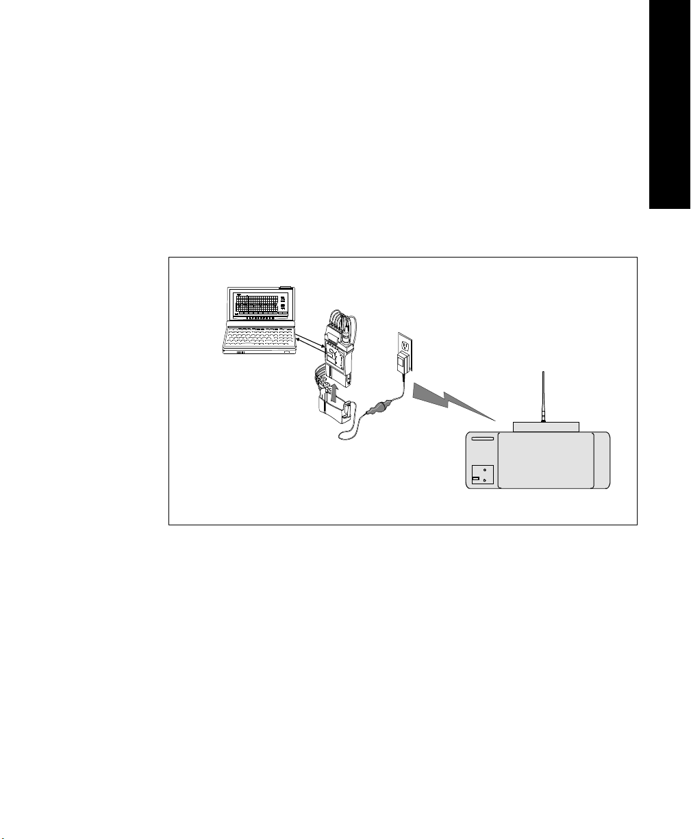
The transmitter can also be connected via an infrared link to the Wave Viewer or
TeleMon to provide display of patient measurements and waveforms at the
patient’s side.
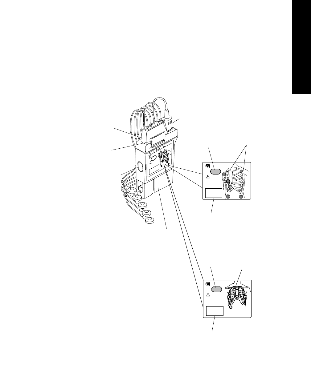
SpO
2
Transducer
Connection
ECG Lead
Set
Connection
Combiner
Clip
Infrared Link to
Wave Viewer and
TeleMon
Transmitter
Button
4
Transmitter
Label
Battery
Compartment
Chest Diagram
with
LEADS
OFF Lights
For Standard
ECG
Transmitter
(label is dark
green)
EASI Chest
EASI
1
2
3
4
5
Diagram with
LEADS OFF
Lights
For
EASI
Transmitter
(label is
purple)
Transmitter
Button
4
Transmitter
Label
Introduction to the Philips Telemetry System
1-7
Page 24

Transmitters
ECG Connection: The Philips Transmitter supports a 3- or 5-wire ECG cable
compatible with Philips CMS/24 ECG trunk cables. The Philips EASI
Transmitter supports 5-wire ECG cables only (use of a 3-wire cable set
generates an INOP condition). CMS trunk cables must include telemetry
combiners. In addition to keeping dirt out of the connectors, the combiner has a
locking mechanism to keep the lead set attached securely to the transmitter. For
safety, every lead should be secured to an electrode on the patient.
Warning
Conductive parts of electrodes should not contact earth or other conductive
parts.
Disconnection of Leadset: When you’re ready to disconnect the leadset, lift
the clip of the combiner to release the lock. Then, holding the combiner firmly,
rock the leadset free. Do not pull on the lead wires or push on the combiner clip.
SpO
Connection: In addition, both the standard ECG and EASI transmitter
2
support a SpO
transducer (sensor) connection. SpO2 can be measured
2
continuously, intermittently at 1 or 5 minute intervals, or manually. Reusable
sensors in adult finger, small adult/pediatric finger, and ear clip models can be
used, as well as Oxisensor II™ disposable sensors. See Appendix B,
“Accessories and Ordering Information” for a list of sensors.
Chest Diagram & LEADS OFF Lights: The diagram on the front of the
standard ECG transmitter shows lead placement for a 5-wire lead set. The white,
black and red electrode positions represent standard AAMI 3-lead placement;
the red, yellow and green electrode positions represent standard IEC 3-lead
placement. Non-standard 3-wire lead placement diagrams are available at the
Wave Viewer.
The diagram on the front of the EASI transmitter shows EASI lead placement
for a 5-wire lead set. The AAMI colors that are used for EASI are brown (E),
red (A), black (S), white (I), and green (reference). The IEC equivalents for
EASI are white (E), green (A), yellow (S), red (I), and black (reference).
On both transmitters, each electrode position has a light that illuminates if the
corresponding electrode becomes detached. In a LEADS OFF situation, this
indicator will help you identify quickly which leads are off and re-attach them.
If the reference lead is off, after you correct the situation you may find other
lights illuminated as well.
1-8 Introduction to the Philips Telemetry System
Page 25
Transmitters
A second function of the Leads Off lights is to indicate successful power-up of
the transmitter. When you insert a battery into the transmitter, all five lights
should flash once. This indicates that the battery has adequate power for
monitoring and that there is no transmitter malfunction. See “Inserting Batteries”
on page 1-18 for details.
1 System Introduction
Philips Telemet ry Battery Extender
The electrode lights are also used as an indicator that a manual SpO
measurement has been initiated at the transmitter.
The Philips Telemetry Battery Extender (M2611A) enables operation of the
transmitter with an external power source when a patient is not ambulating. The
battery extender can be used with Release B and C Philips transmitters, and
earlier transmitters that have been upgraded.
The battery extender consists of a cradle, which is fitted over the battery
compartment of the transmitter, and a cable connecting to a wall-mounted DC
power module. When the battery extender is in use, no battery power is used
(battery save mode).
Note—The purpose of the battery extender is to conserve battery life; the
extender does not recharge the battery.
Power
Module
2
Alignment
Groove
Cradle
Connector
Cradle Wire
Philips Telemetry Battery Extender
Introduction to the Philips Telemetry System
Power Cable
1-9
Page 26
Transmitters
Connecting to the Battery Extender
To use a transmitter in battery-save mode, connect the transmitter to the battery
extender in the following steps:
Step Action
1 Align the grooves on the transmitter battery door and battery
extender cradle. Slip the cradle onto the base of the transmitter, and
press until you hear a click.
Note—For accurate functioning, the battery cover must remain
closed when the extender is in use. In addition, Philips Medical
Systems recommends that the battery remain in the transmitter while
the extender is in use.
2 Connect the aqua connector between the cradle wire and the power
cable. Be sure the connection is secure; the yellow band of the
connector should be completely covered.
3 Insert the power module into a wall power source.
1-10 Introduction to the Philips Telemetry System
Page 27

Transmitters
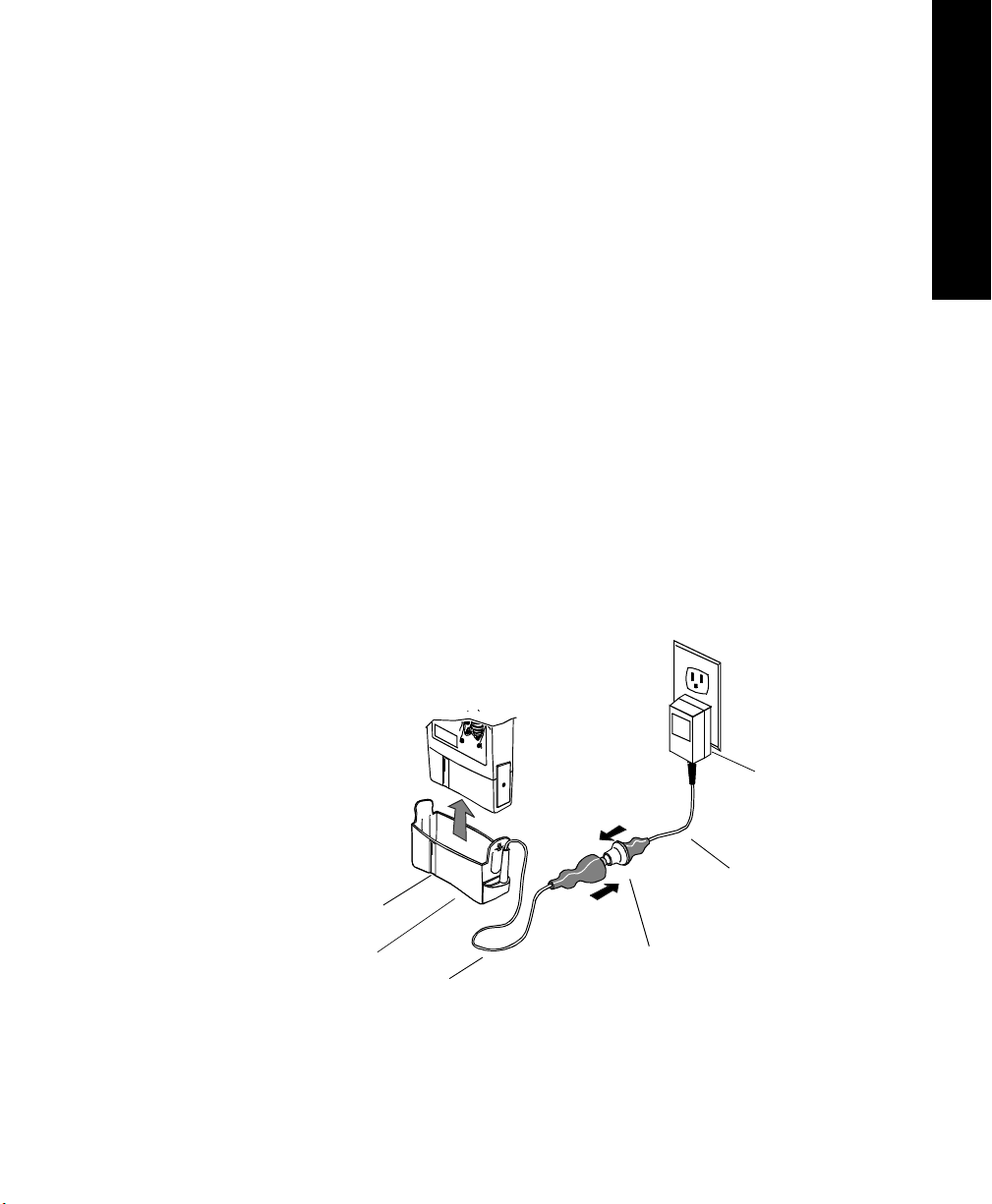
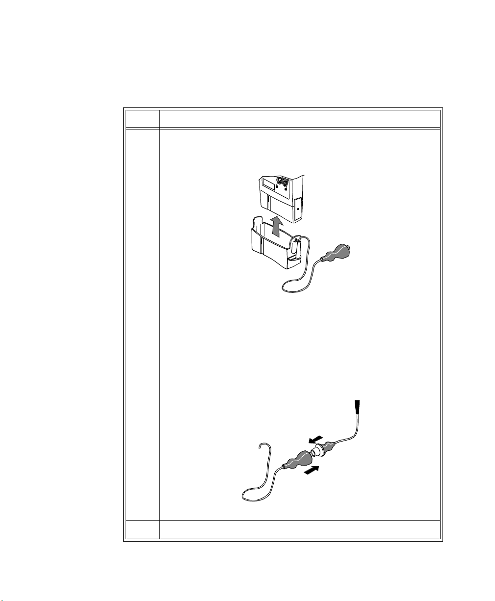
Disconnecting from the Battery Extender
To disconnect the transmitter from the battery extender for ambulatory
monitoring, perform the following steps:
Step Action
1 Disconnect the aqua connector between the cradle wire and the
power cable.
Note—The connector is designed to come apart on its own if the
patient gets up without disconnecting the connector.
2 Tuck the loose end of the cradle wire into the pouch.
Warning
DO NOT UNPLUG THE POWER MODULE BEFORE REMOVING THE
CRADLE OR DISCONNECTING THE AQUA CONNECTOR.
If you unplug the power module before you disconnect the aqua connector
(or remove the cradle):
1 System Introduction
- The transmitter may reset automatically before switching to battery
power, making data unavailable at the Philips Information Center for a
brief interval.
- Or, the transmitter may stop sending signals, and a NO SIGNAL INOP
will be displayed at the Philips Information Center. In this case, restart
monitoring manually by removing and reinserting the transmitter
battery.
Introduction to the Philips Telemetry System
1-11
Page 28

Transmitters
Transmitter Features
Transmitter
Button
Water
Resistance
The transmitter has a transmitter button (see page 1-7). Depending on how it is
configured, pressing this button produces:
• A “Nurse Call” message and tone
• A “Nurse Call” message and tone, plus a delayed recording
• A delayed recording
• No response at the Philips Information Center.
Note—Delayed recordings generated by the transmitter button are stored in
Alarm Review.
If desired, you can turn the transmitter button off for individual patients at the
Philips Information Center by using the Telemetry Setup Window. See “Turning
the Transmitter Button On/Off” on page 2-8 for additional information.
The transmitter button can also be used to initiate an SpO
“Making SpO
Measurements” on page 4-6 for more information.
2
measurement. See
2
The transmitters and the battery extender (except the power module) can
withstand submersion in water for 5 minutes and exposure in a shower for 10
minutes. If the battery compartment gets wet, remove the battery and wipe the
compartment dry before monitoring. See “Chapter 5. Telemetry System
Cleaning” for details.
Caution
Disconnect the battery extender cradle from the power module prior to a
patient’s showering.
Earlier Philips transmitters are also resistant to water. If either transmitter is
exposed to liquids, remove the battery and dry the battery compartment
thoroughly before monitoring.
If the transmitter or battery extender needs cleaning, follow the instructions in
“Cleaning the Transmitter & Battery Extender” on page 5-4.
1-12 Introduction to the Philips Telemetry System
Page 29

Transmitters
Pouch Use During normal use, the transmitter should be worn over clothing, in a pocket, or
preferably in a pouch.
Warning
Place the transmitter in a pouch or over clothing, or both, during patient
use. The transmitter should not touch the patient’s skin during normal use.
1 System Introduction
Automatic
Shutoff
Battery Information
A service feature of the transmitter is RF Automatic Shutoff, which causes the
transmitter to stop broadcasting a radio signal if there is no ECG signal for 10
minutes. This prevents interference with other transmitters in use. The INOP
message at central is TRANSMITTER OFF. To restart monitoring, attach leads
to the patient. Automatic Shutoff can be configured off. When configured off,
batteries must be removed and the battery extender should be disconnected when
the transmitters are not in use to prevent RF interference and unnecessary
battery drain.
The Philips Transmitter battery compartment is capable of accommodating any
type of standard 9 volt battery. An 8.4 volt Zinc-Air battery can be used with the
both the EASI ECG and standard ECG-only version of the transmitter. The
transmitter was not designed for use with rechargable batteries.
The battery compartment is located at the bottom of the transmitter. The length
of time the battery lasts depends on:
• The type of transmitter.
• The battery.
• The parameters being monitored - ECG only, ECG and continuous SpO
or ECG and intermittent SpO
When battery power is running low, the INOP message BATTERY WEAK
appears in the patient sector to indicate there is at least 15 minutes of battery life
remaining.
.
2
2
,
When there is no battery life remaining, the INOP message REPLACE
BATTERY is displayed.
Introduction to the Philips Telemetry System
1-13
Page 30

Transmitters
Note—If the BATTERY WEAK message appears when you are making a STAT
SpO
measurement, or changing the SpO2 sample rate out of Manual, it may be
2
necessary to replace the battery immediately in order to continue monitoring.
Be careful not to short circuit the battery. Short circuiting is caused when a piece
of metal touches both buttons (positive and negative terminals) at the top of the
battery simultaneously (for example, carrying batteries in a pocket with loose
change). More than a momentary short circuit will generally reduce the battery
life.
Warning
Certain failure conditions, such as extended short circuiting, can cause a
battery to overheat during normal use. High temperatures can cause burns
to the patient and/or user, or cause the battery to flame. If the transmitter
becomes hot to the touch, place it aside until it cools. Then remove the
battery and discard it. It’s a good idea to place a piece of tape across the
contacts of the battery to prevent inadvertent shorting. Have transmitter
operation checked by service to identify the cause of overheating.
The battery should be removed when the transmitter is stored.
Warning
Batteries should be removed from the transmitter at the end of the
battery’s useful life to prevent leakage.
Warning
If battery leakage should occur, use caution in removing the battery. Avoid
contact with skin. Clean the battery compartment according to instructions
in “Chapter 5. Telemetry System Cleaning”.
1-14 Introduction to the Philips Telemetry System
Page 31

Transmitters
1 System Introduction
Use of Zinc-Air
Batteries
Maximizing
Battery Life
Zinc-Air batteries can be used with ECG-only models of the transmitter,
revision A.01.02 and later. A Zinc-Air battery cannot be used with an ECG/
SpO
transmitter.
2
For maximum performance, observe the following guidelines:
• Use Zinc-Air batteries within 1 year of manufacture.
• Use Zinc-Air batteries within three months of opening the sealed package.
• Store and use Zinc-Air batteries at near room temperature. They can lose
50% of their capacity at low temperatures (0
o
C /32oF and below).
• Do not put Zinc-Air batteries in an environment with restricted air flow
(e.g., a plastic bag). Restriction of air flow can affect battery capacity.
During normal use, the battery compartment provides adequate air flow.
• Zinc-Air batteries may take up to 1 minute to get to working voltage after
removal from the airtight wrapper. Shaking the battery can speed this.
By observing the following guidelines, you can optimize battery life in the
Philips transmitter:
• REMOVE THE BATTERY (or turn it over/up-end it) when the
transmitter is not in use.
Note—Automatic Shutoff does not save battery life. In order to allow an
automatic turn-on, the transmitter ECG and SpO
functions are not
2
completely disabled in this mode.
•For SpO
the SpO
transmitters, when the SpO2 function is not in use, make sure
2
sample rate is set to Manual. See “Changing the SpO2 Sample
2
Rate” on page E-10 for directions.
• If using Wave Viewer, be sure to press End STAT at the end of every
STAT SpO
measurement that is initiated at the Wave Viewer and wait
2
for the red sensor light to go out before removing the transducer.
• If using TeleMon, see the TeleMon Instructions for Use page 3-7.
Disposal of
Batteries
Philips Medical Systems recommends that you remove the battery when the
transmitter is not in use.
Caution
The battery must be removed if a transmitter will be stored for an extended
period of time.
Important—When disposing of batteries, follow local laws for proper disposal.
Dispose of batteries in approved containers. If local regulations require you to
recycle batteries, recycle batteries in accordance with regulations.
Introduction to the Philips Telemetry System
1-15
Page 32

Transmitters
Nominal Battery Life Expectancy
Recommended
Battery Types
Lithium
1
(supplied)
Alkaline
Zinc-Air
2
1 day, 18 hours 8 hours 1 min. intervals:
3
Battery life is determined by the transmitter’s serial number prefix date code,
which is located inside the transmitter’s battery compartment.
Following are tables for Transmitters with:
Prefix Date Codes 3836A through 4014A - (Transmitter Serial Number
Prefix Date Code greater than or equal to 3836A but less than 4015A.)
Nominal Life
Expectancy ECG Only
3 days, 20 hours 14 hours 1 min. intervals:
Nominal Life
Expectancy ECG &
Continuous
4
SpO
2
Nominal Life
Expectancy ECG &
Intermittent
SpO
2
Nominal Life
Expectancy ECG with SpO
Transducer
Detached
2 days, 12 hours
1 day, 19 hours
5 min. intervals:
2 days, 22 hours
1 day, 4 hours
20 hours
5 min. intervals:
1 day, 10 hours
4 days, 18 hours Not Applicable Not Applicable Not Applicable
2
1
Tested with ULTRALIFE U9VL batteries.
2
Tested with DURACELL MN1604 batteries.
3
Tested with DURACELL DA146 batteries.
4
Life expectancy is based on transmitter current draw of 52.4 mA.
1-16 Introduction to the Philips Telemetry System
Page 33

Transmitters
Prefix Date Codes 3751A through 3835A - (Transmitter Serial Number
Prefix Date Code greater than or equal to 3751A but less than 3836A.)
1 System Introduction
Recommended
Battery Types
Lithium
Nominal Life
Expectancy ECG Only
3 days 16 hours 1.5 - 2.5 days
Nominal Life
Expectancy ECG &
Continuous
4
SpO
2
Nominal Life
Expectancy ECG &
Intermittent
SpO
2
(supplied)
*
Alkaline
Zinc-Air
*
Tested with DURACELL battery.
1 day, 8 hours 8 hours 1 day
*
3 days, 18 hours Not Applicable Not Applicable
Prefix Date Codes 3732A through 3750A - (Transmitter Serial Number
Prefix Date Code greater than or equal to 3732A but less than 3751A.)
Nominal Life
Expectancy ECG &
Intermittent
SpO
2
Recommended
Battery Types
Nominal Life
Expectancy ECG Only
Nominal Life
Expectancy ECG &
Continuous
4
SpO
2
Lithium
3 days, 6 hours 16 hours 1.5 - 2.5 days
(supplied)
Alkaline
*
Tested with DURACELL battery.
*
1 day, 8 hours 8 hours 1 day
Introduction to the Philips Telemetry System
1-17
Page 34
Transmitters
Inserting Batteries
Task Summary
Insert a battery into a transmitter by performing the following steps:
Step Action
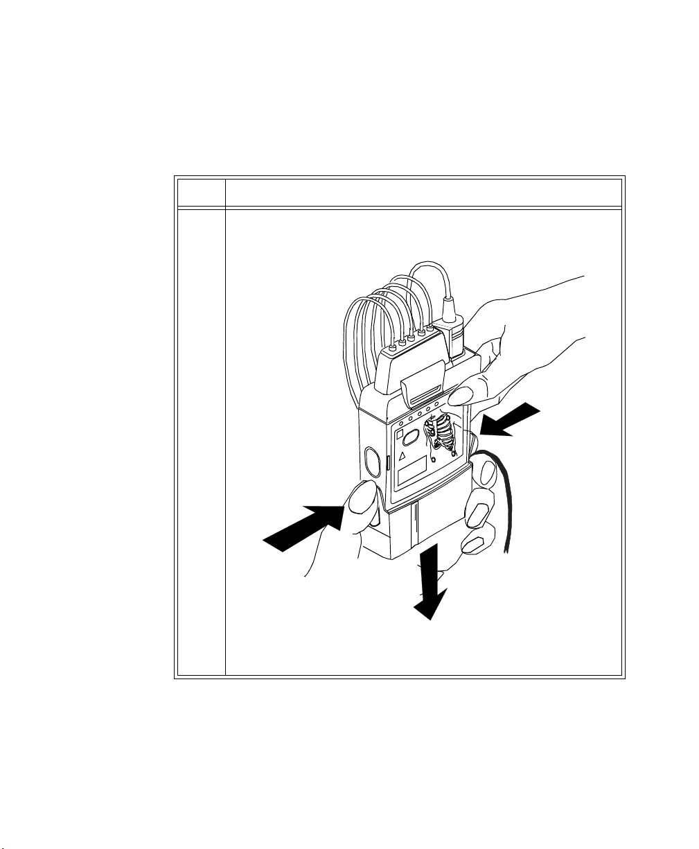
1 Remove the battery extender, if present, by squeezing the tops of the
tabs (1) and sliding the cradle away from the transmitter (2).
1
1
1-18 Introduction to the Philips Telemetry System
2
2
Page 35

Step Action
2 Open the battery compartment by pressing down on the
compartment door and swinging it 45° into an open hinged position.
Caution
Forcefully opening the compartment door to a full 90° will break the
hinges.
3 Insert the battery, matching the battery polarity with the +/-
indication inside the compartment.
1 System Introduction
Transmitters
Introduction to the Philips Telemetry System
1-19
Page 36

Transmitters
Step Action
4 When the battery is active after a few seconds, all five of the lights
on the chest diagram flash once, then each light flashes individually.
Next, if no leadset is attached, one light remains on, or if the
transmitter is connected to a patient, no lights remain on.
• If no lights flash, use a second new battery. If there are still no
lights, the transmitter memory may be corrupt. Contact
Service.
• If the lights come on but do not behave as described above,
the transmitter has malfunctioned. Contact Service.
IMPORTANT: When you replace the battery in a transmitter
connected to a patient, if either abnormal condition is in effect, no
monitoring will be occurring for the patient until either a new
battery or a replacement transmitter is used.
1-20 Introduction to the Philips Telemetry System
Page 37

Receiver Module
The Philips receiver modules are housed in the receiver mainframe. Each
receiver module is dedicated to a specific transmitter by an internal identity
code. This prevents another patient's waveform from being erroneously
transmitted and displayed. The receiver acquires the ECG and SpO
from the transmitter and sends them to the receiver mainframe.
Receiver Mainframe
Receiver Module
signals
2
1 System Introduction
Receiver Module
Front Cover
Introduction to the Philips Telemetry System
1-21
Page 38

Receiver Mainframe
Receiver Mainframe
The Philips receiver mainframe houses up to eight receiver modules. For each
receiver, the receiver mainframe calculates the heart rate, and sends the
waveform, alarms, inoperative messages (INOPs), and status messages over the
Philips patient care system to the Philips Information Center for display and
recording. If SpO
the Philips Information Center via the network as well.
is available, the transmitter processes the data and sends it to
2
Turning the
Receiver
Mainframe On
or Off
Receiver
Mainframe
Malfunction
Light
Channel
Frequencies
Retaining
Telem e t ry
Settings
The receiver mainframe must be turned on for individual transmitters and
receivers to work. To turn the receiver mainframe on, the power cord must be
attached and connected to an ac outlet. A green LED on the rear of the
Mainframe will light then.
If the receiver mainframe is turned off, the light and all receiver modules are off.
A red light on the front panel of the mainframe illuminates when either the
mainframe or one of the receivers has malfunctioned. Depending on the
problem, you may see the message, NO DATA FROM BED, in single or
multiple patient sectors. Contact your Philips Medical Systems Service
Representative.
When the mainframe is first turned on, the red light flashes. If no problems are
detected, the flashing stops and the light turns off.
The frequency of Philips transmitters and receivers are programmable, thus
enabling changes in frequency if interference is detected. In case of interference,
contact service.
If power to the receiver mainframe is interrupted or turned off, settings
controlled by the mainframe such as leads may be affected.
• If the receiver mainframe is turned off for less than three hours, your
settings should still be in effect.
• If the mainframe is turned off for more than three hours, your settings
revert to default, that is, to the configured settings at installation.
1-22 Introduction to the Philips Telemetry System
Page 39

Antenna System
The telemetry antenna system is custom-designed for your unit to ensure
adequate coverage, therefore the telemetry signal can only be received where
there are receiving antennas. After it is received by the antenna system, it is sent
to the receiver which recovers the patient's ECG and optional SpO
information is then sent to a monitoring display.
Antenna System
. This
2
1 System Introduction
Introduction to the Philips Telemetry System
1-23
Page 40

Turning Telemetry On/Off
Turning Telem et ry On /Off
Telemetry monitoring can be turned on or off in one of several ways:
• Manually, by activating Monitoring Standby at the Philips Information
Center (click on Patient Window, then Standby). This action creates a
TELEMETRY STANDBY message on the display. To restart monitoring,
click on
• Automatically, if Auto Shutoff is enabled at the transmitter and if there is
no ECG signal for 10 minutes. This situation creates a TRANSMITTER
OFF inop at central. To restart monitoring, re-attach the lead wires.
• Manually, by removing the transmitter battery. This action creates a NO
SIGNAL inop at central. To restart, insert the battery.
Resume Monitoring in the Patient Sector.
1-24 Introduction to the Philips Telemetry System
Page 41

2
ECG Monitoring
This chapter provides information on setting up and managing ECG monitoring.
It includes the following sections:
• Lead Sets & Capabilities . . . . . . . . . . . . . . . . . . . . . . . . . . . . . .2-2
• Preparing for ECG Telemetry Monitoring . . . . . . . . . . . . . . . . . .2-5
• Making ECG Adjustments . . . . . . . . . . . . . . . . . . . . . . . . . . . . .2-7
• Making Other Monitoring Adjustments . . . . . . . . . . . . . . . . . . . .2-8
• Monitoring During Leads Off. . . . . . . . . . . . . . . . . . . . . . . . . . .2-10
• Optimizing System Performance . . . . . . . . . . . . . . . . . . . . . . .2-12
• ECG Alarm Summary . . . . . . . . . . . . . . . . . . . . . . . . . . . . . . . .2-16
• Telemetry Alarm & INOP Summary . . . . . . . . . . . . . . . . . . . . .2-17
2 ECG Monitoring
ECG Monitoring 2-1
Page 42

Lead Sets & Capabilities
Lead Sets & Capabilities
Standard ECG Transmitter
The standard ECG Transmitter supports 3- and 5-wire cables. The table below
provides a summary of the capabilities of each cable.
Note—For details of electrode placement, see the Philips Information Center or
TeleMon online Help. For 3-wire electrode placement with Lead Select turned
off, see also the Wave Viewer Help.
Lead
Set
3-wire
-Lead
Select
Off
Number
of Leads
1 • Position electrodes for desired
Lead/Label Choices
lead. Standard placement gives
Lead II.
See the on-line help in the
Wave Viewer for information
on electrode placement.
• Select
Warning
Philips Medical Systems
recommends you change the lead
label only to reflect the physical
placement of the electrodes. This
ensures that the monitored lead
and the label match, and
prevents any possible confusion.
Label to match
electrode placement.
Primary
I, II, III, MCL
Secondary
Not available
2-2 ECG Monitoring
Page 43

Lead Sets & Capabilities
Lead
Set
3-wire
Lead
Select
On
5-wire 2 • Position electrodes in standard
Number
of Leads
1 • Position electrodes in standard
Lead/Label Choices
placement.
• Use the Wave Viewer to
change the lead that is
transmitted to the Philips
Information Center (see
“Changing the Lead (Standard
ECG only)” on page 6-7).
Lead selection at the Philips
Information Center is disabled.
placement.
Standard placement provides
V1 or MCL1. To monitor a
different chest lead, for
example, V6 or MCL6,
position chest electrode
appropriately.
• Select
Lead.
Primary
I, II, III
Secondary
Not available
2 ECG Monitoring
Primary
I, II, III, aVL,
aVR, aVF, V,
MCL
Secondary
I, II, III, aVL,
aVR, aVF, V,
MCL
ECG Monitoring
2-3
Page 44

Lead Sets & Capabilities
Philips EASI Transmitter
1
2
3
4
5
EASI
The Philips EASI Transmitter supports 5-wire cables. The table below provides
a summary of this cable’s capabilities.
Note—For details of EASI electrode placement, see the Philips Information
Center Online Help.
Lead
Set
5-wire 2 • Position electrodes in EASI
Number
of Leads
Lead/Label Choices
.
Primary
placement.
EASI placement provides a
derived Lead II for overview.
•Click 12-Lead ECG to display
a 2.5 second ECG wave of
each of the 12 derived leads.
If there is an INOP condition
in any lead, it is not possible to
display the 12-lead waves.
Note—With EASI, although you
I, II, III, aVL,
aVR, aVF, V1,
V2, V3, V4,
V5, V6
Secondary
I, II, III, aVL,
aVR, aVF, V1,
V2, V3, V4,
V5, V6
can view and do ST
analysis on all 12 derived
leads, arrhythmia
monitoring can only be
done on 2 leads.
2-4 ECG Monitoring
•Click 3 EASI Leads to view
the AI, AS, and ES leads and
troubleshoot ECG waveform
quality problems.
Page 45

Preparing for ECG Telemetry Monitoring
Preparing for ECG Telemetry Monitoring
Overview The Philips Telemetry System provides remote monitoring of the patient’s ECG
for adult and pediatric patients.
Task Summary
Note—For SpO
Perform the following steps to set up for telemetry ECG monitoring:
Step
1 Insert a battery into the transmitter, following the +/- diagram on the
2 Connect the lead set to the transmitter by pushing it down firmly
3 Prepare the skin by:
4 Attach the electrodes to the lead wires.
5 Remove electrode backing and check for moist gel.
setup, see Chapter 4, “SpO2 Monitoring”
2
Action
inside of the compartment. See “Inserting Batteries” on page 2-18.
until it “locks.” You should hear a click.
1. Shaving the hair from electrode sites if necessary.
2. Washing the sites (preferably with soap and water), and rinsing
well.
3. Drying briskly to remove skin cells and oils.
Note—Use electrodes that are all the same brand and change all the
electrodes every 24 hours.
2 ECG Monitoring
6 Apply electrodes to the skin by placing the edge down, then “rolling
down” the rest of the pad. Press firmly around the adhesive edge
toward the center. See the on-line help for information on electrode
placement. Or, for 3-wire cables only with Lead Select off, see the
Wave Viewer ECG screen or TeleMon on-line Help for lead
placement information.
7 If available, verify lead placement using the TeleMon.
ECG Monitoring
2-5
Page 46

Preparing for ECG Telemetry Monitoring
EASI 12-lead Monitoring
1
2
3
4
5
Step
Action
8 Verify the lead placement using the Wave Viewer. See “Checking
ECG Signal Quality” on page 2-4.
9 Support the transmitter by using a pouch, and if necessary, tape the
lead wires to the chest.
10 Teach the patient how and when to press the transmitter button.
11 Make adjustments to ECG wave(s) and alarm limits in the Patient
Window. See “Making ECG Adjustments” on page 2-7.
12 If using EASI, turn arrhythmia monitoring on for this patient. See
the Philips Information Center User Guide for instructions. Refer to
the next section for additional information on EASI monitoring.
During monitoring, respond promptly to INOP conditions to prevent loss of
monitoring.
EASI 12-lead ECG monitoring (for use only on adult and pediatric patients)
allows you to derive all 12 standard ECG leads, using a 5-wire electrode cable
and special electrode placement (see the online Help on the Philips Information
Center for lead placement information or refer to the diagram in Appendix C).
EASI monitoring also enables the monitoring of ST changes with a full 12-lead
ECG.
EASI
2-6 ECG Monitoring
When using EASI monitoring,
• Any telemetry EASI bed must be arrhythmia-monitored. If arrhythmia is
not on, the INOP “ARRHY REQUIRED” is shown and no waves or
parameters are displayed.
• When placing electrodes, be careful to place the electrodes as accurately
as possible or the derived leads may be incorrect.
Page 47

Making ECG Adjustments
Making ECG Adjustments
Overview You can make the following adjustments from the Philips Information Center:
• Change the lead or the lead label.
• Change the wave size.
With 5-wire lead sets, you can monitor two leads. With a 3-wire lead set you can
monitor one lead. When monitoring two leads, the first lead is the primary lead.
Single lead arrhythmia analysis uses this lead. It is also the lead used for alarm
and delayed recordings. Multilead analysis uses both leads.
If you are not receiving a good ECG wave and the electrodes are securely
attached, you should try changing the lead in which you are monitoring.
Bandwidth Bandwidth is not user adjustable, but is assigned automatically by the
information center. The settings are:
Setting Bandwidth
ST off Monitor (0.5-40 Hz)
ST on ST (0.05 to 40 Hz)
2 ECG Monitoring
Changing Lead/Label
Adjusting Wave Size
To change the lead/label place your cursor over the wave in the Patient Window
and select the lead or label from the pop-up box to match the placement.
To change the amplitude of the ECG wave on the display or for recordings,
place your cursor over the wave in the Patient Window and select the size you
want from the pop-up box. There are five sizes available: 1/4 (smallest), 1/2, 1,
2, and 4 (largest).
You can use the 1 mV cal bar on the Patient Window to check the height of the
R-wave. If the wave is not at least 0.5 mV high (one-half the size of the cal bar),
change the lead.
0.5 mV
1 mV
ECG Monitoring
2-7
Page 48

Making Other Monitoring Adjustments
Making Other Monitoring Adjustments
Turning the Transmitter Button On/Off
Overview You can turn the Transmitter Button on the transmitter on or off by using the
Telemetry Setup Window. Turning the Transmitter Button off inhibits Nurse
Call alarms and/or recordings depending on how your system is set up.
Task Summary Turn the
following steps:
Step Action
1 On the Patient Window click the
2 On the All Controls Window click the
3 On the Telemetry Setup Window turn the
Note—Manual SpO
button even when the button is turned off at the central. See “Making SpO
Measurements” on page 4-6.
Transmitter Button on the transmitter on or off by performing the
All Controls button.
Telemetry Setup button.
Transmitter Button on or
off by clicking in the
Transmitter Button Allow Calls checkbox. A
check mark in the checkbox indicates that the transmitter button is
on.
measurements can still be made using the transmitter
2
2
2-8 ECG Monitoring
Page 49

Making Other Monitoring Adjustments
Standby Mode
Task Summary Place a patient in Standby by performing the following steps:
When a patient is temporarily off the unit or out of antenna range you can
suspend monitoring by placing telemetry in Standby Mode. Standby suspends
monitoring, and you won’t get any waveforms or alarms.
If a patient leaves the unit without a transmitter, place telemetry in Standby.
Note—If you remove the leads before putting a patient into Standby, you’ll get a
LEADS OFF INOP, and reminders if configured.
Warning
If you put telemetry in Standby Mode, you must remember to turn
monitoring back on when the patient returns to the unit.
Note—When you take an EASI transmitter out of Standby, the lead settings
revert back to the central’s default lead settings (i.e., II and V2).
Step Action
1 On the Patient Window click the Standby button.
2 Select the patient’s location from the pre-defined list.
2 ECG Monitoring
3 Click the Suspend Monitoring button. This indefinitely suspends
all monitoring and displays the following messages in the Patient
Sector NO DATA FROM BED and TELEMETRY STANDBY and
the location (for example, X-Ray).
Note—Be sure to take the bed out of Standby before discharging.
Since Standby is associated with the equipment assigned to a bed, if
a patient is discharged and the bed is in Standby Mode, that
equipment will be in Standby for the next patient, and monitoring
will continue to be interrupted.
4 When the patient comes back, restart monitoring by clicking on
Resume Monitoring in the Patient Sector.
ECG Monitoring
2-9
Page 50

Monitoring During Leads Off
1
2
3
4
5
EASI
Monitoring During Leads Off
Fallback
Multilead
Analysis
Singlelead
Analysis
Fallback for
EASI
If there is a Leads Off INOP in the primary lead for >10 seconds, the active
secondary lead becomes the primary lead. This is known as lead fallback. In lead
fallback, the arrhythmia system switches the leads on the display. When the
Leads Off condition is corrected, the leads are switched back.
For single lead analysis, if there are two leads available, the other lead is made
the primary lead (until the Leads Off condition is corrected).
If one of the derived EASI leads has an INOP condition (for example, LEADS
OFF), a flat line is displayed. After ten seconds, the directly acquired EASI AI,
AS, or ES lead (depending on which is available) is displayed with the label
“ECG” and is analyzed by the arrhythmia system.
• Whenever there is an INOP condition (i.e., LEADS OFF), the arrhythmia
algorithm performs a Relearn, using the available leads.
Warning
Since Relearn happens automatically, if learning takes place during
ventricular rhythm, the ectopics may be incorrectly learned as the normal
QRS complex. This may result in missed detection of subsequent events of
V-Tach and V-Fib. For this reason, you should:
1. Respond promptly to the INOP message (for example, re-connect
the electrodes.
2-10 ECG Monitoring
2. Ensure that the arrhythmia algorithm is labeling beats correctly.
Note—If there is artifact in the ECG waves or a CANNOT ANALYZE ECG
INOP condition, you can use the three EASI leads to troubleshoot.
Click 12-Lead ECG on the Patient Window, then on 3 EASI Leads.
2. The three directly acquired EASI leads will be displayed so that you can
determine which electrodes are causing the problem and need to be
replaced.
Page 51

Monitoring During Leads Off
Extended Monitoring
When both the primary and secondary leads have a Leads Off condition, if
another lead is available it becomes the primary lead and the system does a
relearn. This is called extended monitoring.
Extended monitoring applies if:
• Telemetry is configured for extended monitoring ON.
• The leadset provides more than two leads (i.e., when using a 5-wire
leadset).
2 ECG Monitoring
ECG Monitoring
2-11
Page 52

Optimizing System Performance
Optimizing System Performance
While telemetry monitoring offers many advantages, it can be a challenge. The
reliability and quality of the signal transmission through the air and hospital
walls is governed by a number of variables which can be difficult to control. A
telemetry system cannot be as dependable as a hardwired bedside monitor that
transmits its signal through a wire.
The effect of interference on the telemetry system ranges from a momentary loss
of ECG to complete inoperability, depending on the situation. The strength,
frequency, and proximity of the source of interference to transmitters or the
antenna system are factors that determine the degree of severity. In cases where
the source of interference is known - for example, cellular phones, magnetic
equipment such as MRI, other radio or motorized equipment - removing or
moving away from the source of interference will increase the system's
dependability.
Warning
Telemetry should not be used for primary monitoring in applications where
the momentary loss of the ECG is unacceptable.
The Telemetry Signal
2-12 ECG Monitoring
In this section, we'll investigate some of the problems affecting ECG signal
clarity and when possible, show you how you can greatly enhance performance.
Note—The telemetry system also emits radio frequencies (defined in “System
Specifications” on page 7-19) that may affect the operation of other devices.
Contact the manufacturer of other equipment for possible susceptibility to these
frequencies.
The transmitter worn by the patient acquires the patient's physiological data,
amplifies and digitizes it, detects pace pulses and broadcasts this information via
radio waves to the antenna system. Since the signal passes through the air, it is
susceptible to interference from many sources.
Page 53

Optimizing System Performance
Frequent Signal Strength and RF INOPs
Signal
Strength
Because the telemetry system is a wireless system, under certain conditions RF
“dropouts” can occur. Dropouts result from a weak signal or RF interference.
There will be signal drops to the bottom of channel for a minimum of 200 ms to
indicate to the clinical user that it is a non-physiological event. If dropouts are
frequent enough to affect the heart rate count, the TEL CANNOT ANALYZE
INOP occurs. The following recording strip is an example of dropouts.
2 ECG Monitoring
If frequent dropouts are occurring, the following section describes some steps
you can take to improve performance.
The antenna system is custom designed for your unit, so reliable signal reception
is only possible where there are receiving antennas. When the signal is too low,
the following INOPS occur:
• TEL CANNOT ANALYZE
• WEAK SIGNAL
• NO SIGNAL
To correct, first check the location of the patient. If not in the coverage area, do
one of the following.
• Return the patient to the specified antenna coverage area.
• Put telemetry in Standby Mode. See “Standby Mode” on page 2-9.
Warning
If you put telemetry in Standby Mode, you must remember to turn
monitoring back on when the patient returns to the unit. See “Standby
Mode” on page 2-9.
• If the patient is in the coverage area and is stationary, try moving the
location of the transmitter or patient about six inches.
ECG Monitoring
2-13
Page 54

Optimizing System Performance
Radio
Frequency
Interference
Radio frequency (RF) interference is caused by anything that intrudes into the
transmitted electrical signal, such as paging transmitters and walkie-talkies. We
are all familiar with electrical interference in our homes and cars when it causes
“snow” on the television and static on the radio station. These same types of
interference can occur with the transmitted telemetry signal. Even though the
Philips Telemetry System is designed to resist these effects, interference can
occasionally be seen in the form of “dropouts”. To improve performance, the
source of the interference must be identified and eliminated.
Muscle and
Movement
Artifact
Muscle and movement artifact differ from radio frequency interference since
you can prevent much of the occurrence. Noise on the ECG signal can be caused
by many sources, such as interference from other electrical equipment, muscle
artifact and respiration variation. It is up to the clinician to use certain
techniques to minimize these types of noise. Use the following table to help you
troubleshoot the most common sources of ECG noise.
Problem Cause Remedy
60-Cycle (AC)
Interference
Poor electrode
placement.
Re-apply electrodes
Disconnect electrical appliances near
Possible non-grounded
instrument near patient
patient (one at a time) by pulling wall
plugs, to determine faulty grounding.
Have engineering check grounding.
Muscle Artifact Tense, uncomfortable
patient.
Poor electrode
placement.
Tremors.
Diaphoresis
Irregular Baseline Poor electrical contact.
Respiratory interference.
Faulty electrodes.
Dry electrodes.
2-14 ECG Monitoring
Make sure patient is comfortable.
Check that electrodes are applied on flat
non-muscular areas of the torso; dry the
skin and re-apply the electrodes if
necessary.
Re-apply electrodes, using proper
technique.
Move electrodes away from areas with
greatest movement during respiration.
Page 55

Problem Cause Remedy
Optimizing System Performance
Baseline Wander Movement of patient.
Improperly applied
electrodes.
Respiratory interference.
Poor Electrode Contact Loose electrodes.
Defective cables.
Lead set not firmly
connected.
Make sure patient is comfortable.
Re-apply electrodes. Check that patient
cable is not pulling electrodes.
Move electrodes away from areas with
greatest movement during respiration.
Change electrodes, using good skin prep.
Replace cables.
2 ECG Monitoring
ECG Monitoring
2-15
Page 56

ECG Alarm Summary
ECG Alarm Summary
The following table lists the ECG alarms that can be generated by the Telemetry
System when using the standard ECG transmitter. These are announced at the
Philips Information Center when arrhythmia monitoring is turned off at central.
Note—When arrhythmia monitoring is turned on at central, ECG alarms are
generated by the ST/AR algorithm. Please refer to the Philips Information
Center User Guide for information about these alarms.
Alarm Message Alarm Level Audible
Indication
***ASYSTOLE Cardiotach alarm *** Sound No QRS in 4 seconds
***VENT FIB Cardiotach alarm *** Sound Ventricular Fibrillation
** HR > upper limit Cardiotach alarm ** Sound HR greater than the
** HR < lower limit Cardiotach alarm ** Sound HR less than the lower
Description
upper heart rate limit
heart rate limit
2-16 ECG Monitoring
Page 57

Telemetry Alarm & INOP Summary
There is one non-parameter alarm in the Telemetry System.
Telemetry Alarm & INOP Summary
Alarm Message Alarm Level Audible
Indication
** NURSE CALL Manual -
Telemetry System
The following table lists (in alphabetical order) the telemetry INOPs that can be
announced at the Philips Information Center. It also provides suggestions on
what to do when an INOP occurs.
Note—A Hard INOP is more severe than a soft INOP. Hard INOPS have an
audible tone, and monitoring and alarms are disabled. In a soft INOP, no audible
tone is generated; monitoring and alarms remain active.
Message Type Description Action
ARRHY REQUIRED Hard INOP Arrhythmia monitoring was
turned off for an EASI
transmitter.
BATTERY WEAK Soft INOP Battery low, at least 15
minutes left.
** Sound
(short)
Description
Patient-generated alarm
(at transmitter button).
Must be configured on.
Turn arrhythmia monitoring
on or change to a standard
ECG transmitter if
arrhythmia monitoring is not
desired.
Replace battery.
2 ECG Monitoring
Note—Certain transient
conditions such as manual
SpO
measurement, unaligned
2
transmitter, or heavy infrared
use may cause battery weak
situation.
ECG Monitoring
2-17
Page 58

Telemetry Alarm & INOP Summary
Message Type Description Action
ECG EQUIP MALF Hard INOP ECG PC board in the
transmitter is malfunctioning
An EASI transmitter is being
used with equipment that is
not capable of accepting EASI
data (pre-release C), creating a
software incompatibility.
INTERFERENCE Hard INOP Interference due to outside
source.
INVALID LEADSET Hard INOP Leadset is connected
improperly, or an invalid
leadset is being used for the
transmitter type and is
connected to the patient (e.g.,
EASI transmitter must use a 5wire leadset.)
Replace transmitter. Contact
Service.
Contact Service.
Check that there are no
transmitters stored with
batteries inserted.
Change the Philips
transmitter and receiver
frequency.
Contact service.
Reconnect leadset, pressing
until latch clicks.
Attach correct leadset.
If problem persists, call
service.
INVALID SIGNAL
E01
Hard INOP Receiver is picking up a
duplicate frequency.
When the transmitter is not
being used, turn telemetry
monitoring off for the bed.
If the situation continues,
contact service.
If this is a new transmitter,
the system must learn the
new transmitter ID code contact service.
LEADS OFF Hard INOP Lead(s) not connected. Reconnect lead(s). Use
transmitter lights or the
Wave Viewer to confirm.
2-18 ECG Monitoring
Page 59

Telemetry Alarm & INOP Summary
Message Type Description Action
NO RECEIVER Hard INOP Receiver absent or
malfunctioning.
NO SIGNAL Hard INOP Patient beyond antenna range,
no battery, battery is inserted
backwards, or battery extender
is unplugged.
RECEIVER MALF Hard INOP Receiver is malfunctioning. Contact service.
REPLACE
BATTERY
##nnn/nnn(nnn)nnn
(RF INOP)
TEL CANNOT
ANALYZE
Hard INOP Battery is unable to power the
transmitter, or battery is
inserted backwards.
Soft INOP Used by service in
troubleshooting the radio
signal.
Hard INOP Shorts bursts of data
corruption inhibiting an
accurate HR count. (Often
accompanied by WEAK
SIGNAL, NO SIGNAL, or
INTERFERENCE INOPs.)
This message appears after
the mainframe is turned on
and indicates the absence of
a receiver or a receiver is
faulty. Contact service.
Return patient to antenna
range/check battery for
correct insertion/remove and
reinsert battery.
Replace battery/check
battery for correct insertion.
Contact service.
Check that there are no
transmitters stored with
batteries.
Check to see if the patient is
in the coverage area, and
return patient if needed.
2 ECG Monitoring
If the patient is in the
coverage area and is
stationary, move the
transmitter or patient about
6 inches (15 cm.).
If the situation persists,
contact service.
ECG Monitoring
2-19
Page 60

Telemetry Alarm & INOP Summary
Message Type Description Action
TRANSMITTER
Hard INOP Transmitter malfunctioning Replace transmitter.
MALF
TRANSMITTER
OFF
Hard INOP Transmitter detected all leads
off for 10 minutes and turned
itself off.
WEAK SIGNAL Soft INOP Patient at outer range of the
antenna system.
Contact service.
Connect leadset to patient.
Check to see if the patient is
in the coverage area, and
return patient if needed.
If the patient is in the
coverage area and is
stationary, move the
transmitter or patient about
6 inches (15 cm.).
If the situation persists,
contact service.
2-20 ECG Monitoring
Page 61

3
ST/AR ST Segment Monitoring
This chapter describes the ST/AR ST algorithm for telemetry of the Philips
Information Center. It includes the following sections:
• ST/AR ST Algorithm . . . . . . . . . . . . . . . . . . . . . . . . . . . . . . . . . .3-2
• Adjusting Measurement Points. . . . . . . . . . . . . . . . . . . . . . . . . .3-5
• Establishing ST Reference Beats (Baseline) . . . . . . . . . . . . . . .3-7
• Turning ST On/Off . . . . . . . . . . . . . . . . . . . . . . . . . . . . . . . . . . .3-7
• ST Alarms. . . . . . . . . . . . . . . . . . . . . . . . . . . . . . . . . . . . . . . . . .3-8
3 ST Monitoring
ST/AR ST Segment Monitoring 3-1
Page 62

ST/AR ST Algorithm
ST/AR ST Algorithm
Intended Use
Patient Population
The intended use of the ST/AR ST algorithm for M3150A Philips Information
Center Server (not available for M3153A) is to monitor ST segment elevation or
depression for each available telemetry ECG lead and produce events/alarms
simultaneously. ST values update with every measurement period and enunciate,
depending upon the severity of the change, events and alarms as they are
detected.
You can perform ST analysis on both non-paced and atrially paced patients. The
ST/AR ST algorithm is only available for adult telemetry-monitored patients.
With EASI monitoring, ST analysis is performed on up to 12 leads.
Note—Studies have validated the maximal EASI derived ST measurements on
male and female patients with ages from 33 to 82, heights 147 to 185 cm (58 to
73 in), weights 53 to 118 kg (117 to 261 lb) and height-to-weight ratios of 1.41
to 2.99 cm/kg (0.25 to 0.54 in/lb).
3-2 ST/AR ST Segment Monitoring
Page 63
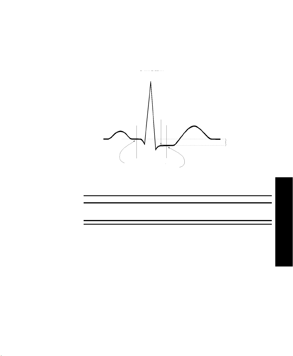
ST/AR ST Algorithm
The Measurement
The ST measurement for each beat complex is the vertical difference between
two measurement points. The isoelectric point provides the baseline for the
measurement and the ST point provides the other measurement point. It is
positioned with reference to the J-point.
R-WAVE PEAK
AT 0 MSEC
P
ISO ELECTRIC
POINT
DEFAULT =
-80 MSEC
J POINT
Q
S
MEASUREMENT
DEFAULT =
J+60 MSEC
ST
POINT
T
DIFFERENCE =
ST VALUE
Warning
This device provides ST level change information; the clinical significance
of the ST level change information should be determined by a physician.
3 ST Monitoring
ST/AR ST Segment Monitoring
3-3
Page 64

ST/AR ST Algorithm
How the Algorithm Works
Displayed ST Data
When ST analysis is being performed on two leads, the averaged derived and
reconstructed ST waves and associated ST segment values are given for up to
six leads, depending on the type of patient cable:
• 3-wire: one lead
• 5-wire: up to two leads if monitoring a chest and a limb lead
• 5-wire: up to six leads if monitoring two limb leads with the Philips
Transmitter (without EASI monitoring)
• 5- wire: up to 12 leads if monitoring using EASI
Note—No ST analysis is done on a patient if an electrode falls off.
ST analysis uses the ST/AR arrhythmia beat classification to select only normal
and atrially paced beats for its analysis.
The ST/AR ST algorithm processing includes special ST filtering, beat selection
and statistical analysis, calculation of ST segment elevations and depressions,
and lead reconstruction and wave generation.
ST data displays as values in the Patient Sector and Patient Window. A positive
value indicates ST segment elevation; a negative value indicates depression.
You can view ST data in ST Review, Trend Review, and Event Review
windows.
EASI ST Analysis
ST/AR ST analysis for EASI derived transmitters is done on all 12 leads. The
value presented in the patient sector and Patient Window is “STindx”. STindx is
a summation of three ST segment measurements, using the leads that can
1
2
3
4
5
indicate ST segment changes in the different locations of the heart:
• anterior lead V2
• lateral lead V5
EASI
• inferior lead aVF
Caution
Be sure not to duplicate the lead labels. This can result in incorrect ST values
being displayed for those leads.
3-4 ST/AR ST Segment Monitoring
Page 65
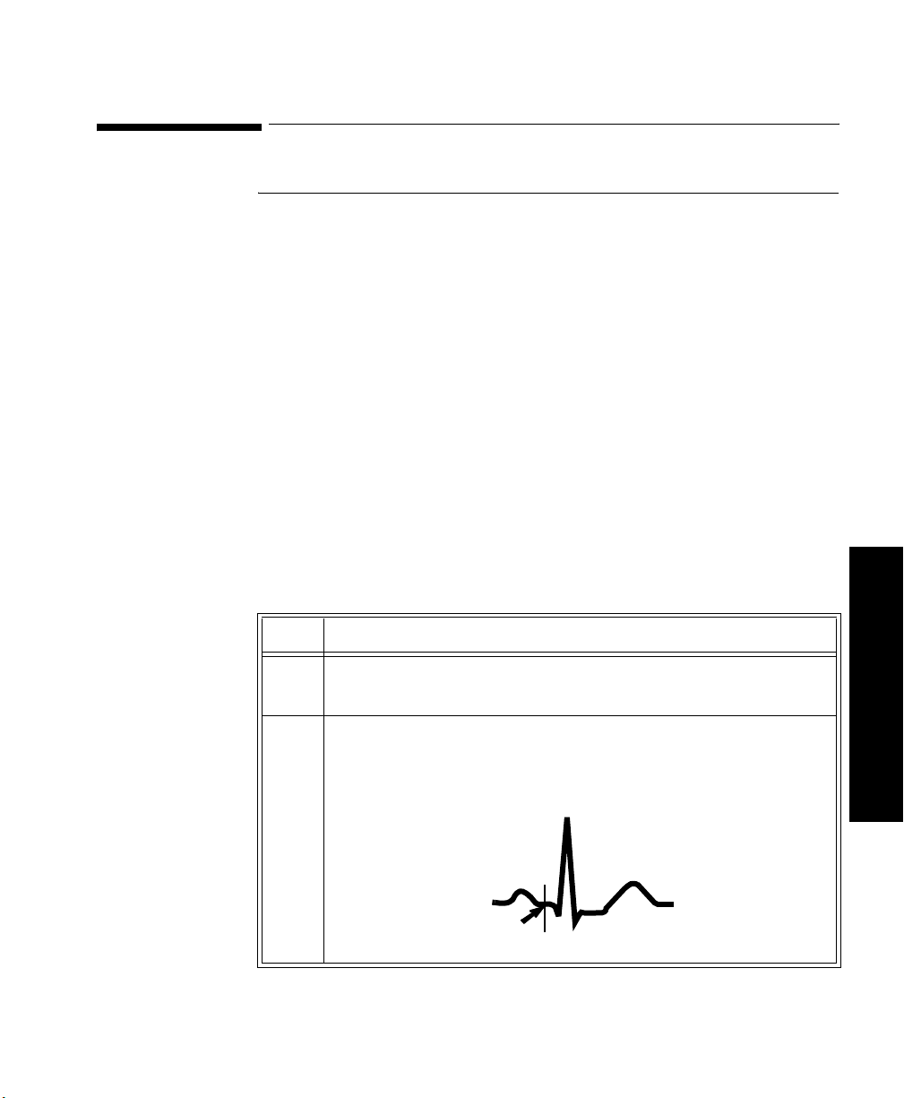
Adjusting Measurement Points
Adjusting Measurement Points
Overview The ST Setup Window allows you to adjust the ST measurement points to
ensure accurate data.
There are three measurement cursors:
• The ISO measurement cursor positions the isoelectric point in relation to
the R-wave peak.
• The J-point cursor positions the J-point in relation to the R-wave peak.
The purpose of the J-point is to correctly position the ST measurement
point.
• The ST measurement cursor positions the ST point a fixed distance from
the J point.
Note—The ST measurement points may need to be adjusted if the patient's heart
rate or ECG morphology changes significantly.
Task Summary
Perform the following steps to adjust the ST measurement points:
Step
Action
1 Access the ST Setup window by clicking on the All Controls button
in the Patient Window then clicking on the
ST Setup button.
2 If you need to adjust the ISO (isoelectric) point, position the bar in
the middle of the flattest part of the baseline (between the P and Q
waves or in front of the P wave) and use the arrow keys to make the
adjustment.
R
T
ISO
point
P
Q
S
ST/AR ST Segment Monitoring
3 ST Monitoring
3-5
Page 66

Adjusting Measurement Points
Step
Action
3 Adjust the J point, if necessary, by positioning the bar at the end of
the QRS complex and the beginning of the ST segment.
R
P
SQJ point
T
4 Adjust the ST point, if necessary, by using the J point as an
“anchor” and using either J + 60 or J + 80 so that the bar is at the
midpoint of the ST segment.
R
P
Q
S
T
ST point
3-6 ST/AR ST Segment Monitoring
Page 67

Establishing ST Reference Beats (Baseline)
Establishing ST Reference Beats (Baseline)
After adjusting the measurement points, you can establish baseline reference
beats for all available leads in the ST Review window at the Philips Information
Center. Reference beats enable you to compare waveform changes, for example
from admission, or prior to or after treatment. The reference continues to be
saved beyond the 24 hour review window, but you can update it to any beat
within the last 24 hours. Please refer to the Philips Information Center User’s
Guide or on-line Help for directions.
Turning ST On/Off
Overview The ST Setup Window allows you to turn ST monitoring on/off for all available
ECG leads. You would turn ST monitoring off if:
• You are unable to get any lead that is not noisy.
• Arrhythmias such as atrial fib/flutter cause irregular baseline.
• The patient is continuously ventricularly paced.
• The patient has left bundle branch block.
3 ST Monitoring
Task Summary
To turn ST monitoring on/off perform the following steps:
Step
Action
1 Access the ST Setup Window by clicking the All Controls button on
the Patient Window then clicking the
2 If you want to turn all ST monitoring on/off click
ST Setup button.
ST On.
ST/AR ST Segment Monitoring
3-7
Page 68

ST Alarms
ST Alarms
Overview All Philips Information Center alarm settings (limits and on/off status) have unit
default settings. The Philips Information Center however, lets you set the high
and low ST alarm limits for individual patients based on:
• Your assessment of the patient's clinical condition.
• Unit protocols.
• Physician orders or medication specified limits.
You can make the following adjustments to ST alarm limits to accommodate the
clinical condition of individual patients:
• Turn all alarms off/on.
• Adjust the alarm limits:
– to specific high and low limits
– to Smart Limits (see the Philips Information Center User’s Guide for
information on Smart Limits)
– back to unit default settings.
You adjust the ST alarm limits in the ST Alarms Window. Each ST parameter
has its own alarm limit. The alarm is triggered when the ST value exceeds its
alarm limit for more than 1 minute. The alarm will be a yellow alarm.
When more than one ST parameter is in alarm, only one alarm message displays.
For multilead alarms when using an EASI transmitter, an alarm is generated if
two or more ST leads exceed the alarm limits. The default setting is +/-1.0. The
alarm message indicates the two leads that are in greatest violation of the limits,
for example, “**MULTI ST AVR, V6”. If another lead becomes deviant, the
message changes but it is considered the same alarm (no new alarm sounds and
it is not listed as a new event).
Note—See the Philips Information Center User’s Guide for specifics on alarm
management and behavior.
3-8 ST/AR ST Segment Monitoring
Page 69

ST Alarms
ST Alarm Adjustments
Make adjustments to ST alarms on the ST Alarms window.
Step
Action
1 Access the ST Alarms window by clicking on the All Controls
button in the Patient Window then clicking the ST Alarms button
under Alarm Management and Setup.
2 Make the adjustments on the ST Alarms window. Choices for setting
the ST alarm limits are:
Unit Settings—Click on this button if want to have the specific
limits that are pre-set for your unit.
Smart Limits—Click on this button to set high and low limits around
your patient's current ST value. The difference above and below the
patient's ST value are pre-set for your unit.
Note—Smart Limits can be configured to automatically be activated
when the patient is connected. See the Philips Information Center
User’s Guide for additional information on using smart limits.
Specified limits—Use these to set the high and low alarm limits
based on your assessment of the patient's clinical condition, unit
protocols, or physician orders or medication specified limits. A good
guideline is + 1.0 mm or - 1.0 mm from the patient's ST, or follow
your unit protocol.
3 ST Monitoring
ST/AR ST Segment Monitoring
3-9
Page 70

ST Alarms
ST Alarm and INOP Summary
Message Level Sound Description
** STx > nnn Yellow Continuous ST (for lead x) greater than the upper limit (nnn)
** STx < nnn Yellow Continuous ST (for lead x) lower than the lower limit (nnn)
**MULTI ST x,y Yellow Continuous Two or more ST leads exceed the alarm limits.
The following table lists the ST alarm messages and the description of the
conditions required to generate these alarms. These alarms are not active when
arrhythmia/ST monitoring is turned off at the Philips Information Center. In the
table below:
x = ST lead
y= ST lead when multilead
nnn = limit that was exceeded.
The default setting is +/-1.0. The alarm message
indicates the two leads (x, y) that are in greatest
violation of the limits. For EASI only.
The following table lists the ST INOP messages
Note—A Hard INOP indicates a more severe situation than a soft INOP. Hard
INOPS have an audible tone, and monitoring and alarms are disabled. In a soft
INOP, no audible tone is generated; monitoring and alarms remain active.
Message Type Description Action
CANNOT
ANALYZE ST
3-10 ST/AR ST Segment Monitoring
Soft INOP
(No sound)
The algorithm cannot
generate a valid ST value
because:
• the variation between
measured ST values
exceeded the limits for
valid data, or
• the algorithm cannot
reliably analyze the ST
data on any monitored
leads.
Review the ECG signal
quality and correct if
necessary. Reposition the
Iso and J points.
Page 71

4
SpO
This chapter provides an introduction to the SpO2 measurement and its
application. It includes the following sections:
• Overview. . . . . . . . . . . . . . . . . . . . . . . . . . . . . . . . . . . . . . . . . . .4-2
• Preparing for Telemetry SpO
• Making SpO
• Measurement Limitations . . . . . . . . . . . . . . . . . . . . . . . . . . . . . .4-8
•SpO
• Selecting the Appropriate Transducer . . . . . . . . . . . . . . . . . . .4-10
• Applying the Transducer. . . . . . . . . . . . . . . . . . . . . . . . . . . . . .4-11
• Optimizing Transducer Performance . . . . . . . . . . . . . . . . . . . .4-16
• Turning the SpO
• Turning SpO
• Turning the Pulse Parameter On/Off . . . . . . . . . . . . . . . . . . . .4-19
•SpO
Transducers . . . . . . . . . . . . . . . . . . . . . . . . . . . . . . . . . . .4-9
2
Alarm and INOP Summary . . . . . . . . . . . . . . . . . . . . . . .4-20
2
Measurements . . . . . . . . . . . . . . . . . . . . . . . . . . .4-6
2
Parameter On/Off . . . . . . . . . . . . . . . . . . . .4-17
2
Alarms On/Off . . . . . . . . . . . . . . . . . . . . . . . . . .4-19
2
Monitoring . . . . . . . . . . . . . . . . .4-4
2
Monitoring
2
SpO2 Monitoring 4-1
4 SpO
2
Monitoring
Page 72

Overview
Overview
The SpO2 parameter measures the arterial oxygen saturation. That is, the
percentage of oxygenated hemoglobin in relation to the total hemoglobin.
If, for example, a total of 97% of the hemoglobin molecules in the red blood
cells of the arterial blood combine with oxygen, then the blood has an oxygen
saturation of 97%. The SpO
97%. The SpO
numeric indicates the percentage of hemoglobin molecules
2
numeric that appears on the monitor will read
2
which have combined with oxygen molecules to form oxyhemoglobin.
• The oxygen saturation is measured using the pulse oximetry method. This
is a continuous, noninvasive method of measuring the arterial hemoglobin
oxygen saturation. It measures how much light, sent from light sources on
one side of the transducer, travels through patient tissue (such as a finger
or an ear), to a receiver on the other side.
• The amount of light getting through depends on many factors, most of
which are constant, such as tissue or venous blood). However one of the
factors, the blood flow in the arterioles, varies with time - because it is
pulsatile.
4-2 SpO
Monitoring
2
This measurement principle is used to derive the SpO
measurement. The
2
numeric that is displayed at the Philips Information Center is the oxygen
saturation of the arterial blood - the measurement of light absorption
during a pulsation.
Page 73

Overview
Warning
When the specified Nellcor® transducers are used, the application must be
consistent with the manufacturer's own guidelines.
Prolonged, continuous monitoring may increase the risk of changes in skin
characteristics, such as irritation, reddening, blistering or pressure
necrosis, particularly on patients with impaired perfusion and varying or
immature skin morphology. Specific attention must be given to sensor site
inspection for changes in skin quality, proper optical path alignment and
attachment. Check the application site at regular intervals and change the
site if any compromise in skin quality should occur. More frequent
checking may be required due to an individual patient's condition.
Setting the high SpO
alarm limit to 100% is equivalent to switching off the
2
high alarm limit. Therefore the upper alarm limit for oxygen saturation
must be carefully selected in accordance with accepted clinical practices.
Pulse oximetry can overestimate the SpO
value in the presence of Hb-CO,
2
Met-Hb or dye dilution chemicals.
Note—The SpO
alarm delay built into the system is ten seconds. That means
2
that the monitor generates an alarm if the averaged numeric value on the display
stays beyond the alarm limit for more than 10 seconds.
4 SpO
2
Monitoring
Monitoring 4-3
SpO
2
Page 74

Preparing for Telemetry SpO2 Monitoring
Preparing for Telemetry SpO2 Monitoring
Overview The Philips Telemetry System provides remote monitoring of SpO
measurement for adult and pediatric patients. You need to prepare your
telemetry patient and perform setup tasks for the measurement to display at the
Philips Information Center, the Wave Viewer, or the TeleMon.
Task
Perform the following steps to set up for telemetry SpO2 monitoring:
Summary
Step
Action
1 Select the site and appropriate transducer (see “Selecting the
Appropriate Transducer” on page 4-10).
• Adult Finger - use for most adults.
• Small Adult/Pediatric - use for small adults.
• Ear Clip - use when neither hand has an appropriate site.
2 Attach the transducer cable to the transmitter.
Plug reusable transducers directly into the transmitter.
Plug disposable transducers into the adapter cable, then plug the
adapter cable into the transmitter.
2
4-4 SpO
Monitoring
2
Page 75

Preparing for Telemetry SpO2 Monitoring
Step
Action
3 Prepare the transducer (if disposable, remove the protective
backing), and attach the transducer to the appropriate part of the
patient's body.
Avoid sites with:
• Decreased Arterial Flow, such as edematous tissue or distal
to arterial catheters, intravenous catheters and blood pressure
cuffs
• Poor Skin Integrity, such as skin discoloration or nail polish.
• Excessive Motion
Additionally, avoid:
• Placing the sensor in an environment with bright lights. If
necessary, cover the sensor with opaque material.
• Use of excessive pressure at the application site, for example,
transducer applied too tightly, excessive adhesive tape to
secure the transducer, clothing or restraints that are too tight.
These result in venous pulsations and inaccurate
measurements, and may severely obstruct circulation.
4 Use the pleth wave to check the signal quality at the patient’s side
using the Wave Viewer or the TeleMon.
5 Adjust SpO
alarms in the Patient Window.
2
6 Make other adjustments in the Telemetry Setup Window.
7 Inspect the site regularly to ensure skin integrity and correct optical
alignment. Proper sensor placement is critical to accurate SpO
2
monitoring.
Monitoring 4-5
SpO
2
4 SpO
2
Monitoring
Page 76

Making SpO2 Measurements
Making SpO2 Measurements
SpO2 measurements can be made automatically at pre-determined times, or
manually on an as-needed basis.
Automatic Measurements
Automatic SpO
measurements can be generated on a continuous basis, or
2
intermittently at 1 or 5 minute intervals. Automatic measurement intervals are
set at the Wave Viewer or the TeleMon. Please see “Changing the SpO
Rate” on page E-10 to set up the transmitter for automatic measurements.
Procedures for the TeleMon can be found in the TeleMon B Monitor
Instructions for Use on page 3-7.
Manual Measurements
Manual measurements can be initiated at the transmitter or at Wave Viewer.
SpO
must be turned on at central for alarms, and for display and trending. For
2
measurements at the transmitter or Wave Viewer, the sample rate must be set to
any choice except “Continuous”.
To initiate an SpO
measurement at Wave Viewer, see “Making a STAT SpO2”
2
on page E-11.
If you have a TeleMon, see the TeleMon Instructions for Use, page 3-7.
Note—The Wave Viewer should not be connected to the transmitter when you
are using the transmitter button to initiate an SpO
Task Summary To initiate a manual SpO
steps.
Step Action
Sample
2
measurement.
2
measurement at the transmitter, perform the following
2
4-6 SpO
Monitoring
2
1 Plug the transducer cable into the transmitter.
2 Attach the transducer to the patient.
3 Press and hold (~6 seconds) the Transmitter Button until the LA
(standard ECG) or S (EASI) light begins flashing.
Page 77

Making SpO2 Measurements
Step Action
4 When the transducer light turns off (~ 30 seconds later), the
measurement value and time stamp will be displayed at central for
up to one hour or until the next measurement is made, whichever
comes first.
5 Remove the transducer from the patient after the transducer light
goes out.
Note—When an SpO
measurement is initiated, if the transmitter button is
2
turned ON in the Patient Window, the transmitter button will also function
according to its function defined during system configuration. For example, if
the patient button is configured for Nurse Call/Record or Record, a recording
will be generated when a manual SpO
recording will include the last SpO
reading is initiated at the transmitter. The
2
reading, but not the current reading, which
2
is still in process.
Note—If the transmitter button is turned OFF in the Patient Window, a manual
SpO
measurement can still be made.
2
Note—No measurement will be made if a Battery Weak condition exists. A
measurement initiated before a Battery Weak INOP is displayed will be
completed, but no further manual measurements can be made until the battery is
replaced.
Note—If a LEADS OFF condition occurs during a manual SpO
measurement,
2
the appropriate lead light will be lit upon completion of the measurement.
Monitoring 4-7
SpO
2
4 SpO
2
Monitoring
Page 78

Measurement Limitations
Measurement Limitations
Refer to this section on problem situations if you have difficulty getting a signal
or obtaining accurate measurements.
Distortion
Ambient light, motion, perfusion or incorrect sensor placement may affect the
accuracy of the derived measurements.
Arterial Blood Flow
The measurement depends on the pulsatile nature of blood flow in the arteries
and arterioles; with the following conditions arterial blood flow may be reduced
to a level at which accurate measurements cannot be made:
•shock
• hypothermia
• use of vasoconstrictive drugs
•anemia
Wavelength Absorption
The measurement also depends on the absorption of particular light wavelengths
by the oxyhemoglobin and reduced hemoglobin. If other substances are present
which absorb the same wavelengths, they will cause a falsely high, or falsely
low SpO
• carboxyhemoglobin
• methemoglobin
• methylene blue
• indocyanine green*
• indiocarmine*
*These chemicals are used in dye dilution cardiac output calculations.
value to be measured. For example:
2
4-8 SpO
Monitoring
2
Ambient Light
Very high levels of ambient light can also affect the measurement; an SpO
2
INTERFERENCE message will appear on the display. The measurement quality
can be improved by covering the transducer with suitable non see-through
material.
Note—If you are using Nellcor® transducers, see the directions for use supplied
with these transducers.
For care and cleaning instructions, see “Philips Reusable Transducers” on page
5-19.
Page 79

SpO2 Transducers
SpO2 Transducers
Disposable Transducers
Reusable Transducers
Only use disposable transducers once and then discard. However, you can
relocate them to a different patient-site if the first location does not give the
desired results. Do not reuse disposable transducers on different patients.
Disposable transducers are not available as Philips Medical Systems parts in the
USA or Canada. Contact Nellcor® Incorporated at 1-800-635-5267 or 1-888744-1414.
You can use reusable transducers on different patients after cleaning and
disinfecting them. See “Philips Reusable Transducers” on page 5-19 for cleaning
instructions. Reusable sensors should be changed to another site regularly.
See Appendix B, “Accessories and Ordering Information” for ordering
information.
Monitoring 4-9
SpO
2
4 SpO
2
Monitoring
Page 80

Selecting the Appropriate Transducer
Selecting the Appropriate Transducer
The following chart provides a guideline to select the most appropriate
transducer for your patient.
Select the most appropriate transducer by finding the patient's weight on the
vertical axis, and drawing a horizontal line across the chart. Each shaded area
that the line passes through represents a transducer that you can use on this
patient.
Areas of dark shading indicate that the transducer is the most appropriate one in
that weight range.
Areas of light shading indicate that you can use the transducer in this weight
range, even though it is not the most appropriate transducer.
Greater
than
Adult
Finger
50 kg
50
40
Clip
4-10 SpO
Monitoring
2
Preferred
Transducer
Alternative
Transducer
Finger
Small Adult/Pediatric
30
20
15
10
2.5
3
1
D-20 D-25 M1192A
Disposable
Transducers
100x140
M1191A M1194A
Reusable Transducers
Page 81

Applying the Transducer
Applying the Transducer
Overview A minimum pulsatile flow must be present at the application site of your patient
to obtain measurements.
Select an appropriate transducer and apply the transducer properly to avoid
incorrect measurements. Applying a small amount of pressure at the application
site can improve the measurement. Use one of the preferred application sites for
your transducer. Selecting the most suitable transducer and application site will
help you to ensure that:
• The light emitter and the photodetector are directly opposite each other
and that all the light from the emitter passes through the patient's tissues,
• The application site is of the correct thickness for light to pass through. If
the application site is too thick or too thin, an SpO
INOP will occur. You should then select another site as appropriate.
NON-PULSATILE
2
Light Source
Photo detector
Positioning of the Light Emitters and Photodetector
Inspect the application site every 2 to 3 hours to ensure skin integrity and correct
optical alignment. If skin integrity changes, move the transducer to another site.
Monitoring 4-11
SpO
2
4 SpO
2
Monitoring
Page 82

Applying the Transducer
Warnings • Failure to apply the transducer properly may cause incorrect
measurement of SpO
• Specific attention must be given to sensor site inspection for changes
in skin quality, proper optical path alignment and attachment. Check
the application site at regular intervals and change the site if any
compromise in skin quality should occur.
• Using a transducer during MR imaging can cause severe burns. To
minimize this risk, ensure that the cable is positioned so that no
inductive loops are formed. If the transducer does not appear to be
operating properly, remove it immediately from the patient.
• Using a transducer in the presence of bright lights may result in
inaccurate measurements. In such cases, cover the site with opaque
material.
• Injected dyes, such as methylene blue, or intravascular
dyshemoglobins, such as methemoglobin, may lead to inaccurate
measurements.
• Performance may be compromised by excessive motion. This can lead
to inaccurate SpO
.
2
readings.
2
4-12 SpO
Monitoring
2
• Avoid placing the SpO
transducer on any extremity with an arterial
2
catheter, or intravascular venous infusion line.
• Do not use disposable transducers on patients who exhibit allergic
reactions to the adhesive.
Page 83

Applying the Transducer
Adult Finger Transducer (M1191A)
Push the transducer over the fingertip in such a way that the fingertip touches
but does not protrude from the end of the transducer. The fingernail must be
uppermost and the cable must lie on the back of the hand. This ensures that the
light sources cover the base of the fingernail giving the best measurement
results. The cable can be held in place by the accompanying wristband.
Warning
Failure to apply the transducer properly may cause incorrect measurement
of SpO
finger can result in inaccurate SpO
. For example, not pushing the transducer far enough over the
2
readings. Pushing the transducer too
2
far, so that the finger protrudes from the transducer, can pinch the finger,
resulting in inaccurately low SpO2 readings.
Monitoring 4-13
SpO
2
4 SpO
2
Monitoring
Page 84

Applying the Transducer
Small Adult/ Pediatric Finger Transducer (M1192A)
Push the transducer over the fingertip in such a way that the fingertip touches
but does not protrude from the end of the transducer.
Warning
Failure to apply the transducer properly may reduce the accuracy of the
SpO2 measurement.
4-14 SpO
Monitoring
2
Page 85

Applying the Transducer
Ear Clip Transducer (M1194A)
Clip the probe onto the fleshy part of the ear lobe as shown in the diagram
below. The plastic fixing mechanism helps to minimize artifact generated by
patient motion. Do not position the probe on cartilage or where it presses against
the head.
The clip transducer can be used as an alternative if the adult finger transducer
does not provide satisfactory results. The preferred application site is the ear
lobe, although other application sites with higher perfusion (such as the nostril)
can be used. Due to the physiologically lower perfusion in the ear lobe, you
should be aware of the reduced accuracy of the measurement and more frequent
INOPs.
Warning
Failure to apply the clip transducer properly may reduce the accuracy of
the SpO2 measurement.
Disposable Transducers
See the Directions for Use supplied by Nellcor® Incorporated for instructions on
preparation and application of disposable transducers.
Warning
When the specified Nellcor® transducers are used, the application must be
consistent with the manufacturer's own guidelines.
Monitoring 4-15
SpO
2
4 SpO
2
Monitoring
Page 86

Optimizing Transducer Performance
Optimizing Transducer Performance
To get the best results from your SpO2 reusable transducer:
• Always handle the transducer and cable with care. The soft finger sleeve
houses a sensitive electronic device that can be damaged by harsh
treatment. Always protect the cable from sharp-edged objects.
• Use the wristband that is supplied with your M1191A transducer. By
keeping the cable between the finger transducer and the wristband fairly
loose, you will maintain good monitoring conditions.
Normal wear and tear associated with patient movement and regular transducer
cleaning naturally mean that your transducer will have a limited lifetime.
However, provided you handle the transducer and its cable with care, you can
expect useful service from it for up to two years. Harsh treatment will drastically
reduce the lifetime of the transducer. Moreover, Philips Medical Systems’
warranty agreement shall not apply to defects arising from improper use.
4-16 SpO
Monitoring
2
Page 87

Turning the SpO2 Parameter On/Off
Turning the SpO2 Parameter On/Off
Overview The SpO
using the Telemetry Setup Window.
Turning the SpO
•SpO
•SpO
•SpO
After you turn SpO
patient’s acuity by using the Wave Viewer or the TeleMon.
After you turn SpO
Viewer or the TeleMon will help you conserve the transmitter’s battery life.
SpO
2
Parameter
Auto ON
The SpO
if a manual SpO
mode or the SpO
is in continuous SpO
When a patient is discharged and the transmitter is in Continuous mode, the
SpO
parameter is turned off. To reactivate the SpO2 parameter Auto ON
2
feature from the transmitter, remember to do one of the following when a patient
is discharged:
parameter is turned on or off at the Philips Information Center by
2
parameter off at the Information Center also turns off:
2
alarms
2
display of numerics
2
trending.
2
on, you should adjust the sample rate to match your
2
off, setting the sample rate to Manual using the Wave
2
parameter is automatically turned on at the Philips Information Center
2
– remove the SpO
measurement is initiated at the transmitter while in Manual
2
transducer is inserted into the transmitter while the transmitter
2
mode.
2
cable from the transmitter, wait 15 seconds, then
2
reinsert the cable
or
– reset the transmitter to Manual mode.
Note—The SpO
parameter Auto ON feature only needs to be reactivated when
2
the transmitter is in Continuous mode at discharge.
Note— SpO
can always be turned on and off at the Philips Information Center.
2
Monitoring 4-17
SpO
2
4 SpO
2
Monitoring
Page 88

Turning the SpO2 Parameter On/Off
Task Summary
Turn the SpO2 parameter on or off manually by performing the following steps:
Step
Action
1 On the Patient Window click the All Controls button.
2 On the All Controls Window click the
3 On the Telemetry Setup Window, turn SpO
clicking in the
checkbox indicates that SpO
Parameter ON checkbox. A check mark in the
monitoring is on.
2
Telemetry Setup button.
parameter on or off by
2
4-18 SpO
Monitoring
2
Page 89

Turning SpO2 Alarms On/Off
Turning SpO2 Alarms On/Off
Overview You can turn SpO
Task
Turn SpO2 alarm on or off by performing the following steps:
alarms on or off by using the Telemetry Setup Window.
2
Summary
Step Action
1 On the Patient Window click the
2 On the All Controls Window click the
3 On the Telemetry Setup Window turn SpO
clicking in the
indicates that SpO
Alarm ON checkbox. A check mark in the checkbox
alarms are on.
2
Turning the Pulse Parameter On/Off
Overview You can turn the SpO
Window.
Task
Turn the pulse parameter on or off by performing the following steps:
Summary
Step Action
pulse parameter on or off by using the Telemetry Setup
2
All Controls button.
Telemetry Setup button.
alarms on or off by
2
1 On the Patient Window click the
2 On the All Controls Window click the
3 On the Telemetry Setup turn pulse parameter on or off by clicking
in the
Parameter ON checkbox. A check mark in the checkbox
indicates that pulse monitoring is on.
All Controls button.
Telemetry Setup button.
Monitoring 4-19
SpO
2
4 SpO
2
Monitoring
Page 90

SpO2 Alarm and INOP Summary
SpO2 Alarm and INOP Summary
SpO2 alarms are non-latching. That is, when an SpO2 limit is exceeded, if the
alarm is not silenced, it will reset automatically if the patient’s alarm condition
returns within the limits. This reduces the number of times you will need to reset
alarms at the information center when an alarm condition has been corrected at
the patient’s side (for example, movement-induced artifact alarms).
The following table lists the SpO
alarms and the description of the conditions
2
required to generate these alarms.
Message Level Sound Description
**SpO
> upper limit Yellow Continuous SpO2 value greater than the upper SpO2
2
measurement limit.
Important—Setting the high SpO
100% is equivalent to switching off the high
alarm.
**SpO
< low limit Yellow Continuous SpO2 value less than the lower SpO2
2
measurement limit.
alarm limit to
2
4-20 SpO
Monitoring
2
Page 91

SpO2 Alarm and INOP Summary
The following table lists the SpO2 INOPs. The Action column includes
recommendations on what to do when one of these INOPs occurs.
Note—A Hard INOP indicates a more severe situation than a soft INOP. Hard
INOPS have an audible tone, and monitoring and alarms are disabled. In a soft
INOP, no audible tone is generated; monitoring and alarms remain active.
Message Type Description Action
SpO
EQUIP MALF Hard INOP Malfunction in the SpO
2
2
Change transducer.
hardware, or transducer/
adapter cable damaged
Change adapter cable.
If INOP persists, replace
transmitter.
SpO
ERRATIC Hard INOP Erratic SpO2 measurements,
2
often due to a faulty
transducer or incorrect
positioning of the transducer
May also be caused by
optical shunting if sensor too
big or too small.
Line up light source and
photo detector - they must
be opposite each other and
light must pass through the
arteriolar bed.
Reposition transducer to
site with higher perfusion.
Replace transducer or
adapter cable.
Use different sensor with
correct fit.
4 SpO
2
Monitoring
Monitoring 4-21
SpO
2
Page 92

SpO2 Alarm and INOP Summary
Message Type Description Action
SpO2
INTERFERENCE
SpO
NO
2
TRANSDUCER
Hard INOP Level of ambient light is so
high that the SpO
cannot measure SpO
transducer
2
or
2
pulse rate.
Transducer or adapter cable
is damaged.
May also be due to electrical
interference.
May also be generated by a
defective transmitter.
Hard INOP SpO2 transducer is
disconnected.
connector on
SpO
2
transducer or transmitter is
dirty.
Cover sensor with nonwhite opaque material (for
example, pulse oximeter
probe wraps - Posey wrap
or equivalent) to reduce
ambient light.
If INOP persists, inspect
and replace transducer or
adapter cable as needed.
Reduce sources of
electrical interference.
If the above corrective
actions are ineffective, use
a different transmitter, and
call service to replace the
defective one.
Reconnect sensor.
Replace sensor.
Replace transmitter and
call service.
SpO
NOISY
2
SIGNAL
4-22 SpO
Monitoring
2
Hard INOP Excessive patient movement
or electrical or optical
interference is causing
irregular pulse patterns
Locate sensor at site with
less movement.
Reduce sources of
electrical or optical
interference.
Call service.
Page 93

SpO2 Alarm and INOP Summary
Message Type Description Action
SpO
NON-
2
PULSATILE
Hard INOP Pulse too weak or not
detectable
Relocate sensor to site with
improved circulation.
Warm area to improve
May also be generated by a
circulation.
defective transmitter.
Try another sensor type.
If the above corrective
actions are ineffective, use
a different transmitter, and
call service to replace the
defective one.
SpO
TRANS
2
MALFUNC
Hard INOP The SpO2 transducer is
malfunctioning.
connector on the
SpO
2
transducer or transmitter is
dirty or corroded.
Replace the transducer or
adapter cable.
Change the transmitter and
call service to repair.
4 SpO
2
Monitoring
Monitoring 4-23
SpO
2
Page 94

SpO2 Alarm and INOP Summary
4-24 SpO
Monitoring
2
Page 95

Telemetry System Cleaning
This chapter describes cleaning of the telemetry equipment. It includes the
following sections:
• Cleaning and Disinfection . . . . . . . . . . . . . . . . . . . . . . . . . . . . . . . . 5-2
• Cleaning the Receiver Mainframe . . . . . . . . . . . . . . . . . . . . . . . . . .5-3
• Cleaning the Transmitter & Battery Extender . . . . . . . . . . . . . . . . .5-4
• Cross-infection Prevention for the Transmitter & Battery Extender 5-8
• Cleaning the Hewlett-Packard 200LX Palmtop Computer . . . . . .5-15
• Cleaning ECG Patient Cables and Leads . . . . . . . . . . . . . . . . . . .5-16
• Cleaning SpO
Adapter Cable & Transducers . . . . . . . . . . . . . . .5-18
2
5 Cleaning
5
Telemetry System Cleaning 5-1
Page 96

Cleaning and Disinfection
Cleaning and Disinfection
Warning
To prevent fire, provide adequate ventilation and do not permit smoking
when cleaning the transmitter or the receiver mainframe with a flammable
liquid, such as alcohol, or sterilizing with ethylene oxide (EtO).
Disconnect line power from the receiver mainframe to prevent electrical
shock and accidental turn-on.
Caution
Do not use any abrasive cleaning materials on any part or component of the
Philips Telemetry System.
Do not clean any part or component of the Philips Telemetry System in any
overly vigorous or abrasive fashion.
Using abrasive cleansers and abrasive cleaning actions will damage the
components.
5-2 Telemetry System Cleaning
Page 97

Cleaning the Receiver Mainframe
The receiver mainframe should be kept free of dust and dirt. You can only clean
the outside of the receiver mainframe. Wipe the outside of the receiver
mainframe clean by wetting a damp cloth or rag with one of the following
approved cleaning agents:
• Soap and Water
Cleaning the Receiver Mainframe
5 Cleaning
• Isopropyl Alcohol (>
• Ethyl Alcohol (>
• Hydrogen Peroxide
• Sodium Hypochlorite (chlorine bleach), 5% solution
• Sodium Hypochlorite (chlorine bleach), 10% solution prepared within
24 hours
•Cidex®
• Windex®
• Lysol®
Wipe all cleaned surfaces with distilled water to remove any residue. Allow to
air-dry, or dry with a non-lint producing cloth before use.
70%)
70%)
Telemetry System Cleaning
5-3
Page 98

Cleaning the Transmitter & Battery Extender
Cleaning the Transmitter & Battery Extender
The outside of the transmitter and battery extender should be kept free of dirt
and dust.
The transmitter and battery extender can be cleaned by two methods: wiping or
soaking.
Caution
Remove the battery and any cables or accessories before you clean and/or soak
the transmitter.
Wiping the Transmitter Exterior
Task Summary Wipe the outside of the transmitter by performing the following steps:
Step Action
1 Remove the battery and any cables or accessories.
2 Wipe the outside of the transmitter clean by using a cloth dampened
5-4 Telemetry System Cleaning
modestly with one of the following approved cleaning agents:
• Isopropyl Alcohol (>
• Ethyl Alcohol (>
• Hydrogen Peroxide, 3% solution
• Sodium Hypochlorite (chlorine bleach), 5% solution
• Sodium Hypochlorite (chlorine bleach), 10% solution
prepared within 24 hours
• Antibacterial soap and water.
•Cidex®
•Windex®
• Lysol®
70%)
70%)
Page 99

Cleaning the Transmitter & Battery Extender
Step Action
3 Wipe all cleaned surfaces with distilled water to remove any
residue.
4 Allow to air-dry, or dry with a non-lint producing cloth.
5 Cleaning
Wiping the
Battery
Under normal operation, the battery compartment should not require frequent
cleaning. However, if it must be cleaned, follow the following procedure.
Compartment
Task Summary Wipe the battery compartment by performing the following steps:
Step Action
1 Remove the battery and any cables or accessories.
2 Wipe the battery compartment clean by using a cloth dampened
modestly with one of the following approved cleaning agents:
• Isopropyl Alcohol (>
• Ethyl Alcohol (>
• Hydrogen Peroxide, 3% solution
• Sodium Hypochlorite (chlorine bleach), 5% solution
• Sodium Hypochlorite (chlorine bleach), 10% solution
prepared within 24 hours
3 Wipe all cleaned surfaces with distilled water to remove any
residue.
4 Allow to air-dry, or dry with a non-lint producing cloth.
70%)
70%)
Caution
Do not use soap and water, Cidex®, Windex®, or Lysol® inside the battery
compartment. These cleansers will damage the battery compartment.
Telemetry System Cleaning
5-5
Page 100

Cleaning the Transmitter & Battery Extender
Wiping the
Battery
The battery extender should be removed from the transmitter and power source
before cleaning or disinfection.
Extender
Task Summary Wipe the battery extender by performing the following steps:
Step Action
1 Disconnect the power module from the power source, and
remove the cradle from the transmitter.
2 Wipe the battery extender with a cloth dampened modestly
with one of the following approved cleaning agents:
• Isopropyl Alcohol (>
• Ethyl Alcohol (>
• Hydrogen Peroxide, 3% solution
• Sodium Hypochlorite (chlorine bleach), 5% solution
• Sodium Hypochlorite (chlorine bleach), 10% solution
prepared within 24 hours
3 Wipe all cleaned surfaces with distilled water to remove any
residue.
4 Allow to air-dry, or dry with a non-lint producing cloth.
70%)
70%)
Caution
Do not use soap and water, Cidex®, Windex®, or Lysol® on the cradle, wires,
or aqua connector, because they will damage these parts of the extender.
5-6 Telemetry System Cleaning
 Loading...