

Philips TEA6845AH, TEA6845H Datasheet
INTEGRATED CIRCUITS
DATA SH EET
TEA6845AH; TEA6845H
New In Car Entertainment (NICE)
car radio
Product specification
File under Integrated Circuits, IC01
2001 Apr 12

Philips Semiconductors Product specification
New In Car Entertainment (NICE) car radio TEA6845AH; TEA6845H
CONTENTS
1 FEATURES
2 GENERAL DESCRIPTION
3 ORDERING INFORMATION
4 QUICK REFERENCE DATA
5 BLOCK DIAGRAM
6 PINNING
7 FUNCTIONAL DESCRIPTION
7.1 Oscillators
7.1.1 VCO
7.1.2 Crystal oscillator
7.1.3 PLL
7.2 FM signal channel
7.2.1 DAA
7.2.2 FM I/Q mixer
7.2.3 FM keyed AGC
7.2.4 FM IF amplifiers
7.2.5 FM demodulator
7.3 AM signal channel
7.3.1 AM tuner including mixer 1 and mixer 2
7.3.2 AM RF AGC and IF2 AGC
7.3.3 AM detector
7.3.4 AM AF or IF2 switch
7.3.5 AM noise detector and blanker
7.3.6 FM and AM level detector
7.4 Test mode
8 LIMITING VALUES
9 THERMAL CHARACTERISTICS
10 DC CHARACTERISTICS
11 AC CHARACTERISTICS
12 I2C-BUS PROTOCOL
12.1 I2C-bus specification
12.1.1 Test mode
12.1.2 Data transfer for the TEA6845
12.1.3 I2C-bus pull-up resistors
12.1.4 Frequency setting
12.2 I2C-bus protocol
12.2.1 Data transfer mode and IC address
12.2.2 Write mode: data byte 1
12.2.3 Write mode: data byte 2
12.2.4 Write mode: data byte 3
12.2.5 Write mode: data byte 4
12.2.6 Write mode: data byte 5
12.2.7 Write mode: data byte 6
12.2.8 Read mode: data byte 1
13 TEST AND APPLICATION INFORMATION
14 PACKAGE OUTLINES
15 SOLDERING
15.1 Introduction to soldering surface mount
packages
15.2 Reflow soldering
15.3 Wave soldering
15.4 Manual soldering
15.5 Suitability of surface mount IC packages for
wave and reflow soldering methods
16 DATA SHEET STATUS
17 DEFINITIONS
18 DISCLAIMERS
19 PURCHASE OF PHILIPS I2C COMPONENTS
2001 Apr 12 2

Philips Semiconductors Product specification
New In Car Entertainment (NICE) car radio TEA6845AH; TEA6845H
1 FEATURES
• FM mixer for conversion of FM RF from 65 to 108 MHz
to IF of 10.7 MHz; the mixer provides inherent image
rejection
• FM RF mixer can be set to receive weather band radio
up to 162.55 MHz; weather band radio flag output
• AM mixer 1 for conversion of AM RF to AM IF1 of
10.7 MHz
• LC tuner oscillator providing mixer frequencies for
FM mixer and AM mixer 1
• AM mixer 2 for conversion of AM IF1 to AM IF2 of
450 kHz
• Crystal oscillator providing mixer frequencies for
AM mixer 2andreferenceforsynthesizerPLL,IF count,
timing for Radio Data System (RDS) update and
reference frequency for car audio signal processor ICs
• FastsynthesizerPLLtuning system with local control for
inaudible RDS updating
• Timing function for RDS update algorithm and control
signal output for car audio signal processor ICs
(TEA688x, SAA77xx) or car radio integrated signal
processor IC (TEF6890H)
• Digital auto alignment circuit for conversion of
LC oscillator tuning voltage to controlled alignment
voltage of FM antenna tank circuit
• AGC PIN diode drive circuit for FM RF AGC; AGC
detection at FM mixer input; the AGC PIN diode drive
can be activated by the I2C-bus as a local or distance
function; AGC threshold is a programmable and keyed
function switchable via the I2C-bus
• FM IF linear amplifiers with high dynamic input range
• FM quadrature demodulator with automatic centre
frequency adjustment and Total Harmonic Distortion
(THD) compensation
• Level detector for AM and FM with temperature
compensated output voltage; starting point and slope of
level output is programmable via the I2C-bus
• AM RF PIN diode drive circuit; AGC threshold detection
at AM mixer 1 and IF2 AGC input; threshold is
programmable via the I2C-bus; AM IF2 AGC and
demodulator
• AM AF output switchable to provide AM IF2 for
AM stereo decoder
• AM noise blanker with blanking at AM IF2
• Several test modes available for fast IC and system
tests.
2 GENERAL DESCRIPTION
The TEA6845 is a single IC with car radio tuner for
AM and FM intended for microcontroller tuning with the
I2C-bus. It provides the following functions:
• AM double conversion receiver for LW, MW and SW
(31 m, 41 m and 49 m bands) with IF1 = 10.7 MHz and
IF2 = 450 kHz
• FM single conversion receiver with integrated image
rejection for IF = 10.7 MHz capable of selecting US FM,
US weather, Europe FM, East Europe FM and Japan
FM bands.
3 ORDERING INFORMATION
TYPE
NUMBER
TEA6845AH QFP64 plastic quad flat package; 64 leads (lead length 1.95 mm);
TEA6845H QFP64 plastic quad flat package; 64 leads (lead length 1.95 mm);
2001 Apr 12 3
NAME DESCRIPTION VERSION
body 14 × 20 × 2.8 mm
body 14 × 20 × 2.8 mm
PACKAGE
SOT319-5
SOT319-2

Philips Semiconductors Product specification
New In Car Entertainment (NICE) car radio TEA6845AH; TEA6845H
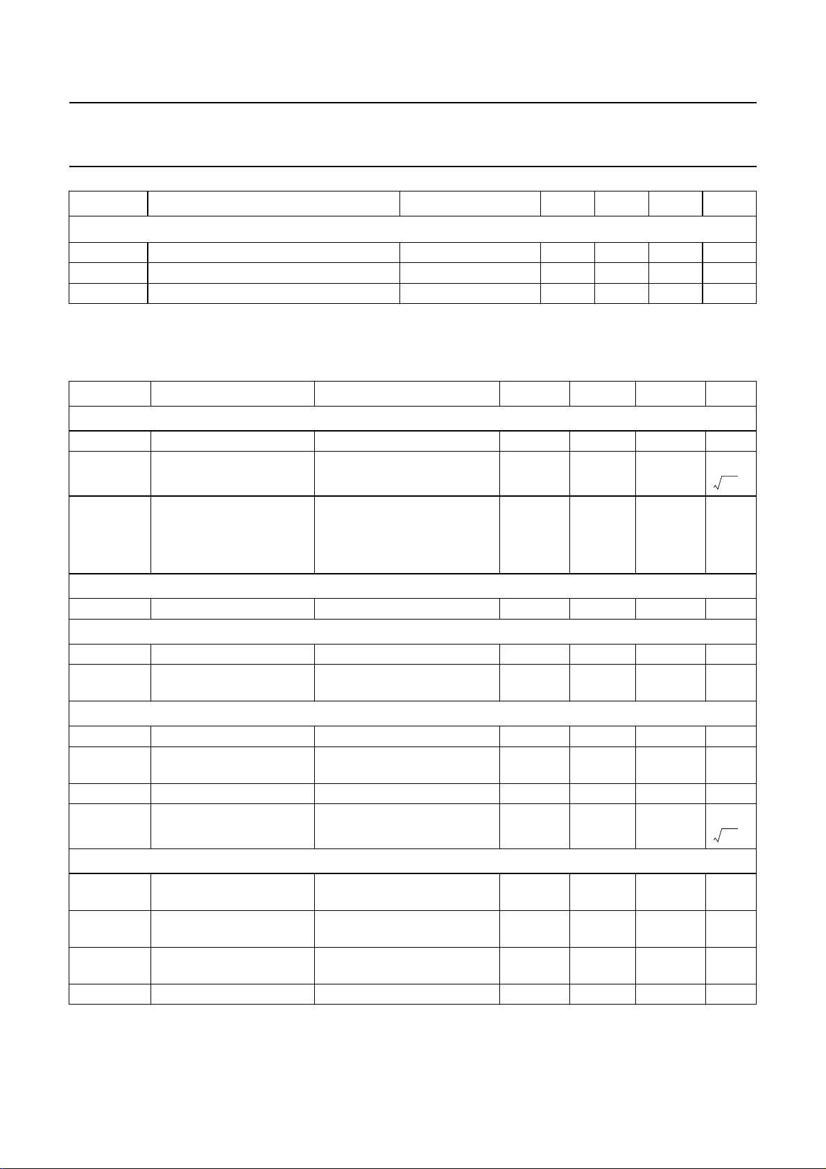
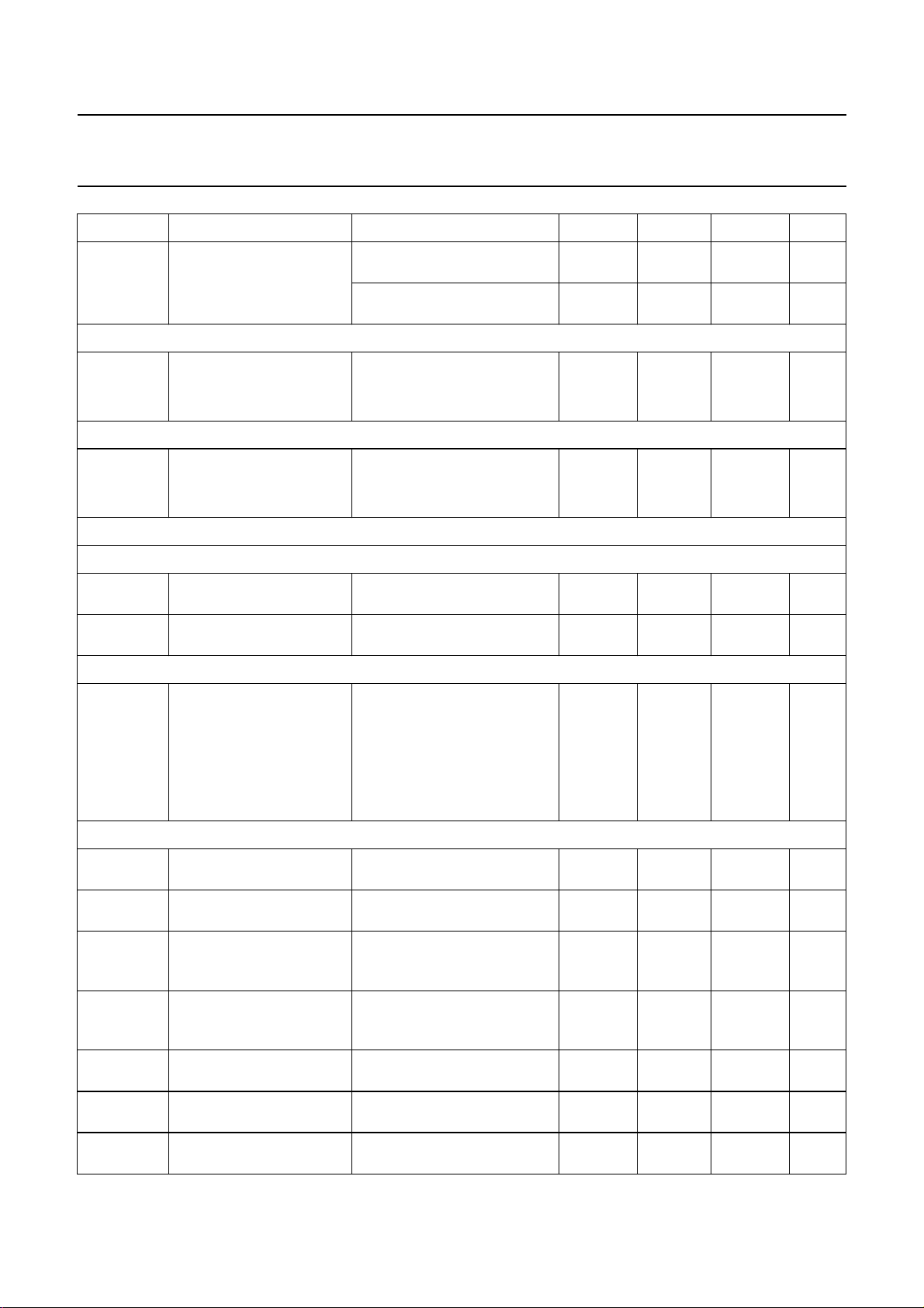
4 QUICK REFERENCE DATA
SYMBOL PARAMETER CONDITIONS MIN. TYP. MAX. UNIT
V
DDA(n)
I
DDA(tot)
V
DDA2
I
DDA2
V
DDD
I
DDD
f
AM(ant)
f
FM(ant)
f
FM(WB)(ant)
T
amb
AM overall system parameters (1 × SFE10.7MS3; 1 × SFR450H)
(S+N)/N signal plus noise-to-noise ratio m = 0.3 − 58 − dB
THD total harmonic distortion m = 0.8 − 0.3 − %
FM overall system parameters (3 × SFE10.7MS3)
(S+N)/N signal plus noise-to-noise ratio ∆f = 22.5 kHz;
THD total harmonic distortion ∆f=75kHz − 0.6 1 %
analog supply voltage 1, 3, 4, 5
8 8.5 9 V
and 6
total analog supply current 1, 3, 4,
5 and 6
FM mode 45 56 67 mA
AM mode 39 49 59 mA
analog supply voltage 2 4.75 5 5.25 V
analog supply current 2 FM mode 6.5 8.1 9.8 mA
AM mode 4.7 5.9 7.1 mA
digital supply voltage 4.75 5 5.25 V
digital supply current FM mode 18 23 28 mA
AM mode 18 23 28 mA
AM input frequency LW 0.144 − 0.288 MHz
MW 0.522 − 1.710 MHz
SW 5.85 − 9.99 MHz
FM input frequency 65 − 108 MHz
FM weather band input frequency 162.4 − 162.55 MHz
ambient temperature −40 − +85 °C
m = 0.9 − 0.5 − %
− 65 − dB
de-emphasis = 50 µs
2001 Apr 12 4
This text is here in white to force landscape pages to be rotated correctly when browsing through the pdf in the Acrobat reader.This text is here in
_white to force landscape pages to be rotated correctly when browsing through the pdf in the Acrobat reader.This text is here inThis text is here in
white to force landscape pages to be rotated correctly when browsing through the pdf in the Acrobat reader. white to force landscape pages to be ...
2001 Apr 12 5
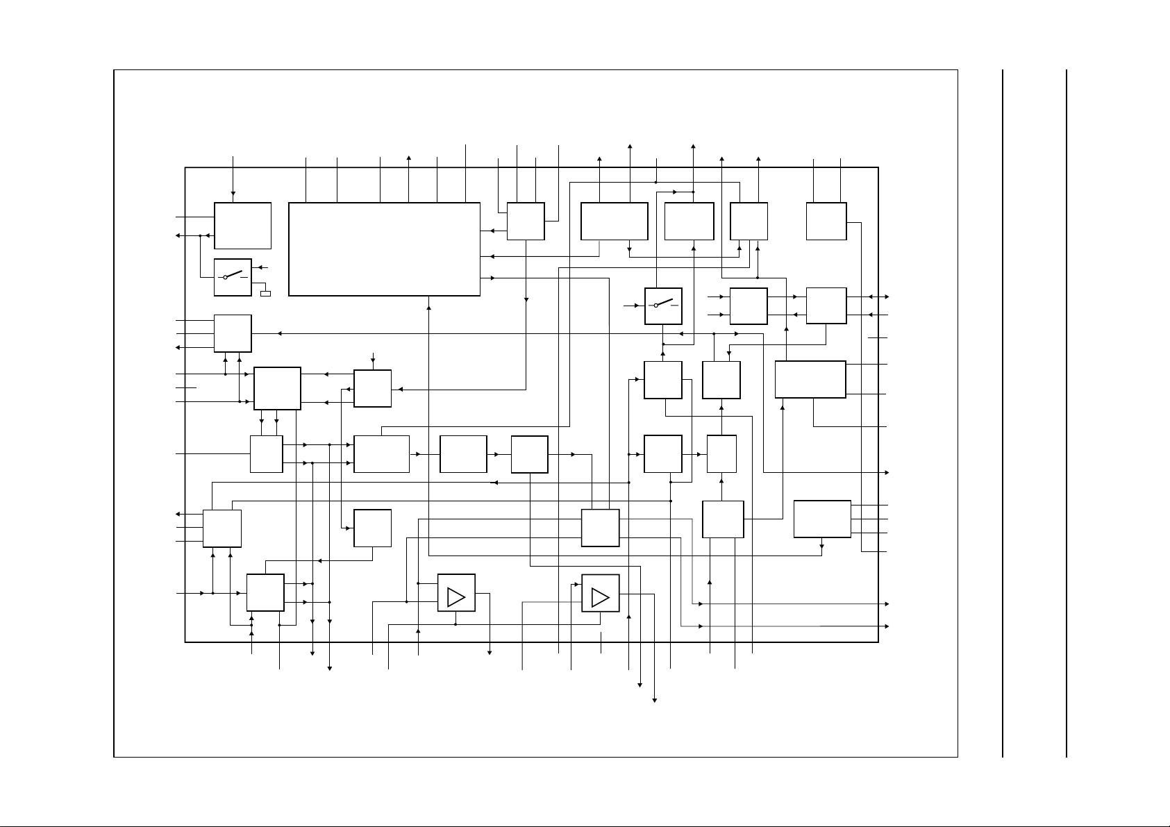
5 BLOCK DIAGRAM
Philips Semiconductors Product specification
New In Car Entertainment (NICE) car radio TEA6845AH; TEA6845H
DAATD
DAAOUT
T1FMAGC
T2FMAGC
IFMAGC
FMMIXIN2
RFGND
FMMIXIN1
V
ref(FMMIX)
IAMAGC
T2AMAGC
T1AMAGC
VCO
BLANK
PULSE
V
42
DDA3
43 49484746 504544
SEQUENTIAL
CIRCUIT FOR
RDS UPDATING
I2C-bus
×
AM
MIXER2
AM
IF AGC
AM
LEVEL
AMAFIF2AFHOLD
AM
DETECTOR
FM IF
AM IF2
LEVEL
DAA
LIMITER/
LEVEL
Σ
FM
FMMPXRDSMPXTRDSMUTEAFSAMPLEOSCTNKVCOGND
MUTE
IF
COUNT
V
DDA2
2 ms/20 ms
DEMODULATOR
CRYSTAL
OSCILLATOR
V
POWER
SUPPLY
I2C-BUS
DDA1
51
52
53
54
55
56
57
58
59
60
61
62
SDA
SCL
IF2GND
QDET1
QDET2
C
AFC
V
level
XTAL1
XTALGND
XTAL2
I
ref
V
DDD
10.25 MHz
DGND
TEA6845AH
TEA6845H
PEAK/
AVERAGE
CPOUTDAAIN
TUNING SYSTEM
V
DDA4
36 3938373534
WX
N1
÷2
90°
AM-NOISE
DETECTOR
N2
÷5/10
ref
V
tune
33
32
ANTENNA
31
30
29
28
27
26
25
24
23
22
21
AGC
AM
RF AGC
FM
DAA
AM
×
FM
I/Q MIXER
90°
f
OSCFDB
40 41
AMMIX1IN1
20
AM
MIXER 1
19 18
AMMIX1IN2
×
17 16
MIX1OUT2 IFAMP1DEC IFAMP1IN IFAMP1OUT IF1GND FMLIMIN
V
DDA5
MIX1OUT1
15 14 13
V
DDA6
IFAMP1
12 11 10 798 6 2345
IFAMP2DEC IFAMP2IN AMIF2IN AMIF2DEC
Fig.1 Block diagram.
C
handbook, full pagewidth
offset
IFAMP2
AMNBHOLD
IFAMP2OUT
C
FMLIMDEC
1
AGC
63
64
MGU350
AMMIX2OUT1
AMMIX2OUT2

Philips Semiconductors Product specification
New In Car Entertainment (NICE) car radio TEA6845AH; TEA6845H
6 PINNING
SYMBOL PIN DESCRIPTION
C
AGC
FMLIMDEC 2 FM limiter decoupling
FMLIMIN 3 FM limiter input (10.7 MHz)
AMIF2DEC 4 decoupling for AM IF2 input
IFAMP2OUT 5 IF amplifier 2 output (10.7 MHz)
AMNBHOLD 6 AM noise blanker hold output
AMIF2IN 7 AM IF2 input (450 kHz) for demodulator AGC and AM level detector
IF1GND 8 AM IF1 ground
IFAMP2IN 9 IF amplifier 2 input (10.7 MHz)
C
offset
IFAMP2DEC 11 IF amplifier 2 decoupling and AGC capacitor for AM noise blanker
IFAMP1OUT 12 IF amplifier 1 output (10.7 MHz)
IFAMP1IN 13 IF amplifier 1 and AM mixer 2 input (10.7 MHz)
V
DDA6
IFAMP1DEC 15 AM mixer 2 and FM IF amplifier 1 decoupling
MIX1OUT1 16 FM mixer and AM mixer 1 IF output high (10.7 MHz)
MIX1OUT2 17 FM mixer and AM mixer 1 IF output low (10.7 MHz)
V
DDA5
AMMIX1IN2 19 AM mixer 1 input 2
AMMIX1IN1 20 AM mixer 1 input 1
T1AMAGC 21 1st time constant output of AM front-end AGC
T2AMAGC 22 2nd time constant of AM front-end AGC
IAMAGC 23 PIN diode drive current output of AM front-end AGC
V
ref(FMMIX)
FMMIXIN1 25 input 1 of FM RF mixer
RFGND 26 RF ground
FMMIXIN2 27 input 2 of FM RF mixer
IFMAGC 28 PIN diode drive current output of FM front-end AGC
T2FMAGC 29 2nd time constant of FM front-end AGC
T1FMAGC 30 1st time constant of FM front-end AGC
DAAOUT 31 output of digital alignment circuit for antenna tank circuit
DAATD 32 temperature compensation diode of digital auto alignment circuit for antenna tank circuit
DAAIN 33 input of digital auto alignment circuit for antenna tank circuit
V
tune
CPOUT 35 charge pump output
V
DDA4
f
ref
V
DDD
DGND 39 digital ground
VCOGND 40 VCO ground
1 AMIFAGC capacitor
10 DC feedback for offset compensation RDS mute
14 analog supply voltage 6 (8.5 V) for IF amplifier 1 and 2
18 analog supply voltage 5 (8.5 V) for FM mixer and AM mixer 1
24 reference voltage for FM mixer
34 tuning voltage
36 analog supply voltage 4 (8.5 V) for tuning PLL
37 reference frequency output for signal processor IC
38 digital supply voltage (5 V)
2001 Apr 12 6

Philips Semiconductors Product specification
New In Car Entertainment (NICE) car radio TEA6845AH; TEA6845H
SYMBOL PIN DESCRIPTION
OSCFDB 41 VCO feedback
OSCTNK 42 VCO tank circuit
V
DDA3
AFSAMPLE 44 AF sample flag output for car audio signal processor IC
AFHOLD 45 AF hold flag output for car audio signal processor IC
TRDSMUTE 46 time constant for RDS update mute
AMAFIF2 47 AM demodulator AF output or IF2 output for AM stereo (multiplexed by I2C-bus)
RDSMPX 48 MPX output for RDS decoder and signal processor (not muted)
FMMPX 49 FM demodulator MPX output
V
DDA2
V
DDA1
SDA 52 I2C-bus data line input and output
SCL 53 I2C-bus clock line input
IF2GND 54 AM IF2 ground
QDET1 55 quadrature demodulator tank 1
QDET2 56 quadrature demodulator tank 2
C
AFC
V
level
XTAL1 59 crystal oscillator 1
XTALGND 60 crystal oscillator ground
XTAL2 61 crystal oscillator 2
I
ref
AMMIX2OUT1 63 AM mixer 2 output 1 (450 kHz)
AMMIX2OUT2 64 AM mixer 2 output 2 (450 kHz)
43 analog supply voltage 3 (8.5 V) for VCO
50 analog supply voltage 2 (5 V) for on-chip power supply
51 analog supply voltage 1 (8.5 V) for on-chip power supply
57 FM demodulator AFC capacitor
58 level voltage output for AM and FM
62 reference current for power supply
2001 Apr 12 7
Philips Semiconductors Product specification
New In Car Entertainment (NICE) car radio TEA6845AH; TEA6845H
handbook, full pagewidth
AFC
XTAL1
59
level
V
58
C
QDET2
QDET1
IF2GND
57
56
55
54
SCL
53
SDA
52
51
50
49
V
DDA1
V
DDA2
FMMPX
C
AGC
FMLIMDEC
FMLIMIN
1
2
3
ref
AMMIX2OUT1
AMMIX2OUT2
64
I
63
62
XTAL2
61
XTALGND
60
AMIF2DEC
IFAMP2OUT
AMNBHOLD
AMIF2IN
IF1GND
IFAMP2IN
C
offset
IFAMP2DEC
IFAMP1OUT
IFAMP1IN
V
DDA6
IFAMP1DEC
MIX1OUT1
MIX1OUT2
V
DDA5
AMMIX1IN2
32
RDSMPX
48
AMAFIF2
47
TRDSMUTE
46
AFHOLD
45
AFSAMPLE
44
V
43
OSCTNK
42
OSCFDB
41
VCOGND
40
DGND
39
V
38
f
37
ref
V
36
CPOUT
35
V
34
DAAIN
33
MHB877
DDA3
DDD
DDA4
tune
4
5
6
7
8
9
23
TEA6845AH
TEA6845H
24
25
26
27
28
29
30
31
10
11
12
13
14
15
16
17
18
19
20
21
22
T1AMAGC
AMMIX1IN1
IAMAGC
T2AMAGC
FMMIXIN1
ref(FMMIX)
V
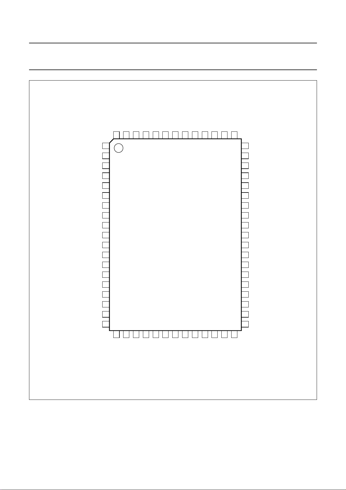
Fig.2 Pin configuration.
2001 Apr 12 8
RFGND
FMMIXIN2
IFMAGC
T2FMAGC
DAAOUT
T1FMAGC
DAATD

Philips Semiconductors Product specification
New In Car Entertainment (NICE) car radio TEA6845AH; TEA6845H
7 FUNCTIONAL DESCRIPTION
7.1 Oscillators
7.1.1 VCO
TheL and CtunedVCO provides the local oscillator signal
for both FM and AM mixer 1. It has a frequency range of
151.2 to 248.2 MHz.
7.1.2 CRYSTAL OSCILLATOR
The crystal oscillator provides a 20.5 MHz signal that is
used for:
• Reference frequency for frequency synthesizer PLL
• Local oscillator for AM mixer 2
• Reference frequency for the IF counter
• Timing signal for the RDS update algorithm
• Reference frequency (75.4 kHz) for the TEA6880H (car
audio signal processor - CASP) or TEF6890H (car radio
integrated signal processor).
7.1.3 PLL
Fast synthesizer PLL tuning system with local control for
inaudible RDS updating.
7.2 FM signal channel
7.2.1 DAA
FM RF Digital Auto Alignment (DAA) circuitry for the
conversion of the VCO tuning voltage to a controlled
alignment voltage for the FM antenna tank circuit.
7.2.2 FM I/Q MIXER
FM quadrature mixer converts FM RF (65 to 162.55 MHz)
to IF of 10.7 MHz. The FM mixer provides inherent image
rejection and high RF sensitivity.
It is capable of tuning the US FM, US weather,
Europe FM, Japan FM and East Europe FM bands:
• US FM = 87.9 to 107.9 MHz
• US weather FM = 162.4 to 162.55 MHz
• Europe FM = 87.5 to 108 MHz
• Japan FM = 76.0 to 91 MHz
• East Europe FM = 65.8 to 74 MHz.
It includes an AGC PIN diode drive circuit for the FM RF
AGC.The PIN diode drive can be activated via theI2C-bus
as a local or distance function.
The AGC threshold is programmable and the keyed AGC
function is switchable via the I2C-bus.
7.2.4 FM IF AMPLIFIERS
The two FM IF amplifiers provide 10 dB and 4 dB
amplification with high linearity and dynamic range.
7.2.5 FM DEMODULATOR
The FM quadrature demodulator includes automatic
centre frequency adjustment and THD compensation.
7.3 AM signal channel
7.3.1 AM TUNER INCLUDING MIXER 1 AND MIXER 2
The AM tuner is realized in a double conversion technique
and is capable of selecting LW, MW and SW bands.
AM mixer 1 converts AM RF to IF1 of 10.7 MHz, while
AM mixer 2 converts IF1 of 10.7 MHz to IF2 of 450 kHz:
• LW = 144 to 288 kHz
• MW = 530 to 1710 kHz (US AM band)
• SW = 5.85 to 9.99 MHz (including the 31 m, 41 m and
49 m bands).
7.3.2 AM RF AGC AND IF2 AGC
The AM RF includes a PIN diode drive circuit. The
threshold detection points for AM AGC are performed at
AM mixer 1 and AM IF2. AGC thresholds are
programmable via the I2C-bus.
7.3.3 AM DETECTOR
The AM detector provides AM level information and
AM AF or AM IF2.
7.3.4 AM AF OR IF2 SWITCH
The AM output provides either a detected AM AF or the
corresponding AM IF2 signal. The IF2 signal can be used
for AM stereo decoder processing.
7.2.3 FM KEYED AGC
FM contains keyed wide-band RF AGC. AGC detection
occursattheFM mixer. The wide-bandRF signalswitches
a narrow band signal (IF) from the FM IF level detector
circuitry that controls the FM RF AGC block.
2001 Apr 12 9
Philips Semiconductors Product specification
New In Car Entertainment (NICE) car radio TEA6845AH; TEA6845H
7.3.5 AM NOISE DETECTOR AND BLANKER
The detection point for the AM noise blanker is the output
stage of AM mixer 1, while blanking is realized at the
output of the mixer 2.
Triggersensitivitycanbemodifiedbychanging the resistor
value at pin AMNBHOLD.
If the test mode is enabled by pin f
• The settling time of the AM IF2 AGC is reduced to less
than 100 ms in the nominal application
• The digital-to-analog converters for the antenna DAA
and the level DAA can be clocked directly by the SCL
line of the I2C-bus
• The output at pin f
7.3.6 FM AND AM LEVEL DETECTOR
FM and AM level detectors provide the temperature
compensated output voltage. The starting points and
slopes of the level detector outputs are programmable via
the I2C-bus.
TEA6880H or TEF6890H reference frequency, PLL
reference frequency or PLL programmable divider
output frequency
• The RDS update control circuit can be clocked directly
via pin DAATD
• Pin T1AMAGC can be used to enable the load PLL
7.4 Test mode
The test mode of the IC is activated by:
circuit of the RDS update control circuit
• Charge pumps can be set into 3-state mode.
• Sending the test byte (byte 5) to the IC
• Connecting pin f
• Applying 50 µA to pin f
through a 100 kΩ resistor to V
ref
ref.
DDA1
8 LIMITING VALUES
In accordance with the Absolute Maximum Rating System (IEC 60134).
:
ref
can be selected by the I2C-bus:
ref
SYMBOL PARAMETER CONDITIONS MIN. MAX. UNIT
V
DDA1
V
DDA2
V
DDA3
V
DDA4
V
DDA5
V
DDA6
V
DDD
∆V
DD8.5-DD5
analog supply voltage 1 for on-chip power supply −0.3 +10 V
analog supply voltage 2 for on-chip power supply −0.3 +6.5 V
analog supply voltage 3 for VCO −0.3 +10 V
analog supply voltage 4 for tuning PLL −0.3 +10 V
analog supply voltage 5 for FM and AM RF −0.3 +10 V
analog supply voltage 6 for IF amplifier 1 and 2 −0.3 +10 V
digital supply voltage −0.3 +6.5 V
difference between any 8.5 V supply voltage and any
note 1 −0.3 − V
5 V supply voltage
T
stg
T
amb
V
es
storage temperature −55 +150 °C
ambient temperature −40 +85 °C
electrostatic handling voltage note 2 −200 +200 V
note 3 −2000 +2000 V
Notes
1. To avoid damages and wrong operation it is necessary to keep all 8.5 V supply voltages at a higher level than any
5 V supply voltage. This is also necessary during power-on and power-down sequences. Precautions have to be
provided in such a way that interferences can not pull down the 8.5 V supply below the 5 V supply.
2. Machine model (R = 0 Ω, C = 200 pF).
3. Human body model (R = 1.5 kΩ, C = 100 pF).
2001 Apr 12 10

Philips Semiconductors Product specification
New In Car Entertainment (NICE) car radio TEA6845AH; TEA6845H
9 THERMAL CHARACTERISTICS
SYMBOL PARAMETER CONDITIONS VALUE UNIT
R
th(j-a)
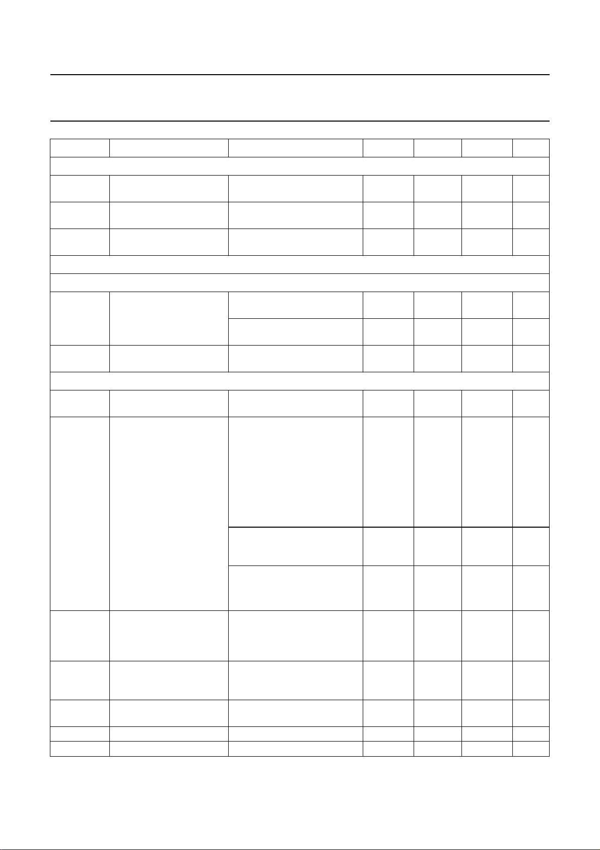
10 DC CHARACTERISTICS
V
DDA1=VDDA3=VDDA4=VDDA5=VDDA6
SYMBOL PARAMETER CONDITIONS MIN. TYP. MAX. UNIT
Supply voltage
V
DDA(n)
V
DDA2
V
DDD
Supply current in FM mode
I
DDD
I
DDA1
I
DDA2
I
DDA3
I
DDA4
I
DDA5
I
DDA6
I
MIX1OUT1
I
MIX1OUT2
Supply current in AM mode
I
DDD
I
DDA1
I
DDA2
I
DDA3
I
DDA4
I
DDA5
I
MIX1OUT1
I
MIX1OUT2
I
AMMIX2OUT1
I
AMMIX2OUT2
thermal resistance from junction to ambient in free air
TEA6845AH 46 K/W
TEA6845H 48 K/W
= 8.5 V; V
DDA2
=5V; V
DDD
=5V; T
=25°C; unless otherwise specified.
amb
analog supply voltage 1, 3, 4, 5 and 6 8 8.5 9 V
analog supply voltage 2 4.75 5 5.25 V
digital supply voltage 4.75 5 5.25 V
digital supply current 18 23 28 mA
analog supply current 1 for on-chip power
− 15 − mA
supply
analog supply current 2 for on-chip power
6.5 8.1 9.8 mA
supply
analog supply current 3 for VCO − 6.5 − mA
analog supply current 4 for tuning PLL test mode;
− 2.9 − mA
bit TMS3 = 1
analog supply current 5 for FM RF − 5 − mA
analog supply current 6 for FM IF
10 12 14 mA
amplifier 1 and 2
bias current of FM mixer output 1 4.8 6 7.2 mA
bias current of FM mixer output 2 4.8 6 7.2 mA
digital supply current 18 23 28 mA
analog supply current 1 for on-chip power
− 17.5 − mA
supply
analog supply current 2 for on-chip power
4.7 5.9 7.1 mA
supply
analog supply current 3 for VCO − 6.5 − mA
analog supply current 4 for tuning PLL test mode;
− 1.6 − mA
bit TMS3 = 1
analog supply current 5 for RF − 1.8 − mA
bias current of AM mixer 1 output 1 4.8 6 7.2 mA
bias current of AM mixer 1 output 2 4.8 6 7.2 mA
bias current of AM mixer 2 output 1 3.6 4.5 5.4 mA
bias current of AM mixer 2 output 2 3.6 4.5 5.4 mA
2001 Apr 12 11
Philips Semiconductors Product specification
New In Car Entertainment (NICE) car radio TEA6845AH; TEA6845H
SYMBOL PARAMETER CONDITIONS MIN. TYP. MAX. UNIT
On-chip power supply reference current generator: pin I
V
o(ref)
R
o
I
o(max)
output reference voltage 4 4.25 4.5 V
output resistance 8 11 13 kΩ
maximum output current −100 − +100 nA
ref
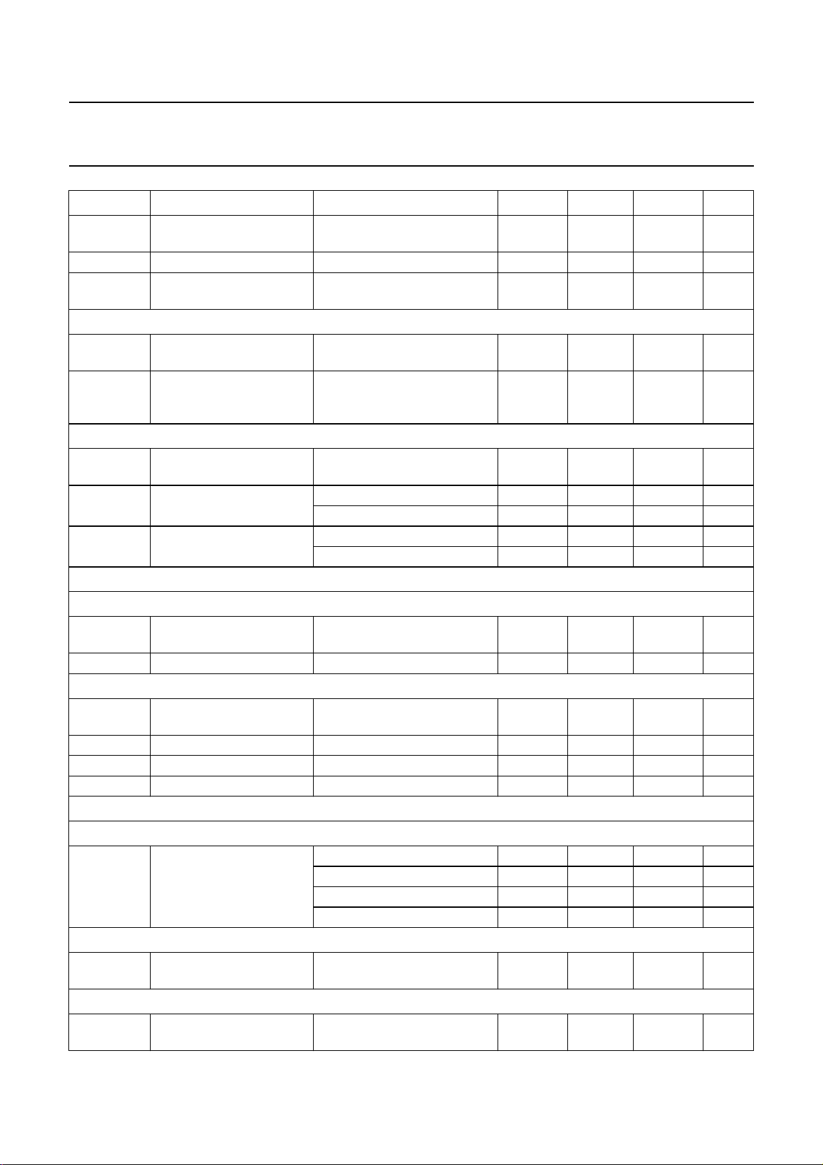
11 AC CHARACTERISTICS
V
DDA1=VDDA3=VDDA4=VDDA5=VDDA6
= 8.5 V; V
DDA2
=5V; V
DDD
=5V; T
=25°C; see Figs 9 and 10; unless
amb
otherwise specified.
SYMBOL PARAMETER CONDITIONS MIN. TYP. MAX. UNIT
Voltage controlled oscillator
f
osc
C/N carrier-to-noise ratio f
RR ripple rejection f
oscillator frequency 151.2 − 248.2 MHz
= 200 MHz; ∆f = 10 kHz − 101 −
osc
= 100 Hz;
ripple
V
DDA3(ripple)
f
osc
f
osc
= 100 mV (RMS)
= 250 MHz − 97 − dB
= 200 MHz − 99 − dB
FEEDBACK INPUT: PIN OSCFDB
V
i(bias)
input bias voltage 2.2 2.8 3.4 V
TANK CIRCUIT OUTPUT: PIN OSCTNK
V
O
V
o(rms)
DC output voltage 5 6.1 7.2 V
AC output voltage
f
= 200 MHz − 1.5 − V
osc
(RMS value)
Crystal oscillator
f
R
xtal
xtal
crystal frequency 20.4996 20.5 20.5004 MHz
crystal motional
start of operating −−500 Ω
resistance
C
xtal
C/N carrier-to-noise ratio f
crystal shunt capacitance −−18 pF
= 20.5 MHz (10.25 MHz);
xtal
− 112 −
∆f=10kHz
dBc
----------- Hz
dBc
----------- Hz
IRCUIT INPUTS: PINS XTAL1, XTAL2 AND XTALGND
C
V
xtal(rms)
crystal voltage
note 2 − 350 − mV
(RMS value)
V
XTAL1
V
XTAL2
R
C
,
i
i
DC bias voltage 1.7 2.1 2.5 V
real part of input
impedance
V
XTAL1
note 1
− V
XTAL2
input capacitance note 1 8 10 12 pF
2001 Apr 12 12
= 1 mV;
−500 −− Ω
Philips Semiconductors Product specification
New In Car Entertainment (NICE) car radio TEA6845AH; TEA6845H
SYMBOL PARAMETER CONDITIONS MIN. TYP. MAX. UNIT
I
XTALGND
Oscillator divider N1
N1 oscillator divider ratio FM mode:
Oscillator divider N2
N2 oscillator divider ratio AM mode
Synthesizer
crystal oscillator circuit
current
start-up at
V
XTAL1=VXTAL2
operating at
V
− V
XTAL1
XTAL2
= 2.1 V
= ±400 mV
− 9 − mA
− 1.5 − mA
standard, Europe and local − 2 −
weather band (WX) − 1 −
SW − 10 −
LW and MW − 5 −
PROGRAMMABLE DIVIDER
N
prog
programmable divider
ratio
∆N
step
programmabledivider step
size
REFERENCE FREQUENCY DIVIDER
N
ref
crystal oscillator divider
ratio
CHARGE PUMP: PIN CPOUT
I
sink(cp1)l
low charge pump 1 peak
sink current
I
source(cp1)l
low charge pump 1 peak
source current
I
sink(cp1)h
high charge pump 1 peak
sink current
I
source(cp1)h
high charge pump 1 peak
source current
I
sink(cp2)
charge pump 2 peak sink
current
I
source(cp2)
charge pump 2 peak
source current
I
Z(cp1)
, I
charge pump 1 or 2
Z(cp2)
current in 3-state
512 − 32767
− 1 −
f
= 20.5 MHz
xtal
f
= 100 kHz − 205 −
ref
f
= 50 kHz − 410 −
ref
f
= 25 kHz − 820 −
ref
f
= 20 kHz − 1025 −
ref
f
= 10 kHz − 2050 −
ref
FM weather band mode;
0.4V<V
CPOUT
< 7.6 V
FM weather band mode;
0.4V<V
CPOUT
< 7.6 V
AM stereo mode; N2 = 10
200 300 400 µA
−400 −300 −200 µA
0.7 1 1.3 mA
(LWand MW);
0.4V<V
AM stereo mode; N2 = 10
CPOUT
< 7.6 V
−1.3 −1 −0.7 mA
(LWand MW);
0.4V<V
FM standard mode;
0.3V<V
FM standard mode;
0.3V<V
0<V
CPOUT
< 7.6 V
CPOUT
100 130 160 µA
< 7.1 V
CPOUT
−160 −130 −100 µA
< 7.1 V
CPOUT
< 8.5 V −5 − +5 nA
2001 Apr 12 13
Philips Semiconductors Product specification
New In Car Entertainment (NICE) car radio TEA6845AH; TEA6845H
SYMBOL PARAMETER CONDITIONS MIN. TYP. MAX. UNIT
CHARGE PUMP: PIN V
I
sink(cp3)
tune
charge pump 3 peak sink
current
I
source(cp3)
charge pump 3 peak
source current
I
Z(cp3)
charge pump 3 current in
3-state
Antenna Digital Auto Alignment (DAA)
DAA INPUT: PIN DAAIN
I
bias(cp)
charge pump buffer input
bias current
V
i(cp)
charge pump buffer input
voltage
DAA OUTPUT: PIN DAAOUT; note 2
V
o(AM)
DAA output voltage in
AM mode
V
o(FM)
DAA output voltage in
FM mode
V
∆V
o(n)
o (T)
DAA output noise voltage FM mode; V
DAA output voltage
variation with temperature
∆V
o (step)
I
o(sink)
I
o(source)
DAA step accuracy FM mode; V
DAA output sink current 0.2V<V
DAA output source current −−−50 µA
FM standard mode;
0.4V<V
tune
< 7.6 V
FM standard mode;
0.4V<V
0<V
tune
< 7.6 V
tune
< 8.5 V −5 − +5 nA
FM mode;
0.4V<V
DAAIN
< 8.0 V
AM mode;
0V<V
DAAIN
< 8.5 V
2.1 3 3.9 mA
−3.9 −3 −2.1 mA
−10 − +10 nA
−10 − +10 nA
0 − 8.5 V
−−0.3 V
V
= 4.0 V;
DAAIN
V
DAATD
= 0.7 V
minimum value −−0.5 V
bits DAA[6:0] set to logic 0 1.5 1.65 1.8 V
value: data
3.8 4 4.2 V
byte 3 = 10101011
maximum value;
8 − 8.5 V
bits DAA[6:0] set to logic 1
V
DAAIN
V
DAATD
= 3.0 V;
= 0.7 V; bits DAA[6:0]
6.2 6.5 6.8 V
set to logic 1
V
=2V
DAAIN
data byte 3 = 11010101 3 3.3 3.6 V
data byte 3 = 10101010 1.8 2 2.2 V
DAAIN
=4V;
− 30 100 µV
data byte 3: bit 6 = 1,
bits 5 to 0 = 0;
B = 300 Hz to 15 kHz
T
= −40 to +85 °C;
amb
−8 − +8 mV
data byte 3 = 10101011;
V
DAATD
= 0.7 V
DAAOUT
< 8.0 V;
0.5V
LSB
V
LSB
1.5V
LSB
n = 0 to 127
DAAOUT
< 8.25 V 50 −− µA
mV
2001 Apr 12 14
Philips Semiconductors Product specification
New In Car Entertainment (NICE) car radio TEA6845AH; TEA6845H
SYMBOL PARAMETER CONDITIONS MIN. TYP. MAX. UNIT
t
st
RR ripple rejection f
C
L
DAA TEMPERATURE COMPENSATION: PIN DAA TD
I
source
TC
source
IF counter (FM IF or AM IF2 counter)
N
IF
T
count(IF)
R
precount
Reference frequency for car sound processor IC; note 3
DAA output settling time 0.2V<V
DAAOUT
< 8.25 V;
−−30 µs
CL= 270 pF
DAA output load
ripple
V
DAAOUT
= 100 Hz; V
< 8.0 V; FM mode −−270 pF
=1mV − 50 − dB
DDA4
capacitance
compensation diode
0.2V<V
< 1.5 V −50 −40 −30 µA
DAATD
source current
temperature coefficient of
compensation diode
0.2V<V
T
= −40 to +85 °C
amb
DAATD
< 1.5 V;
−3 × 10
−10
− +3 × 10
−10K−1
source current
IF counter length for
− 8 − bit
AM and FM
IF counter period data byte 4: bit 7 = 1 − 2 − ms
data byte 4: bit 7 = 0 − 20 − ms
FM IF counter prescaler
ratio
data byte 4: bit 3 = 1 − 10 −
data byte 4: bit 3 = 0 − 100 −
REFERENCE FREQUENCY DIVIDER
N
ref
crystal oscillator divider
ratio
f
ref
VOLTAGE GENERATOR; PIN f
V
o(p-p)
reference frequency f
ref
AC output voltage
= 20.5 MHz − 75.368 − kHz
xtal
(peak-to-peak value)
V
R
R
O
o
L(min)
DC output voltage 3.2 3.4 3.9 V
output resistance −−50 kΩ
minimum load resistance 1 −− MΩ
AM signal channel
AM RF AGC STAGE INPUTS: PINS AMMIX1IN1 AND AMMIX1IN2
V
i(p)
RF input voltage for AGC
start level (peak value)
data byte 5: bit 5 = 0, bit 6 = 0 − 150 − mV
data byte 5: bit 5 = 1, bit 6 = 0 − 275 − mV
data byte 5: bit 5 = 0, bit 6 = 1 − 400 − mV
data byte 5: bit 5 = 1, bit 6 = 1 − 525 − mV
AM IF AGC STAGE INPUTS: PINS AMIF2IN AND AMIF2DEC
V
i(p)
IF2 input voltage (peak
AGC start level 0.20 0.27 0.35 V
value)
AM RF AGC CURRENT GENERATOR OUTPUT: PIN IAMAGC
I
sink(max)
maximum AGC sink
current
V
AMMIX1IN1
(peak value)
> 500 mV
− 272 −
60 100 170 mV
− 15 − mA
2001 Apr 12 15
 Loading...