


DATA SH EET
Preliminary specification
File under Integrated Circuits, IC02
1995 Mar 21
INTEGRATED CIRCUITS
Philips Semiconductors
TDA9614H
Audio processor for VHS hi-fi
and linear audio

1995 Mar 21 2
Philips Semiconductors Preliminary specification
Audio processor for VHS hi-fi
and linear audio
TDA9614H
CONTENTS
1 FEATURES
2 GENERAL DESCRIPTION
3 ORDERING INFORMATION
4 BLOCK DIAGRAM
5 PINNING
6 FUNCTIONAL DESCRIPTION
6.1 Audio I/O switching
6.1.1 Input Select (InputSel)
6.1.2 Normal Select (NormSel)
6.1.3 Volume L/R; AGC
6.1.4 Audio FM Output Mute (AFOMute); Normal
Output Mute (NOMute)
6.1.5 Output Select (OutSel)
6.1.6 RF Converter Mute (RFCMute)
6.1.7 Line Select (LineSel)
6.1.8 Decoder Select (DecodeSel)
6.1.9 Headphone Select (HPSel)
6.1.10 Headphone volume
6.1.11 DC Select (DCSel)
6.2 Linear audio circuits
6.2.1 Record/loop-through
6.2.2 Playback
6.3 Audio FM circuits
6.3.1 Record/loop-through
6.3.2 Playback
6.3.3 Automatic calibration
6.3.4 PAL/NTSC mode
6.4 I2C-bus
6.5 Power-On Reset (POR); derived from digital
supply voltage V
DDD
6.6 Control byte
6.7 Main select byte
6.8 Secondary select byte
6.9 Left/Right (L/R) volume byte
6.10 Headphone volume byte
6.11 Install byte
6.12 Test byte
6.13 Read byte
7 LIMITING VALUES
8 THERMAL CHARACTERISTICS
9 DC CHARACTERISTICS
10 AC CHARACTERISTICS
10.1 Record audio FM mode
10.2 Record linear audio mode
10.3 Playback Audio FM mode
10.4 Playback linear audio
11 INTERNAL CIRCUITRY
12 TEST AND APPLICATION INFORMATION
12.1 RAF I/O (pin 12)
12.2 RCCOL, RCCOR, RBPF and RFIX
(pins 59, 53, 55 and 49)
13 PACKAGE OUTLINE
14 SOLDERING
14.1 Plastic quad flat packages
14.1.1 By wave
14.1.2 By solder paste reflow
14.1.3 Repairing soldered joints (by hand-held
soldering iron or pulse-heated solder tool)
15 DEFINITIONS
16 LIFE SUPPORT APPLICATIONS
17 PURCHASE OF PHILIPS I2C COMPONENTS

1995 Mar 21 3
Philips Semiconductors Preliminary specification
Audio processor for VHS hi-fi
and linear audio
TDA9614H
1 FEATURES
• All functions controlled by I2C-bus
• No adjustments needed by use of auto-calibration circuit
• Integrated Bandpass Filters (BPFs)
• Low-noise Phase-Locked Loop (PLL) FM (de)modulator
• Low-distortion sample-and-hold switching noise
suppressor
• Integrated HF Low-Pass Filter (LPF) and summator
• Integrated audio LPF
• 5 stereo inputs (left and right channel):
– TUNL and TUNR
– CINL and CINR
– EXT1L and EXT1R
– EXT2L and EXT2R
– EXT3L and EXT3R
• Additional mono input: Second Audio Program (SAP)
• Independent Input/Output (I/O) selections and 2nd line
output
• Linear audio
• DC output for VU meter drive
• Direct headphone drive
• RF converter output with overload Automatic Gain
Control (AGC)
• Integrated standby mode for low current consumption
• E-E performance (record + playback):
– Total Harmonic Distortion (THD): 0.05%
(−8 dBV, 1 kHz)
– linearity error: 0.1 dB (−88 dBV, 1 kHz)
– noise: −93 dBV (20 Hz to 20 kHz).
2 GENERAL DESCRIPTION
The TDA9614H is an audio processing IC for VHS hi-fi and
linear audio, digitally controlled via the I2C-bus. The
FM (de)modulator and peak noise reduction functions are
highly integrated, resulting in few external components
and no external adjustments.
In addition special functions for audio mixing, dubbing and
descrambling have been implemented.
3 ORDERING INFORMATION
Note
1. When using IR reflow soldering it is recommended that the Drypack instructions in the
“Quality Reference Handbook”
(order number 9398 510 63011) are followed.
TYPE NUMBER
PACKAGE
NAME DESCRIPTION VERSION
TDA9614H QFP64
(1)
plastic quad flat package; 64 leads (lead length 1.95 mm);
body 14 × 20 × 2.8 mm
SOT319-2
1995 Mar 21 4
Philips Semiconductors Preliminary specification
Audio processor for VHS hi-fi
and linear audio
TDA9614H
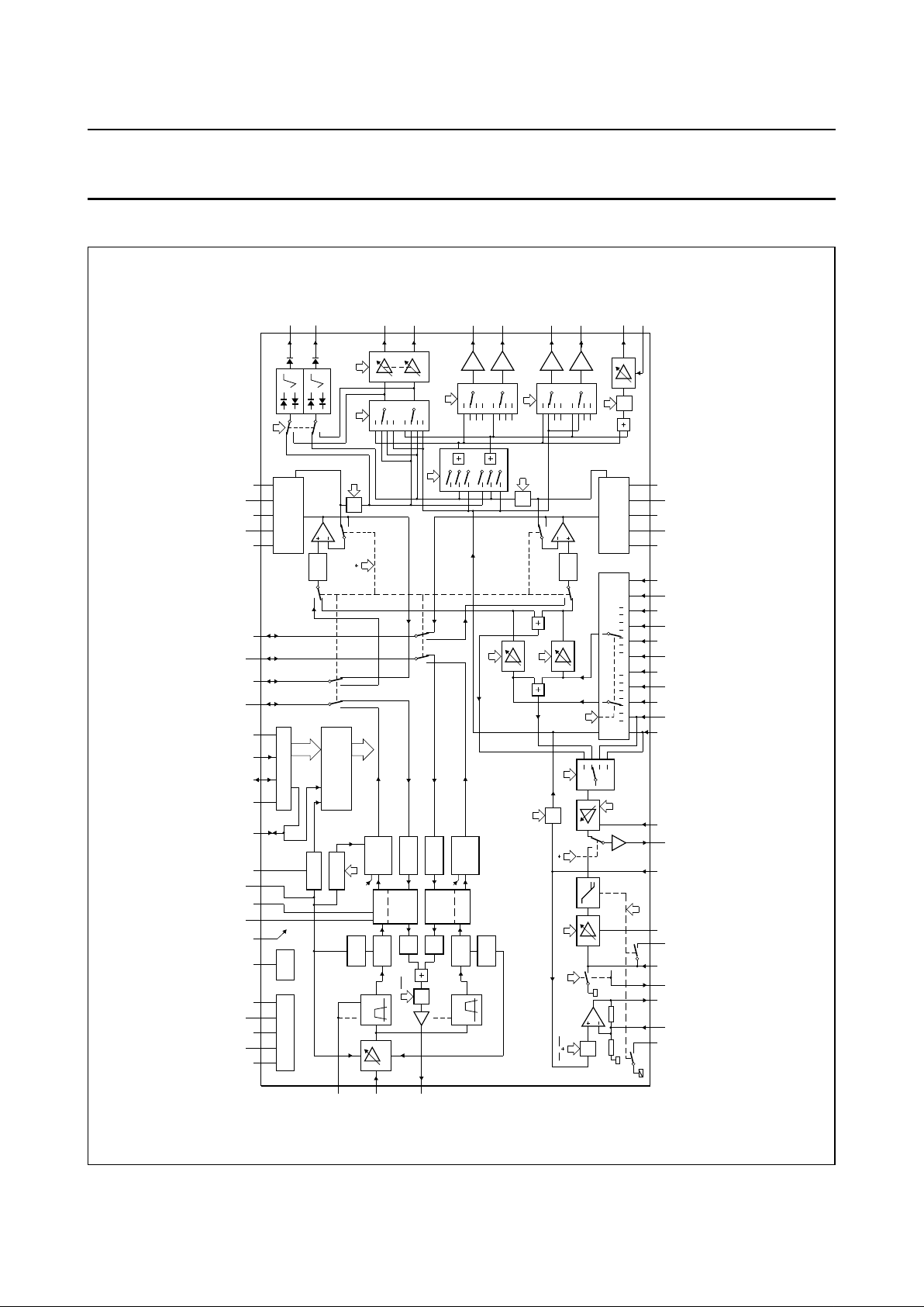
4 BLOCK DIAGRAM
MBE275
SUPPLY AND V
ref
I
ref
HF AGC
BPF
BPF
M
RAF
HF
LPF
HF
LIMITER
HF
LPF
LEVEL
DETECT
HF
LIMITER
LEVEL
DETECT
PLL
1.3 MHz
1.4 MHz
CCO
PLL
1.7 MHz
1.8 MHz
CCO
AUDIO
CLIPPER
SAMPLE-
AND-
HOLD
SAMPLE-
AND-
HOLD
AUDIO
CLIPPER
M
RN IPN RN
PBSet
PB eq
LP
RN IPN
AGCN
Normal Sel
Input Sel
NOISE REDUCTION
volume R
AUDIO
LPF
M
AFOMute
volume L
M
NOMute
Out Sel
M
RFCMute
volume HP
Line Sel
Dec Sel
HP Sel
2
6107113
8109
11
M
AFOMute
NOISE REDUCTION
AUDIO
LPF
DC Sel
RAF IPAF
DOC
DOC
MUTE
I C
2
50 43 58 54 42 49 61 53 59 60 62 12 13 14 15 16 63 64 52 51 37 38 39 40 41
23
24
25
26
19
20
21
22
18
17
48 47 46 45 447 8 9 10 112 3 4 5 61
28 29 2736353432333130
56
57
55
RBPF
FMIN
FMOUT
EQSW RECOUT PBIN
RECEQ LINREC RESSW
PBDC LININ
LINOUT
LINAGC SAP TUNR CINR EXT1R EXT2R EXT3R
TUNL CINL EXT1L EXT2L EXT3L
DCFBR EMPHR
DCREFR
DETR
RECTR
RFCAGC
RFCOUT
LINER
LINEL
LINE2R
LINE2L
HPOUTR
HPOUTL
DCOUTR
DCOUTL
DETL
RECTL
EMPHL
DCREFL
DCFBLAFNR
AFMR
AFNL
AFML
V
SSD
V
DDD SCLSDARAFCMUTE
ENVOUT
RCCOL
RCCOR
HIDRFIX
V
V
DDA1
V
SSA1
V
DDA2
V
SSA2
TDA9614H
ref
Fig.1 Block diagram.
1995 Mar 21 5
Philips Semiconductors Preliminary specification
Audio processor for VHS hi-fi
and linear audio
TDA9614H
5 PINNING
SYMBOL PIN DESCRIPTION
SAP 1 Second Audio Program (SAP) input.
TUNL 2 Left channel tuner input.
TUNR 3 Right channel tuner input.
CINL 4 Left channel cinch input.
CINR 5 Right channel cinch input.
EXT1L 6 Left channel external 1 input.
EXT1R 7 Right channel external 1 input.
EXT2L 8 Left channel external 2 input.
EXT2R 9 Right channel external 2 input.
EXT3L 10 Left channel external 3 input.
EXT3R 11 Right channel external 3 input.
RAF 12 Record/playback switch drive output for head amplifier control or input for overruling
the I2C-bit RAF.
V
DDD
13 Digital supply voltage for I2C-bus (+5 V).
SDA 14 Data input/output for I2C-bus.
SCL 15 Clock input for I2C-bus.
V
SSD
16 Digital ground for I2C-bus.
RFCAGC 17 RF converter AGC-time constant.
RFCOUT 18 RF converter drive output.
LINE2L 19 Line 2 left output (e.g. decoder output).
LINE2R 20 Line 2 right output (e.g. decoder output).
LINEL 21 Line output left.
LINER 22 Line output right.
DCOUTL 23 VU meter drive output left.
DCOUTR 24 VU meter drive output right.
HPOUTL 25 Headphone drive output left.
HPOUTR 26 Headphone drive output right.
LINAGC 27 Linear audio AGC-time constant.
LININ 28 Audio input for linear audio to REC equalizer and output select.
LINOUT 29 Audio output from AGC or PB equalizer.
EQSW 30 Long Play (LP) equalization switch; 15 Ω on resistance and 150 kΩ input impedance.
RECEQ 31 Linear audio recording amplifier negative feedback input for connecting a record
equalization network.
LINREC 32 Digital output controlled by I2C-bit RN; can be used to drive an external (high voltage)
head switch and possibly the bias oscillator.
RECOUT 33 Linear audio recording amplifier output.
PBIN 34 Linear audio playback amplifier input; during playback the impedance is 100 kΩ;
during record the impedance is 7 Ω.
RESSW 35 Long Play equalization switch 50 Ω on and 150 kΩ off impedance to PBIN.
PBDC 36 Linear audio playback amplifier DC decoupling.
1995 Mar 21 6
Philips Semiconductors Preliminary specification
Audio processor for VHS hi-fi
and linear audio
TDA9614H
DCFBL 37 DC feedback left.
DCREFL 38 DC reference left.
EMPHL 39 Total emphasis left (240 to 20 µs).
RECTL 40 Rectifier DC decoupling left.
DETL 41 Attack/recovery timing left.
V
ref
42 Noise filtering of 3.8 V reference voltage (external capacitor required for filtering).
V
SSA1
43 Analog ground 1 for LF circuits.
DETR 44 Attack/recovery timing right.
RECTR 45 Rectifier DC decoupling right.
EMPHR 46 Total emphasis right (240 to 20 µs).
DCREFR 47 DC reference right.
DCFBR 48 DC feedback right.
RFIX 49 Fixed bias current generation circuit by using an external 180 kΩ resistor to ground.
V
DDA1
50 Analog supply voltage 1 for LF circuits (+12 V).
AFNR 51 Audio output from noise reduction of right channel (record and loop-through) or audio
input for noise reduction of right channel (playback).
AFMR 52 Audio input for audio clipper of right channel (record and loop-through) or audio
output from sample-and-hold (playback).
RCCOR 53 Voltage-to-current transfer for right channel oscillator by means of an external resistor
to ground.
V
SSA2
54 Analog ground 2 for HF circuits.
RBPF 55 Bias current generation for the internal band-pass filters by means of an external
resistor to ground.
FMOUT 56 FM output.
FMIN 57 FM input.
V
DDA2
58 Analog supply voltage 2 for HF circuits (+5 V).
RCCOL 59 Voltage-to-current transfer for left channel oscillator by means of an external resistor
to ground.
ENVOUT 60 Level detector output (external capacitor required for filtering).
HID 61 Head Identification Pulse (HID) input for sample-and-hold circuits.
CMUTE 62 Mute timing (external capacitor required for playback mute).
AFML 63 Audio input for audio clipper of left channel (record and loop-through) or audio output
from sample-and-hold circuit of left channel (playback).
AFNL 64 Audio output from noise reduction of left channel (record and loop-through) or audio
input for noise reduction of left channel (playback).
SYMBOL PIN DESCRIPTION
1995 Mar 21 7
Philips Semiconductors Preliminary specification
Audio processor for VHS hi-fi
and linear audio
TDA9614H
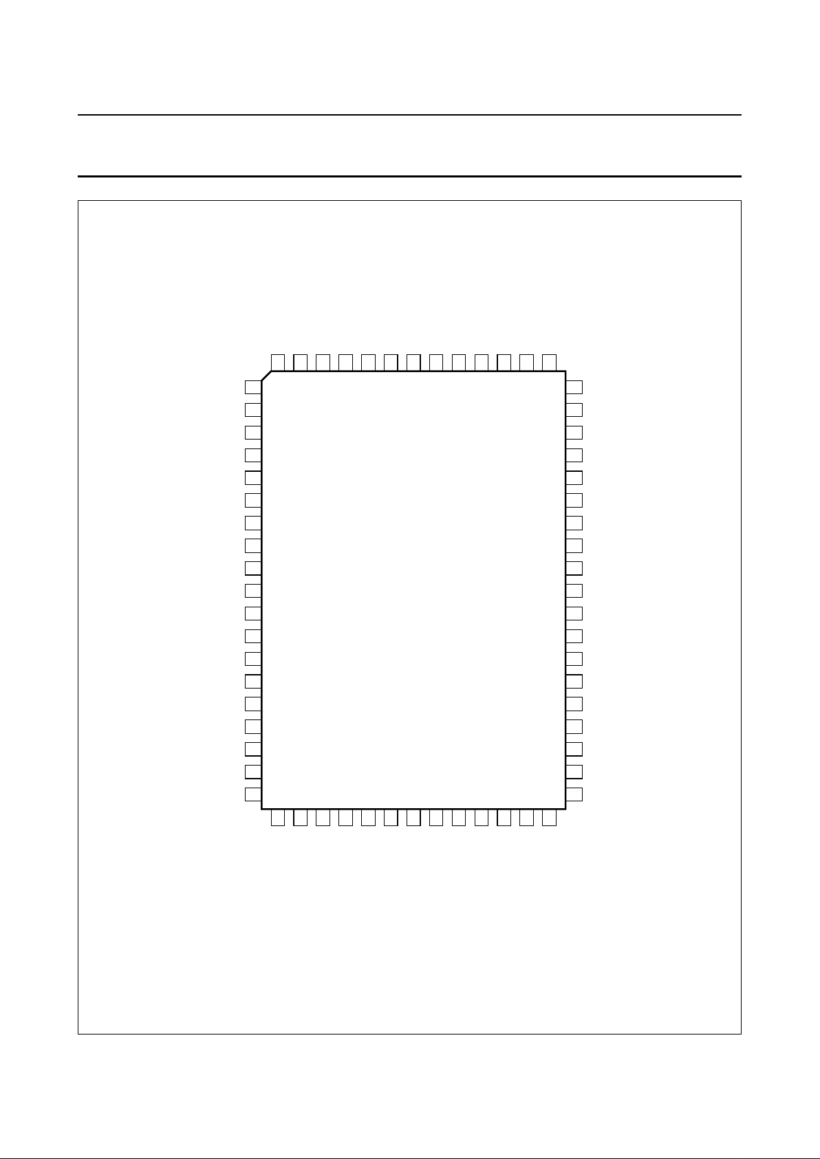
Fig.2 Pin configuration.
handbook, full pagewidth
TDA9614H
MBE278
1
2
3
4
5
6
7
8
9
10
11
12
13
14
15
16
17
18
19
51
50
49
48
47
46
45
44
43
42
41
40
39
38
37
36
35
34
33
20
21
22
23
24
25
26
27
28
29
30
31
32
64
63
62
61
60
59
58
57
56
55
54
53
52
RECOUT
PBIN
RESSW
PBDC
DCFBL
DCREFL
EMPHL
RECTL
DETL
V
DETR
RECTR
EMPHR
DCREFR
DCFBR
RFIX
AFNR
ref
V
SSA1
V
DDA1
SAP
TUNL
TUNR
CINL
CINR
EXT1L
EXT1R
EXT2L
EXT2R
EXT3L
EXT3R
RAF
V
SDA
SCL
RFCAGC
RFCOUT
LINE2L
LINE2R
LINEL
LINER
DCOUTL
DCOUTR
HPOUTL
HPOUTR
LINAGC
LININ
LINOUT
EQSW
RECEQ
LINREC
DDD
V
SSD
AFNL
AFML
CMUTE
HID
ENVOUT
RCCOLVFMIN
FMOUT
RBPF
RCCOR
AFMR
DDA2
V
SSA2

1995 Mar 21 8
Philips Semiconductors Preliminary specification
Audio processor for VHS hi-fi
and linear audio
TDA9614H
6 FUNCTIONAL DESCRIPTION
MBE276
TDA9614H
InputSel
TUNER
CINCH
EXT1
EXT2
EXT3
SAP
NORMAL
EXT3/ST
Volume L/R
14 dBto49 dB
MUTE
AFM MUTE
AFOMute
OutSel
STEREO
LEFT
RIGHT
NORMAL
NOR ST
NOR L
NOR R
MUTE
NORMAL MUTE
NOMute
AGC
ON
OFF
NormalSel
InputSel
InputSel Volume
SAP
TUNER-left
HPSel
OutSel
LEFT
RIGHT
NORMAL
TUNER
CINCH
EXT1
EXT2
EXT3
SAP
LineSel
OutSel
NORMAL
EXT2
EXT3
Volume HP
16 dBto47 dB
MUTE
Decoder Sel
OutSel
TUNER
EXT1
EXT3
MUTE
RFCmute
DCSel
HPSel
STEREO
RFC
LINE
LINE2
decoder
headphone
VU meter
Fig.3 Audio input/output selections.

1995 Mar 21 9
Philips Semiconductors Preliminary specification
Audio processor for VHS hi-fi
and linear audio
TDA9614H
6.1 Audio I/O switching
6.1.1 INPUT SELECT (INPUTSEL)
For the audio FM circuitry eight different audio signals can
be selected. The selection made here for hi-fi is also
available for the linear audio circuitry.
1. TUNER (stereo input; internal tuner of VCR).
2. CINCH (stereo input; connection to hi-fi set).
3. EXT1 (stereo input; TV SCART1).
4. EXT2 (stereo input; decoder, 2nd VCR SCART2).
5. EXT3 (stereo input; front CINCH for e.g. camcorder).
6. SAP (mono input; ‘Second Audio Program’ audio
carrier for NTSC or conventional FM carrier with
NICAM reception).
7. NORMAL (linear audio; [playback] signal of linear
audio).
When inserting a new video signal in an old
audio/video recording the hi-fi audio track is erased.
This setting can keep the current audio available on
the hi-fi track by copying the (playback) linear audio
signal to the hi-fi track during video insert.
8. EXT3/ST (input mix; mono EXT3 on left, mono hi-fi on
right channel).
For linear audio use see Section 6.1.2.
6.1.2 NORMAL SELECT (NORMSEL)
For linear audio four settings can be selected:
1. INPUTSEL (mono signal from input select).
This is the ‘standard’ setting. The signal source
selected with the input select is led to the linear audio
circuit. The linear audio AGC should be switched on.
2. VOLUME (mono signal from [hi-fi] volume control).
The signal source selected with the input select has
now volume control, the linear audio AGC should be
switched off. This setting is for use with ‘audio
dubbing’: inserting a new audio signal on the linear
track in an old audio/video recording. A special audio
dubbing feature is now possible by selecting ‘input mix’
EXT3/ST in the input select. This setting enables us to
use the VCR as a mixer console: an audio source
connected to EXT3 (front CINCH) can be adjusted and
mixed together with the original hi-fi playback signal,
using the left (EXT3) and right (hi-fi playback) volume
controls.
3. SAP (SAP input).
This setting enables simultaneous recording of the
NTSC SAP signal on the linear track and TUNER
stereo on the audio FM track. When receiving a
NICAM audio signal, the linear audio can be used as a
‘backup’ track when received television signals are
weak.
4. TUNER LEFT (left channel [language 1] of TUNER
input).
When receiving dual language transmissions the main
language (language 1) can be recorded on linear
audio. Note that if the SAP input is not used it can be
connected to the right TUNER channel, enabling
language selection for linear audio.
6.1.3 VOLUME L/R; AGC
The volume controls are mainly intended for level
adjusting of the audio signals to be recorded on the hi-fi
track, however using the ‘VOLUME’ setting in the Normal
Select it can also be used to control linear audio. The
volume controls have a control range of +14 dB to −49 dB
in 1 dB steps and a full mute. Because the volume controls
are I2C-bus controlled their actual behaviour is defined by
the VCR’s software. For instance user control can be
‘volume only’, ‘left + right’, ‘volume + balance’ or the
setting can be defined by a ‘digital AGC’ software loop
using the signals at the DC (VU meter) outputs.
The linear audio level can be controlled by an AGC circuit,
which can be switched off when desired. In most cases the
AGC should be used at all settings of the Normal Select
except for ‘VOLUME’.
6.1.4 AUDIO FM OUTPUT MUTE (AFOMUTE);
NORMAL OUTPUT MUTE (NOMUTE)
The audio output signal of the audio FM circuit can be
muted with AFOMute, the linear output signal can be
muted using NOMute. If one of these signals is not used
as an output (or input) signal it is best muted to further
minimize crosstalk.
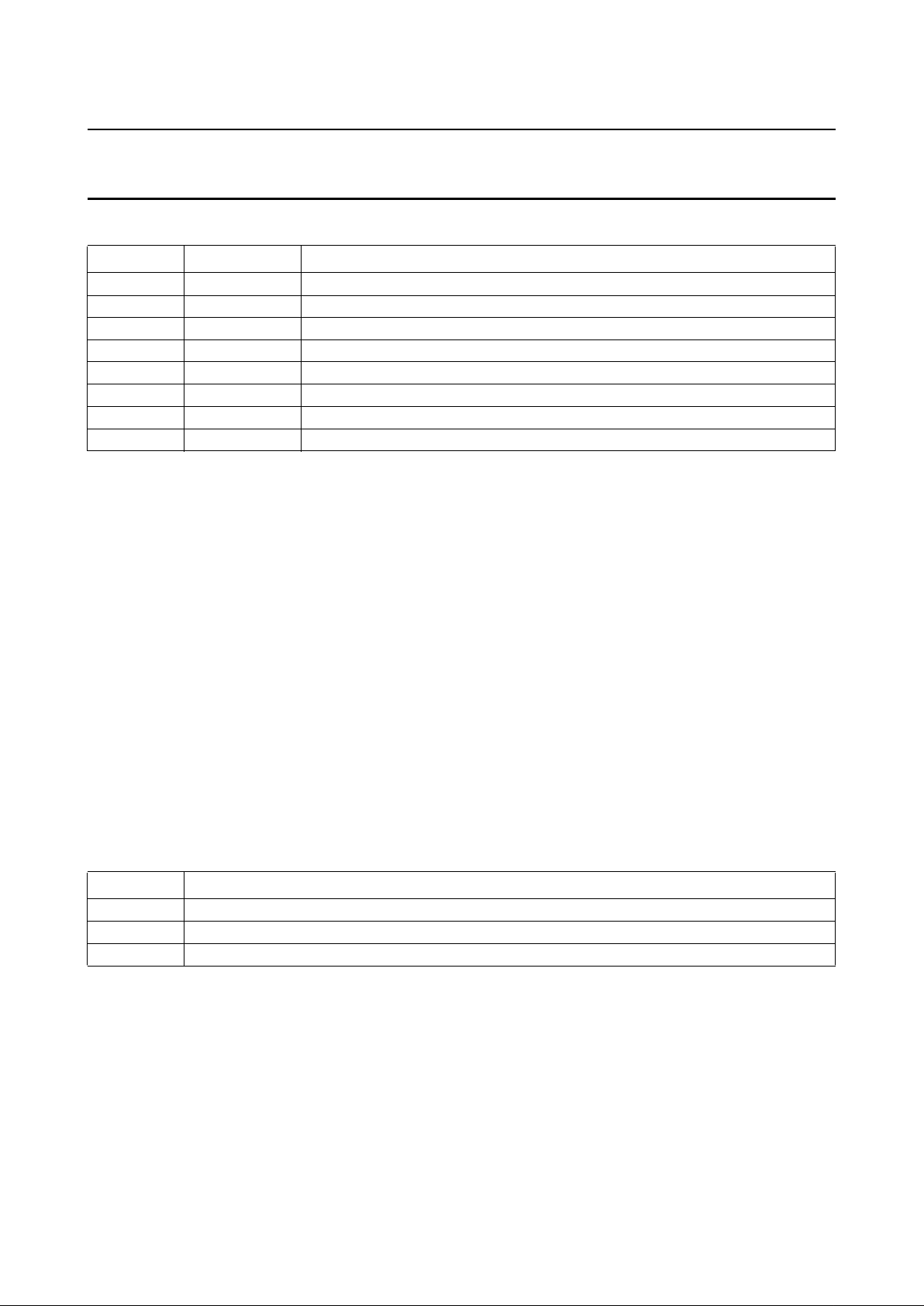
6.1.5 OUTPUT SELECT (OUTSEL)
This block is the ‘main’ output select function, possibly
functional on all outputs. Each output however has some
means to override this selection for its own output signal,
to implement extra features. Eight selections are possible
and they are shown in Table 1.
1995 Mar 21 10
Philips Semiconductors Preliminary specification
Audio processor for VHS hi-fi
and linear audio
TDA9614H
Table 1 Output select possibilities
Note
1. STEREO is the ‘standard’ setting, LEFT and RIGHT are for language selection. Using the tuner as input or output
signal (record or loop-through of audio FM) the VCR can automatically switch from stereo to left (language 1) when
a ‘dual language’ transmission is received. If the VCR is in playback mode and no hi-fi track is present (checking bit
AFOM via the I2C-bus or using the level at pin 11) the VCR can switch the output select to NORMAL (or let the IC
do this automatically by setting bit AUTN). If a hi-fi track is present the user may want to switch to LEFT and RIGHT
if the recording made was a ‘dual language’ recording.
Furthermore the user may want to switch from a hi-fi selection to NORMAL, e.g. when a complete audio remix has
been created on the linear track using ‘audio dubbing’ (see Section 6.7). ‘Audio dubbing’ can also be used to
re-record the linear track with e.g. only commentary. Combined playback of this commentary together with the
original hi-fi sound is then possible by means of a mix mode.
6.1.6 RF CONVERTER MUTE (RFCMUTE)
The RFC output is a mono output derived from the output select, its output signal can be muted.
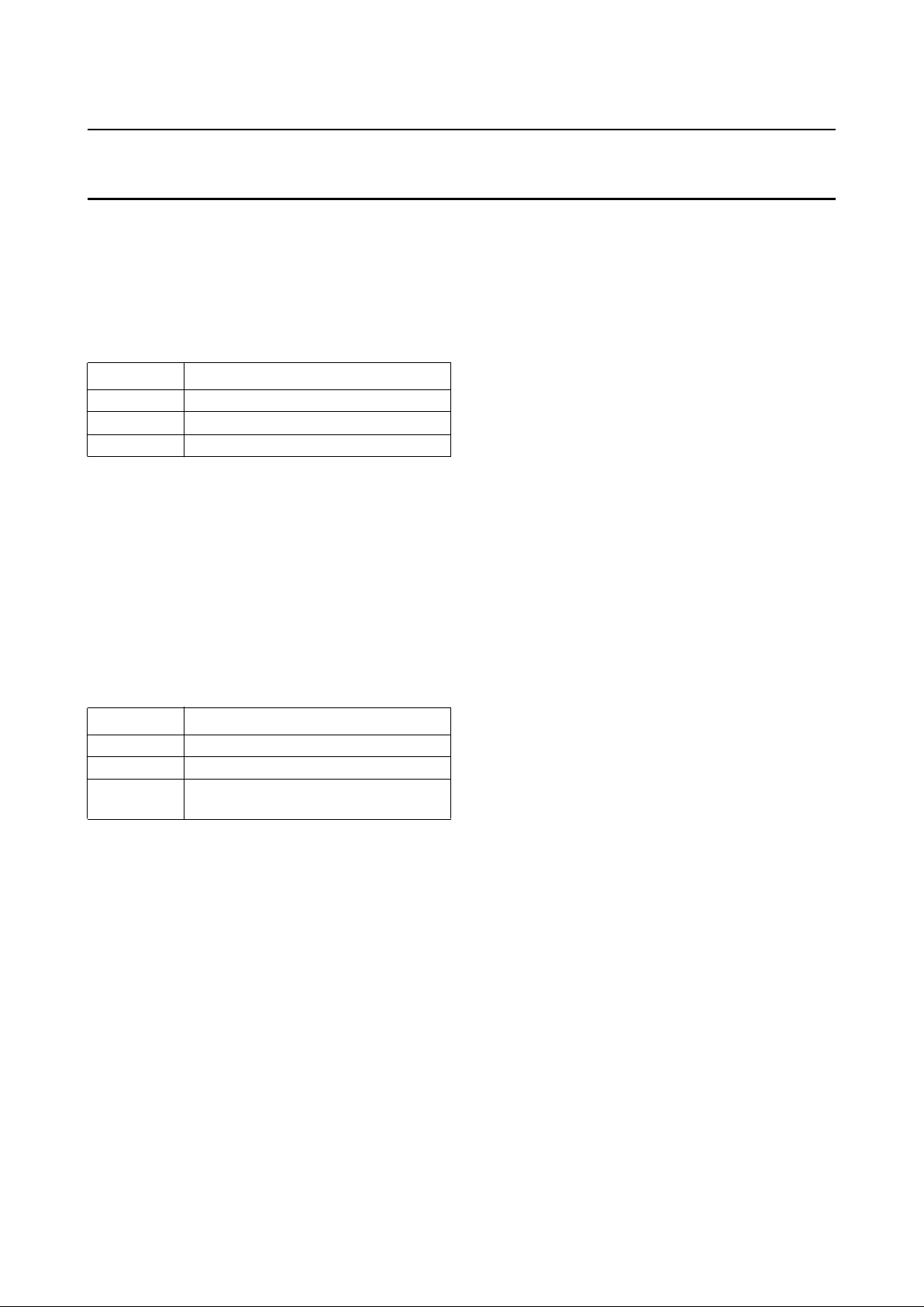
6.1.7 LINE SELECT (LINESEL)
The line output select is normally connected to both CINCH (hi-fi set) and television (SCART1). Normally the audio signal
from the output select will be available at this output, but three extra selections are possible and they are shown in
Table 2.
Table 2 Extra line select possibilities
Notes
1. A signal from a source at EXT2 (laser disc or second VCR) can be connected to a television set at line out. Because
this is a direct connection from the input to the line output buffers it is fully independent of any mode setting of the
IC. Connection of a ‘Pay-TV’ decoder box to EXT2 and using this selection together with selecting EXT1 in the
decoder select enables combined use of the decoder box by both TV and VCR. In Europe, use of the SCART
connector ‘status line’ can automatize this switching.
2. Direct audio connection from input EXT3. If the line 2 outputs and EXT3 inputs are not used for external connections
a built-in karaoke unit or sound processor can be inserted between line 2 and EXT3.
SELECTION REMARK DESCRIPTION
STEREO
(1)
hi-fi stereo audio FM output signal left and right channel
LEFT hi-fi left audio FM output signal left channel (language 1)
RIGHT hi-fi right audio FM output signal right channel (language 2)
NORMAL linear audio linear audio
NOR + ST linear and hi-fi mix of audio FM stereo and linear audio
NOR + L linear and left mix of audio FM left channel and linear audio
NOR + R linear and right mix of audio FM right channel and linear audio
MUTE mute
SELECTION DESCRIPTION
NORMAL linear audio, useful for monitoring during ‘audio dubbing’
EXT2
(1)
audio from input EXT2
EXT3
(2)
audio from input EXT3
1995 Mar 21 11
Philips Semiconductors Preliminary specification
Audio processor for VHS hi-fi
and linear audio
TDA9614H
6.1.8 DECODER SELECT (DECODESEL)
The line 2 output is normally connected to a decoder box
or e.g. a second VCR (SCART2). Normally the audio
signal from the output select will be available at this output,
but three extra selections are shown in Table 3.
Table 3 Extra decoder select possibilities
Notes
1. Enables the use of a decoder box (connected to line 2
[EXT2]) by the VCR.
2. Decoder box connection to television set
(See Section 6.1.7).
6.1.9 HEADPHONE SELECT (HPSEL)
The headphone output will normally carry the output select
signal, however three more selections are possible and
shown in Table 4.
Table 4 Extra headphone select possibilities
Note
1. The selections LEFT and RIGHT make it possible to
select a different language for the headphone as for
the line outputs. A possible implementation is to invert
always a language selection made at the output select.
6.1.10 H
EADPHONE VOLUME
The headphone volume control has a control range of
+16 dB to −47 dB in 1 dB steps and a full mute.
6.1.11 DC SELECT (DCSEL)
The VU meter output is normally connected to the
headphone select, but can also be switched to STEREO
(hi-fi stereo, before the output select). When using the
VU meter output signal to implement a ‘digital AGC’ (read
the level at the DC output, and adjust the VOLUME L/R
controls accordingly) it is necessary to have information of
SELECTION DESCRIPTION
TUNER
(1)
audio from input TUNER
EXT1
(2)
audio from input EXT1
EXT3 audio from input EXT3
SELECTION DESCRIPTION
LEFT
(1)
left hi-fi channel
RIGHT
(1)
right hi-fi channel
NORMAL linear audio, useful for monitoring the
recording by ‘audio dubbing’
both hi-fi audio channels, independent from the setting of
output or headphone select. For this mode the selection
STEREO can be made.
6.2 Linear audio circuits
6.2.1 RECORD/LOOP-THROUGH
The signal selected with the normal select can be level
controlled in the AGC block. If wanted this AGC can be
switched off using bit AGCN. The audio signal is thereafter
DC decoupled using a capacitor between pin 29 (LINOUT)
and pin 28 (LININ).
From here on the signal goes to the output select and (in
the event of record mode) to the record equalizer. The
record equalizer is a non-inverting amplifier with a gain of
+12 dB, consisting of an opamp with feedback resistors,
and acts as a pre-correction filter for the tape and head
characteristics. The inverting input of the opamp is
connected to pin 31 (RECEQ), its output to pin 33
(RECOUT). The circuit externally connected between
pin 31 and ground defines the transfer of the record
equalizer with equation:
Where: Z is the complex impedance of the external circuit.
Two equalizings can be used, switching additional circuitry
to ground with pin 30 (EQSW) in long play or extended
play (I2C-bus: LP = 1).
Instead of the hi-fi circuit, linear audio has two
loop-through modes:
• Loop-through playback
• Loop-through record.
The only difference between Loop-through record and
record is the RECOUT output, which is muted.
The LINREC output (pin 32) is used to drive the external
high-voltage switch and possibly the bias oscillator. The
LINREC voltage has a small internal delay to be
non-overlapping with the internal switching to playback
mode. This ensures that no bias voltage will appear at the
PBIN input while the IC is in playback mode.
6.2.2 P
LAYBACK
The signal coming from the head is amplified and can be
level controlled in 16 steps of 1 dB. This setting can be
used to adjust for spread or nominal difference in head
output level. Afterwards, the signal is frequency corrected
in the playback equalizer. This equalizer includes the two
standard VHS equalizing settings of 3180 and 120 µs
A 3.98
1200 Z
+( )
Z
------------------------------
×=

1995 Mar 21 12
Philips Semiconductors Preliminary specification
Audio processor for VHS hi-fi
and linear audio
TDA9614H
(standard play: LP = 0) and 3180 and 170 µs (Long Play:
LP = 1).
The signal is DC decoupled and routed to the output select
via pins 29 and 28. When switching to or from playback
the signal should be muted shortly using the Normal
Output Mute (NOM) to prevent audible clicks caused by
offset differences of the playback amplifier and AGC.
6.3 Audio FM circuits
6.3.1 RECORD/LOOP-THROUGH
After low-pass filtering and signal compression in the
Noise Reduction (NR) the audio signal is available at
AFNL and AFNR. Through a DC-decoupling capacitor the
compressed audio signal is fed to an audio clipper at
AFML and AFMR. Subsequently, the audio signal is
FM-modulated on a RF-carrier using an integrated
current-controlled oscillator (CCO). Each CCO (L and R)
requires an external resistor (RCCOL/R) for temperature
stability. Through automatic calibration both the oscillator
centre frequency and FM-deviation are adjusted. After
low-pass filtering and summation of the two RF-carriers,
the FM signal is available at FMOUT during record. During
loop-through the FMOUT pin is inactive.
The RAF pin reflects the status of the RAF-bit when it is
used as output pin. In this case it is meant to switch the
head amplifier between record and playback position. It
can also be used as an input pin to overrule the RAF-bit
thereby forcing the IC in record or playback/loop-through
position.
6.3.2 PLAYBACK
The two FM modulated RF carriers, presented at FMIN,
are fed to an AGC circuit. The AGC operates on the peak
level of the added BPF output signals. As a result, the input
signal of the BPFs is kept constant for FMIN voltages
>30 mV (RMS value) both carriers added. In this way the
dynamic range of the integrated BPFs is optimally used
over a large input signal range. Subsequently, the
RF carriers are bandpass filtered using two integrated
BPFs. These bandpass filters are automatically calibrated
as described in Section 6.3.3. An external resistor (RBPF)
is required for temperature stability.
The filtered input signals are fed to a limiter. The limiter
output signal is demodulated by means of a
PLL demodulator. The LF audio signal is fed through a
sample-and-hold circuit to suppress head-switching noise.
The demodulated audio is available at AFML and AFMR.
Through a decoupling capacitor the audio signal is applied
to an audio low-pass filter at AFNL and AFNR. The
low-pass filtered audio signal is expanded in the noise
reduction.
If the left channel carrier at FMIN falls below the mute level
of 4.2 mV (RMS value) the audio signal is muted in front of
the low-pass filter. This is achieved by comparing the left
channel level detector signal with an internal reference.
The mute timing is fixed by a capacitor at the CMUTE pin.
If the level at CMUTE rises above a certain threshold, the
PBMUTE bit is set. This will mute the audio signal. If bit
AUTN has been set, the output selection will automatically
switch to NORMAL mode. The left channel level detector
output is also available at pin ENVOUT. An AGC
correction voltage is added at this pin, such that the
ENVOUT voltage indicates the left channel FM-carrier
level even within the AGC-range. The ENVOUT voltage
can be used for auto-tracking of the FM-audio heads.
In the event of drop-outs in the incoming FM signal, the left
channel level detector is also used to activate the
sample-and-hold. This drop-out cancellation is only active
if bit DOC has been set.
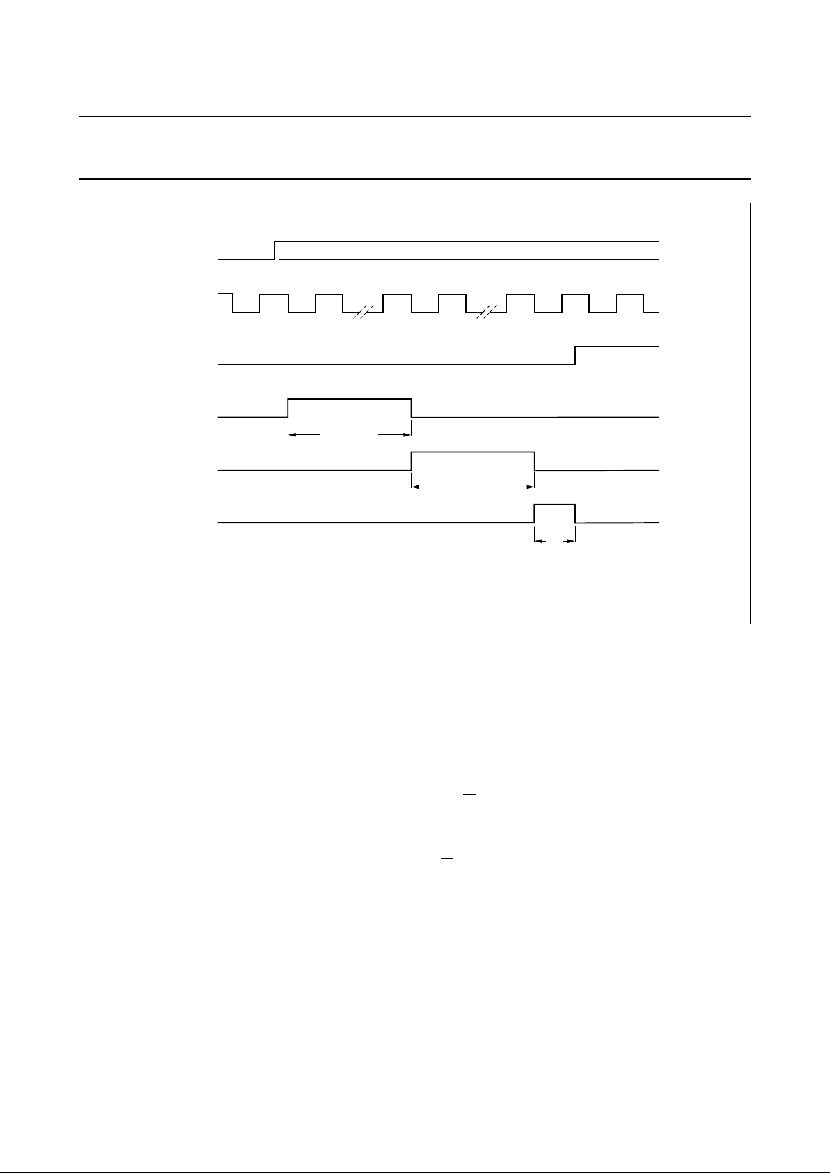
6.3.3 AUTOMATIC CALIBRATION
By means of bit CALS the two integrated oscillators and
bandpass filters can be calibrated in Loop-Through (LT) or
record (REC) mode. Normally this will be done after
start-up of the VCR. After setting of bit CALS the
calibration procedure is automatically executed as shown
in Fig.4. The calibration starts at the first negative edge of
HID after CALS has been set. During the LOW period of
HID (20 ms for PAL) the number of oscillator cycles is
compared to a certain value stored in a Read Only Memory
(ROM).
Therefore, the final oscillator frequency is proportional to
the inverse of the HID LOW-time. This means that an error
of 1 µs in the HID LOW-time will result in an additional
frequency error of approximately 100 Hz. The maximum
number of required HID cycles for one complete oscillator
calibration is six, which is equal to 240 ms.
After both oscillators have been calibrated the bandpass
filters are calibrated using the right channel oscillator as
reference frequency generator (1.6 MHz for PAL). This will
take <10 ms.
Bit CALR is set to 1 if the calibration has been executed
successfully. CALR is 0 if:
• A Power-On Reset (POR) has occurred.
• The calibration is running.
• The initial oscillator and bandpass frequencies are too
low or too high for a successful calibration.
1995 Mar 21 13
Philips Semiconductors Preliminary specification
Audio processor for VHS hi-fi
and linear audio
TDA9614H
Fig.4 Timing diagram of automatic calibration.
MBE281
max 240 ms
max 240 ms
max 10 ms
HID
CALS
LEFT
OSCILLATOR
RIGHT
OSCILLATOR
CALR
BANDPASS
FILTERS
If CALS is reset during CALR = 0, the calibration will be
stopped if it was not finished yet. If required, a new
calibration can be started using CALS.
WARNING: the IC should not be calibrated in a test or
standby mode.
6.3.4 PAL/NTSC MODE
Depending on bit NTSC the IC is calibrated in PAL or
NTSC mode using bit CALS. After an automatic calibration
the oscillator frequencies can be switched between PAL
and NTSC using bit NTSC. This centre frequency shift is
done without automatic calibration. During playback (PB)
or loop-through (LT) a change in bit NTSC will
automatically calibrate the bandpass filters again. This will
take <10 ms.
WARNING: A change of PB to REC, LT to REC and
PAL to NTSC should not be combined in one transmitted
byte. The PAL to NTSC transition should be preceded by
the PB to REC or LT to REC transition.
6.4 I2C-bus
The TDA9614H is controlled via the 2-wire I2C-bus, in
accordance with the I2C-bus specification. As slave
receiver for programming there is one module address,
with R/
W bit = 0, a subaddress byte and eight data bytes.
If more than one data byte follows the subaddress, these
bytes are stored in the successive registers by the
automatic address increment feature. As slave transmitter
(R/W bit = 1) there is one read byte.
1995 Mar 21 14
Philips Semiconductors Preliminary specification
Audio processor for VHS hi-fi
and linear audio
TDA9614H
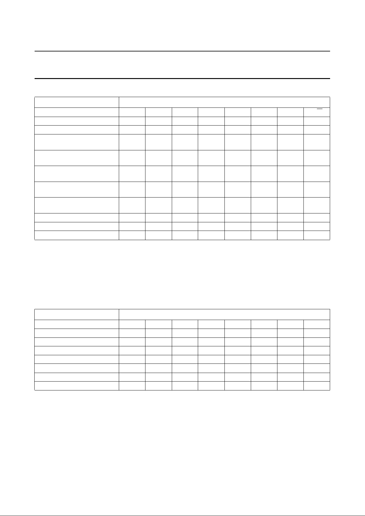
Table 5 TDA9614H addresses and data bytes
Note
1. These bits determine the subaddress.
6.5 Power-On Reset (POR); derived from digital supply voltage V
DDD
In the data byte descriptions [por] indicates the mode after POR. The status of the data bytes after POR is shown in
Table 6.
Table 6 Status of data bytes after POR
A POR occurrence is signalled by bit POR in the read byte (see Table 39).
NAME ADDRESS
Slave address byte 1 0 1 1 1 0 0 R/
W
Subaddress bytes 00 to 07 0 0 0 0 0 X
(1)
X
(1)
X
(1)
Control byte (subaddress 00) RAF IPAF AFOM NTSC RN IPN NOM LP
Main select byte
(subaddress 01)
IS2 IS1 IS0 NS1 NS0 OSL OSR OSN
Secondary select byte
(subaddress 02)
HSL HSR DCS RFCM LOS1 LOS0 DOS1 DOS0
Left volume byte
(subaddress 03)
0 VLM VL5 VL4 VL3 VL2 VL1 VL0
Right volume byte
(subaddress 04)
0 VRM VR5 VR4 VR3 VR2 VR1 VR0
Headphone volume byte
(subaddress 05)
0 VHM VH5 VH4 VH3 VH2 VH1 VH0
Install byte (subaddress 06) DEV1 DEV0 NPL3 NPL2 NPL1 NPL0 AUTN DOC
Test byte (subaddress 07) STBY CALS AGCN TST4 TST3 TST2 TST1 TST0
Read byte (address B9) CALR PAFM 1 POR 1 0 1 1
DATA BYTE ADDRESS
Control byte 0 1 1 0 0 1 1 0
Main select byte 0 0 0 0 0 1 1 0
Secondary select byte 1 1 0 0 0 0 0 0
Left volume byte 0 0 1 1 0 0 0 1
Right volume byte 0 0 1 1 0 0 0 1
Headphone volume byte 0 0 1 0 1 1 1 1
Install byte 0 1 0 1 1 1 0 1
Test byte 0 0 0 0 0 0 0 0
1995 Mar 21 15
Philips Semiconductors Preliminary specification
Audio processor for VHS hi-fi
and linear audio
TDA9614H
6.6 Control byte
Table 7 Bits of control byte
Table 8 Bits RAF and IPAF
Notes
1. The RAF bit can be overruled externally by applying a low-ohmic voltage to the RAF I/O (pin 12) either logic 0 or
logic 1 (0 or +5 V). The actual mode of the IC is determined by the level measured at this pin, enabling fast switching
between record and playback/loop-through.
2. The two record modes are equal, only differing in their reaction to forcing RAF LOW at the RAF I/O pin; the status of
the IPAF bit determines whether the IC is switched to the playback or loop-through mode.
Table 9 Bit AFOM
Note
1. Audio coming from the audio FM circuit is muted, either the signal from tape in playback or the loop-through signal
in record or loop-through modes.
Table 10 Bit NTSC
BIT DESCRIPTION
RAF Record Audio FM; see Table 8
IPAF Inverse Playback Audio FM; see Table 8
AFOM Audio FM Output Mute; see Table 9
NTSC NTSC; television standard; see Table 10
RN Record Normal; see Table 11
IPN Inverse Playback Normal; see Table 11
NOM Normal Output Mute; see Table 12
LP Long Play mode; see Table 13
RAF
(1)
IPAF MODE DESCRIPTION
0 0 playback NR and modem in playback mode
0 1 loop-through NR in record mode; modem not active [por]
1 0 record
(2)
NR and modem in record mode
1 1 record
(2)
NR and modem in record mode
AFOM MODE DESCRIPTION
0 − −
1 mute
(1)
output from audio FM (NR) circuit is muted [por]
NTSC MODE DESCRIPTION
0 PAL modem and BPF set to PAL carrier frequencies [por]
1 NTSC modem and BPF set to NTSC carrier frequencies
1995 Mar 21 16
Philips Semiconductors Preliminary specification
Audio processor for VHS hi-fi
and linear audio
TDA9614H
Table 11 Bits RN and IPN
Notes
1. Bit RN is output at LINREC (pin 32), which is used to drive an external (high voltage) head switch and possibly the
bias oscillator. The two loop-through modes are equal in signal flow, however they differ in the state of the head
switches (the internal switch at PBIN [pin 34] and the external head switch driven by pin LINREC).
2. Loop-through R is equal to record except for the RECOUT output (pin 33) which is muted.
Table 12 Bit NOM
Note
1. Audio coming from the linear audio circuit is muted, either the signal from tape in playback or the loop-through signal
in record or loop-through modes. To avoid clicks when changing the mode of the linear audio circuit to or from
playback, the output should be muted shortly, using this bit.
Table 13 Bit LP
RN
(1)
IPN MODE DESCRIPTION
0 0 playback linear audio circuit in playback mode
0 1 loop-through P linear audio circuit in loop-through mode (playback ready) [por]
1 0 loop-through R
(2)
linear audio circuit in loop-through mode (record ready)
1 1 record linear audio circuit in record mode
NOM MODE DESCRIPTION
0 − −
1 mute
(1)
output from linear audio circuit is muted [por]
LP MODE DESCRIPTION
0 SP Record and playback equalizing set for Standard Play [por].
Record equalization switch at EQSW (pin 30) and playback equalization switch at RESSW
(pin 35) are open (high impedance). The internal playback equalizing is 3180 and 120 µs.
It can be changed to 2544 and 96 µs by selecting test number 31 (see Section 6.12).
1 LP Record and playback equalizing set for Long Play.
Record equalization switch at EQSW (pin 30) and playback equalization switch at RESSW
(pin 35) are closed. The internal playback equalizing is 3180 and 170 µs. It can be
changed to 2731 and 146 µs by selecting test number 31 (see Section 6.12).
1995 Mar 21 17
Philips Semiconductors Preliminary specification
Audio processor for VHS hi-fi
and linear audio
TDA9614H
6.7 Main select byte
Table 14 Bits of main select byte
Table 15 Bits IS2 to IS0; note 1
Notes
1. With bits IS2 to IS0, the stereo input signal is selected which is led to the hi-fi processing. One out of five stereo
sources can be selected. The five stereo inputs differ in their connectivity; with bits NS1 and NS0 tuner left
(TUNL; pin 2) can be selected as linear audio input source, with bits LOS1 and LOS0 Normal, Ext2 and Ext3 are
directly connectable to Line out and to DOS1 and DOS0 Tuner, Ext1 and Ext3 are directly connectable to decoder
out (2nd Line Out).
2. Remark: when using the selections Normal or Dub Mix be aware of signal loops (which should be avoided) because
this can lead to large audio oscillations.
3. The selection Dub Mix is a special function in which a mono signal derived from the Ext3 inputs
(1⁄2EXT3L +1⁄2EXT3R) is led to the left input and a mono signal derived from the audio FM output (1⁄2L +1⁄2R) is led
to the right input channel. This function can be used for audio dubbing using the volume controls as a mixing desk.
Table 16 Bits NS1 and NS0; note 1
Note
1. With bits NS1 and NS0 the input signal is selected for the linear audio circuit. When a stereo input source is selected,
a mono signal is made by adding the left and right channel. Furthermore two independent selections can be made
(the mono input SAP or the left channel of tuner e.g. for dual language). If in the volume mode the built-in AGC circuit
is switched off by using bit AGCN, the audio level can be controlled by the left and right volume controls
(VLx and VRx).
BIT DESCRIPTION
IS2 to IS0 Input Select 2 to Input Select 0; see Table 15
NS1 and NS0 Normal Select 1 and Normal Select 0; see Table 16
OSL Output Select Left; see Table 17
OSR Output Select Right; see Table 17
OSN Output Select Normal; see Table 17
IS2 IS1 IS0 MODE SELECTED INPUT SOURCE
0 0 0 Tuner TUNL and TUNR [por]
0 0 1 Cinch CINL and CINR
0 1 0 Ext1 EXT1L and EXT1R (e.g. SCART1; TV connector)
0 1 1 Ext2 EXT2L and EXT2R (e.g. SCART2; decoder connector)
1 0 0 Ext3 EXT3L and EXT3R (e.g. front cinch)
1 0 1 SAP additional mono input (SAP; pin 1)
1 1 0 Normal
(2)
output from linear audio (LININ; pin 28)
1 1 1 Dub Mix
(2)(3)
mixing of EXT3 input with hi-fi output signal
NS1 NS0 MODE DESCRIPTION
0 0 Input linear audio input source is equal to hi-fi input [por]
0 1 Volume linear audio input source is equal to hi-fi input, inclusive volume control
1 0 SAP additional mono input (SAP; pin 1) is selected
1 1 Tuner L left channel of tuner input is selected
1995 Mar 21 18
Philips Semiconductors Preliminary specification
Audio processor for VHS hi-fi
and linear audio
TDA9614H
Table 17 Bits OSL, OSR and OSN; note 1
Note
1. The bits OSL, OSR and OSN provide eight output select functions. LEFT and RIGHT are the left and right hi-fi
channels; NORMAL is the linear audio channel (LININ; pin 28). This selection is normally output at line out (LINEL
and LINER), RFCOUT (pin 18), decoder out (LINE2L and LINE2R), headphone out (HPOUTL and HPOUTR) and
DC out (DCOUTL and DCOUTR). However line out can be overruled by bits LOS1 and LOS0; decoder out can be
overruled by bits DOS1 and DOS0, headphone out (and DC out) can be overruled by bits HSL and HSR and DC out
can be overruled by bit DCS.
Remark: if AUTN = 1 (see Section 6.11) the output select modes stereo, left and right will be forced to normal as long
as the audio FM circuit is in playback mode and the internal PB mute signal is generated (no hi-fi track on tape). The
status of this internal mute signal can be read by bit PAFM (see Section 6.13).
6.8 Secondary select byte
Table 18 Bits of secondary select byte
OSL OSR OSN MODE DESCRIPTION
1 1 0 stereo LEFT at left channel; RIGHT at right channel [por].
1 0 0 left LEFT at both left and right channels.
0 1 0 right RIGHT at both left and right channels.
0 0 0 mute No selection.
1 1 1 mixed stereo LEFT + NORMAL added at left channel; RIGHT + NORMAL added at
right channel.
1 0 1 mixed left LEFT + NORMAL added at both left and right channels.
0 1 1 mixed right RIGHT + NORMAL added at both left and right channels.
0 0 1 normal NORMAL (is linear audio) at both left and right channels.
BIT DESCRIPTION
HSL Headphone Select Left; see Table 19
HSR Headphone Select Right; see Table 19
DCS DC Select; see Table 20
RFCM RFC Mute; see Table 21
LOS1 and LOS0 Line Output Select 1 and Line Output Select 0; see Table 22
DOS1 and DOS0 Decoder Output Select 1 and Decoder Output Select 0; see Table 23
 Loading...