

Philips TDA9610H Datasheet

INTEGRATED CIRCUITS
DATA SH EET
TDA9610H
Audio FM processor for VHS hi-fi
audio
Product specification
Supersedes data of March 1993
File under Integrated Circuits, IC02
Philips Semiconductors
1995 Mar 21

Philips Semiconductors Product specification
Audio FM processor for VHS hi-fi audio TDA9610H
FEATURES
• Integrated High Frequency (HF) low-pass filter (LPF)
and summator
• Low-noise Phase-Locked Loop (PLL) FM (de)modulator
• Low-distortion sample-and-hold switching noise
suppressor
• Integrated audio low-pass filter
• 4 stereo input selectors (left [L] and right [R] channel):
– EXT1L and EXT1R
– EXT2L and EXT2R
– CINL and CINR
– TUNL and TUNR
• Additional mono inputs for linear audio: EXN1 and EXN2
• DC output for VU meter drive
• Direct headphone drive
• Linear input/linear output
• Modulator output with overload Automatic Gain
Control (AGC)
• RAF (Record Audio FM) for head amplifier control
• Power-down mode facility
2
C-bus control of:
• I
– line input volume
– headphone output volume
– input/output selector
– PAL/NTSC mode
• E-E performance (record + playback):
– Total Harmonic Distortion (THD): 0.05%
(−8 dBV, 1 kHz)
– linearity error: 0.1 dB (−88 dBV)
– noise: −93 dBV (20 Hz to 20 kHz).
GENERAL DESCRIPTION
The TDA9610H is a dual audio FM processing IC for VHS
hi-fi audio, digitally controlled via the I
2
C-bus. The
FM (de)modulator and peak noise reduction functions are
highly integrated, resulting in few external components
and adjustments.
In addition special functions for audio editing, mixing and
dubbing have been implemented.
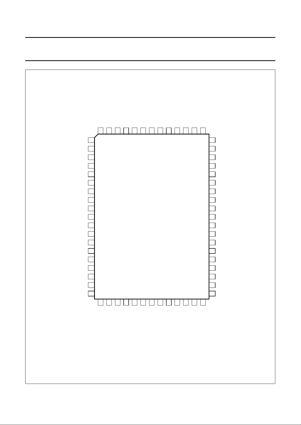
ORDERING INFORMATION
PACKAGE
TYPE NUMBER
NAME DESCRIPTION VERSION
TDA9610H QFP64
(1)
plastic quad flat package; 64 leads (lead length 1.95 mm);
body 14 × 20 × 2.8 mm
Note
1. When using IR reflow soldering it is recommended that the Drypack instructions in the
Handbook”
(order number 9398 510 63011) are followed.
1995 Mar 21 2
SOT319-2
“Quality Reference

Philips Semiconductors Product specification
Audio FM processor for VHS hi-fi audio TDA9610H
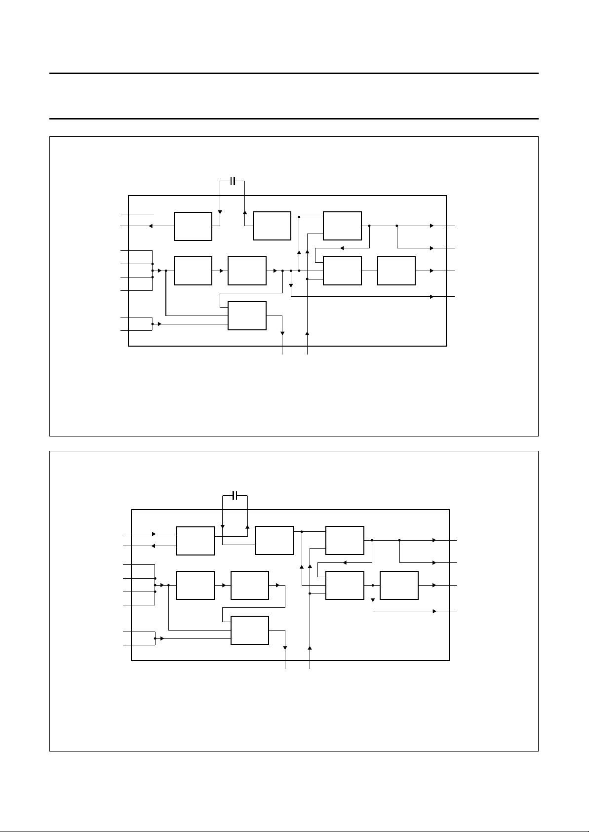
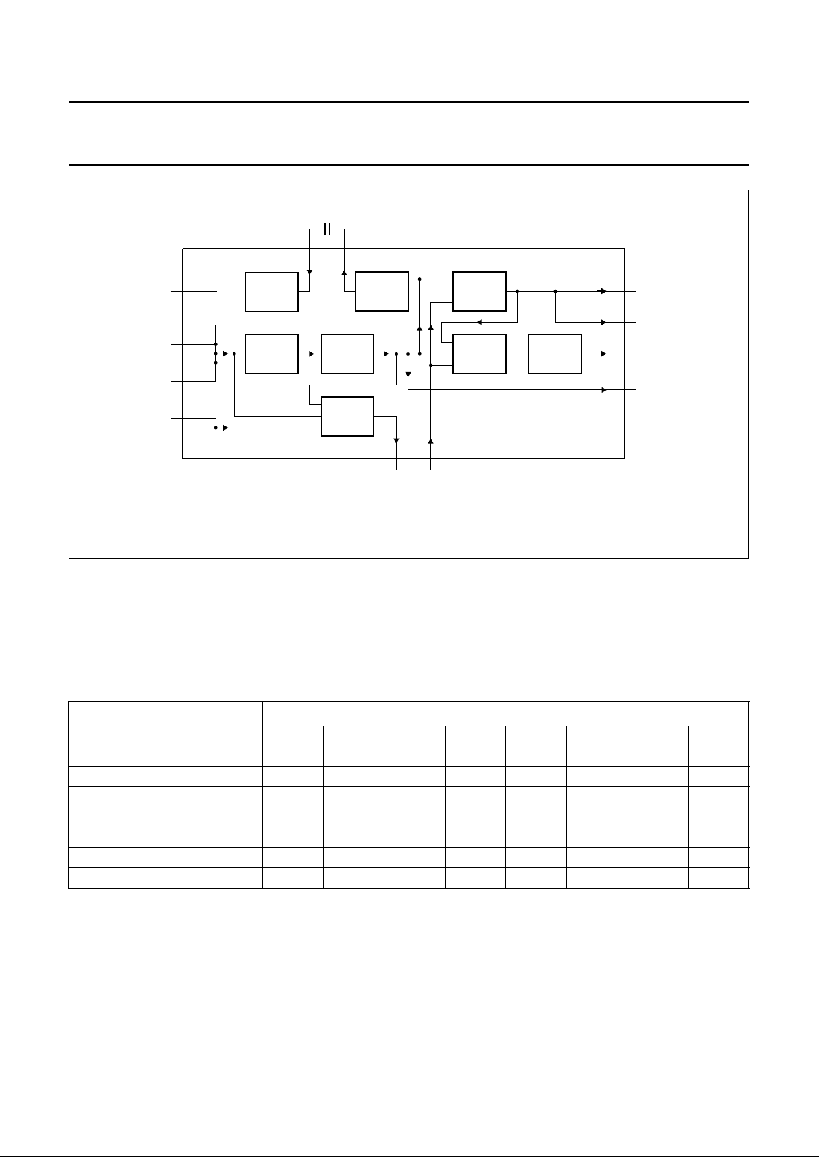
BLOCK DIAGRAM
LINER
DCOUTL
31
DCOUTR
32
HPOUTL
22
HPOUTR
23
LINEL
27
28
MODOUT
30
MODAGC
29
MRC083 - 1
DETLRFIX
RECTL
EMPHL
DCREFL
DCFBL
RVARAFOUTR
AFINR
AFOUTL
AFINL
SSD
V
SDASCLRAF
35 36 37 38 39
25 24
GAIN
2 50 49
NOISE REDUCTION
IPAF + RAF
ADJUST
2
I C
VH4 to VH0
HSF
HSL and HSR
LPF
AUDIO
SAOL,
SAOR,
SAON
LPF
AUDIO
NSS, NSH
and NSL
1834
XS
33
NOISE REDUCTION
46 45 44 43 42
47
658 3 4 48 527109
n.c. XS
LININ
DCREFR RECTR
handbook, full pagewidth
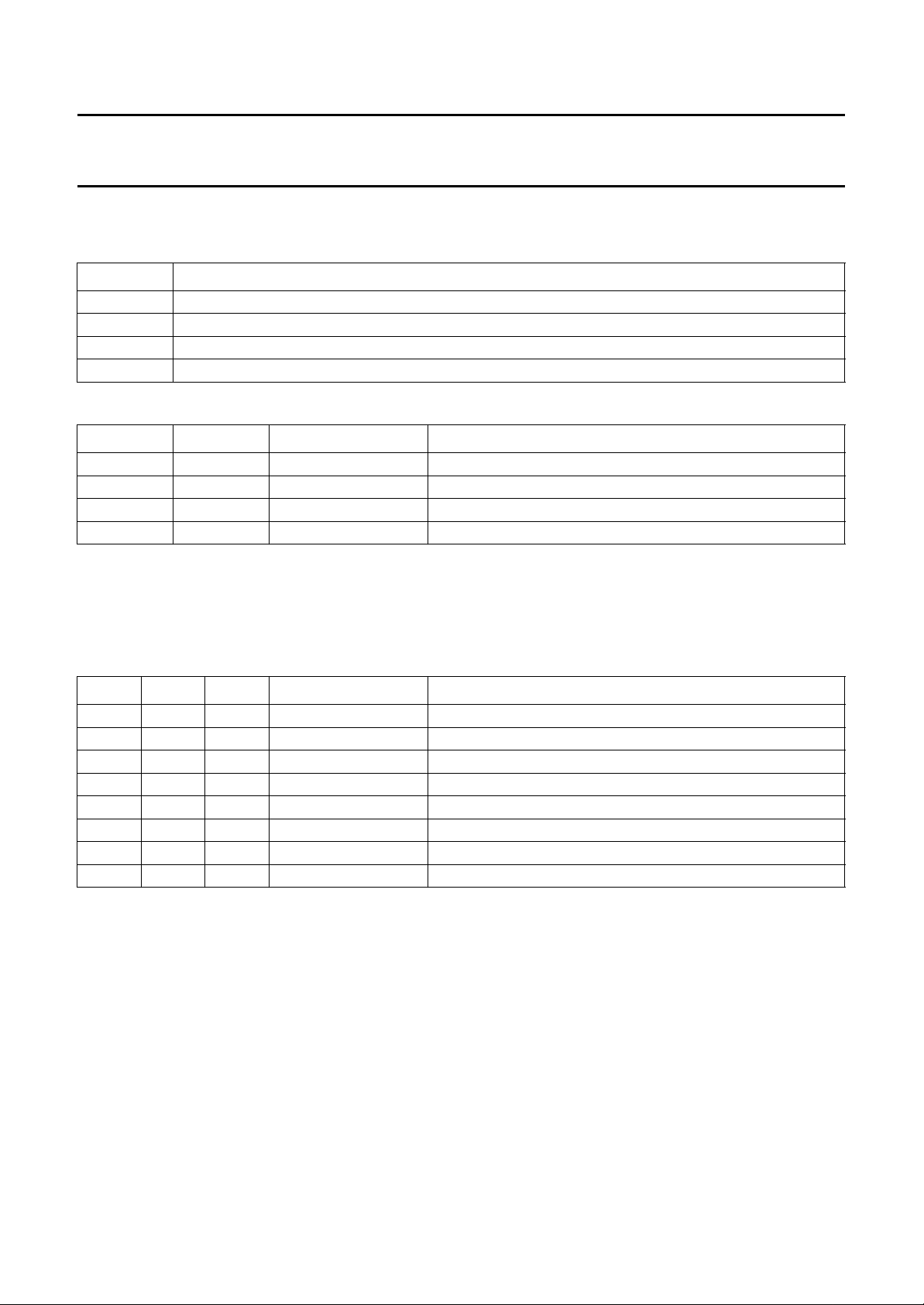
Fig.1 Block diagram.
AND-
AND-
HOLD
HOLD
SAMPLE-
SAMPLE-
MUTE
ENVOUT
HID
FADJL
ref
V
SSA1
V
SSH
V
DDA1
V
DDH
V
SSA2
V
DDA2
V
DDD
V
64
4041211920595713 51 11 12 14 17 16 15 1
MUTE
ONE
SCHOT
ref
SUPPLY AND V
NTSC
LOOP
LEVEL
60
FILTER
DETECT
NTSC
AUDIO
CLIPPER
61
ϕ
HF
LIMITER
FMINL
1.3 MHz
1.4 MHz
RAF
CCO
CCO
1.7 MHz
1.8 MHz
HF
LPF
56
FMOUT
ϕ
HF
LPF
HF
55
FMINR
1995 Mar 21 3
AUDIO
CLIPPER
LIMITER
VL5 to VL0
LOOP
FILTER
VR5 to VR0
TDA9610H
54
n.c.62n.c.63n.c.
ISH and ISL
53
FADJR TUNL TUNR CINL CINR EXT1L EXT1R EXT2L EXT2R EXN1 EXN2 LINOUT DCFBR EMPHR DETR
2658
i.c. i.c.
Philips Semiconductors Product specification
Audio FM processor for VHS hi-fi audio TDA9610H
PINNING
SYMBOL PIN DESCRIPTION
AFINL 1 audio input for either audio clipper (record) or noise reduction (playback) of left
channel
AFOUTL 2 audio output from either sample-and-hold (playback) or noise reduction (record and
loop-through) of left channel
EXT2L 3 input selector for left channel
EXT2R 4 input selector for right channel
EXT1L 5 input selector for left channel
EXT1R 6 input selector for right channel
CINL 7 input selector for left channel
CINR 8 input selector for right channel
TUNL 9 input selector for left channel
TUNR 10 input selector for right channel
ENVOUT 11 level detector output; external capacitor required for filtering
MUTE 12 mute timing; external capacitor required for timing playback mute
V
DDD
RAF 14 overrule the I
V
SSD
SDA 16 I
SCL 17 I
XS 18 auxiliary switch; digital output controlled by I
V
DDA1
V
DDH
V
SSH
HPOUTL 22 headphone drive output left
HPOUTR 23 headphone drive output right
RVAR 24 gain adjustment of noise reduction by means of a resistor to ground
RFIX 25 fixed bias current generation circuit by using an external 100 kΩ resistor to ground
i.c. 26 pin internally connected to die pad; preferably connected to ground
LINEL 27 line output left
LINER 28 line output right
MODAGC 29 RF modulator AGC-time constant
MODOUT 30 RF modulator drive output
DCOUTL 31 VU meter drive output left
DCOUTR 32 VU meter drive output right
LININ 33 linear input
n.c. 34 not connected
DCFBL 35 DC feedback left
DCREFL 36 DC reference left
EMPHL 37 total emphasis left (20 to 240 µs)
13 digital supply voltage (+5 V)
2
C-bit RAF input or record/playback switch drive output for head
amplifier control
15 I2C-bus digital ground
2
C-bus data input
2
C-bus clock input
19 analog supply voltage 1 (+12 V)
20 headphone supply voltage (+12 V)
21 headphone ground
2
C-bit XS
1995 Mar 21 4
Philips Semiconductors Product specification
Audio FM processor for VHS hi-fi audio TDA9610H
SYMBOL PIN DESCRIPTION
RECTL 38 rectifier DC decoupling left
DETL 39 attack/recovery timing left
V
ref
V
SSA1
DETR 42 attack/recovery timing right
RECTR 43 rectifier DC decoupling right
EMPHR 44 total emphasis right (20 to 240 µs)
DCREFR 45 DC reference right
DCFBR 46 DC feedback left
LINOUT 47 linear output
EXN1 48 EXN input (external normal input); mono input selectable to linear output
AFOUTR 49 audio output from either sample-and-hold (playback) or noise reduction (record and
AFINR 50 audio input for either audio clipper (record) or noise reduction (playback) of right
HID 51 head identification pulse input for sample-and-hold circuits
EXN2 52 EXN input (external normal input); mono input selectable to linear output
FADJR 53 frequency adjustment of right channel oscillator by means of a variable resistor
n.c. 54 not connected; preferably connected to ground
FMINR 55 1.7 to 1.8 MHz input for limiter
FMOUT 56 FM output
V
DDA2
i.c. 58 pin internally connected to die pad; preferably connected to ground
V
SSA2
NTSC 60 digital output controlled by I
FMINL 61 1.3 to 1.4 MHz input for limiter
n.c. 62 not connected; preferably connected to ground
n.c. 63 not connected; preferably connected to ground
FADJL 64 frequency adjustment of left channel oscillator by means of a variable resistor
40 noise filtering of 3.8 V reference voltage; external capacitor required for filtering
41 analog ground for LF circuits
loop-through) of right channel
channel
57 analog supply voltage (+5 V)
59 analog ground for HF circuits
2
C-bit NTSC
1995 Mar 21 5
Philips Semiconductors Product specification
Audio FM processor for VHS hi-fi audio TDA9610H
handbook, full pagewidth
AFINL
AFOUTL
EXT2L
EXT2R
EXT1L
EXT1R
CINL
CINR
TUNL
TUNR
ENVOUT
MUTE
V
DDD
RAF
V
SSD
SDA
SCL
XS
V
DDA1
FADJL
n.c.
n.c.
FMINL
64
63
62
61
1
2
3
4
5
6
7
8
9
10
11
12
13
14
15
16
17
18
19
SSA2VDDA2
NTSC
V
60
59
TDA9610H
i.c.
58
FMOUT
FMINR
57
56
55
n.c.
54
FADJR
53
EXN2
52
51
50
49
48
47
46
45
44
43
42
41
40
39
38
37
36
35
34
33
HID
AFINR
AFOUTR
EXN1
LINOUT
DCFBR
DCREFR
EMPHR
RECTR
DETR
V
SSA1
V
ref
DETL
RECTL
EMPHL
DCREFL
DCFBL
n.c.
LININ
20
21
22
23
24
25
SSH
DDH
V
V
HPOUTL
HPOUTR
RVAR
RFIX
Fig.2 Pin configuration.
1995 Mar 21 6
26
i.c.
27
LINEL
28
LINER
29
30
MODOUT
MODAGC
31
32
DCOUTL
DCOUTR
MKA319 - 1

Philips Semiconductors Product specification
Audio FM processor for VHS hi-fi audio TDA9610H
FUNCTIONAL DESCRIPTION
The IC is intended for use within the audio FM system of
VHS video recorders. Three modes of operation can be
distinguished:
• Record mode
• Playback mode
• Loop-through mode.
Switching and control of the three modes is done by the
I2C-bus.
Record mode
The audio signal, selected from the four stereo audio
inputs (EXT1L, EXT1R, EXT2L, EXT2R, CINL, CINR,
TUNL and TUNR), is fed to the volume control stage
(separate for left [L] and right [R]). The information for
LINOUT is, after summing of L and R, derived from either
one of the four stereo inputs or the volume control output
or one of the mono inputs (EXN1 and EXN2). After the
Low-Pass Filter (LPF) and signal compression in the noise
reduction (NR) and filter block the audio signal is available
at AFOUTL and AFOUTR. The compressed signal is now
FM modulated on a RF carrier in the PLL block. After
low-pass filtering and summation of both RF carriers
(L and R) the signal is available at FMOUT.
The output select block offers the possibility to choose
eight different audio signal modes:
1. Stereo.
2. Left.
3. Right.
4. Mono.
5. Normal.
6. Mixed stereo (stereo + LININ).
7. Mixed left (left + LININ).
8. Mixed right (right + LININ).
The headphone select block offers the possibility to
choose either the output select signal or four independent
audio signal modes (stereo, left, right and normal) for the
output stages HPOUTL and HPOUTR.
HPOUTL and HPOUTR, with common volume control for
L and R, is suitable for direct headphone drive.
DCOUTL and DCOUTR are intended for VU meter drive.
It is connected to the selected stereo audio input after the
volume control block. The output signal at
DCOUTL and DCOUTR is proportional to the square root
of the recorded audio signal (see Fig.3).
Playback mode
The two FM modulated RF carriers, present at the two
FMINL and FMINR inputs after being band-pass filtered,
are demodulated in the PLL block. The LF audio signal is
fed through a sample-and-hold circuit to suppress
head-switching noise. The demodulated audio signal is
available at AFOUTL and AFOUTR. The audio signal is
low-pass filtered and expanded in the noise reduction (NR)
and filter block. The resulting audio signal is available after
the output and headphone select blocks for all four output
stages (LINEL, LINER, MODOUT, HPOUTL, HPOUTR,
DCOUTL and DCOUTR). The functionality of the output
and headphone select blocks is identical to the record
mode. During playback DCOUTL and DCOUTR are
connected to the headphone select block.
The functionality of the input and normal select blocks is
also identical to record mode (see Fig.3), which offers the
possibility to control (other) audio signals independently
for LINOUT (see Fig.4).
Loop-through mode
This mode is similar to the record mode (see Fig.3), except
for the FMOUT pin, which is inactive, and the RAF output
which is active LOW (see Fig.5).
These audio signal modes are selectable for the output
stages LINEL, LINER and MODOUT. The standard audio
output is LINEL and LINER, e.g. for SCART output.
MODOUT is a mono audio output, with an
overload-protecting AGC, to drive an external
RF modulator.
1995 Mar 21 7
Philips Semiconductors Product specification
Audio FM processor for VHS hi-fi audio TDA9610H
AFINL/R AFOUTL/R
2,491,50
VOLUME
CONTROL
NORMAL
SELECT
NR
AND
FILTER
47 33
LINOUT LININ
OUTPUT
SELECT
HEAD-
PHONE
SELECT
VOLUME
CONTROL
TDA9610H
27,28
30
22,23
31,32
MKA359 - 1
LINEL/R
MODOUT
HPOUTL/R
DCOUTL/R
FMINL/R
FMOUT
EXT2L/R
EXT1L/R
CINL/R
TUNL/R
EXN1
EXN2
61,55
56
3,4
5,6
7,8
9,10
48
52
PLL
INPUT
SELECT
FMINL/R
FMOUT
EXT2L/R
EXT1L/R
CINL/R
TUNL/R
EXN1
EXN2
61,55
56
3,4
5,6
7,8
9,10
48
52
Fig.3 Record mode.
AFINL/R AFOUTL/R
2,491,50
PLL
INPUT
SELECT
VOLUME
CONTROL
NORMAL
SELECT
NR
AND
FILTER
47 33
LINOUT LININ
OUTPUT
SELECT
HEAD-
PHONE
SELECT
VOLUME
CONTROL
TDA9610H
27,28
30
22,23
31,32
MKA360 - 1
LINEL/R
MODOUT
HPOUTL/R
DCOUTL/R
Fig.4 Playback mode.
1995 Mar 21 8
Philips Semiconductors Product specification
Audio FM processor for VHS hi-fi audio TDA9610H
AFINL/R AFOUTL/R
2,491,50
VOLUME
CONTROL
NORMAL
SELECT
NR
AND
FILTER
47 33
LINOUT LININ
OUTPUT
SELECT
HEAD-
PHONE
SELECT
VOLUME
CONTROL
TDA9610H
27,28
30
22,23
31,32
MKA361 - 1
LINEL/R
MODOUT
HPOUTL/R
DCOUTL/R
FMINL/R
FMOUT
EXT2L/R
EXT1L/R
CINL/R
TUNL/R
EXN1
EXN2
61,55
56
3,4
5,6
7,8
9,10
48
52
PLL
INPUT
SELECT
Fig.5 Loop-through mode.
I2C-bus
Bus specification in accordance with I2C-bus specification. Full details of the I2C-bus are given in the document
I2C-bus and how to use it”
. This document may be ordered using the code 9398 393 40011.
“The
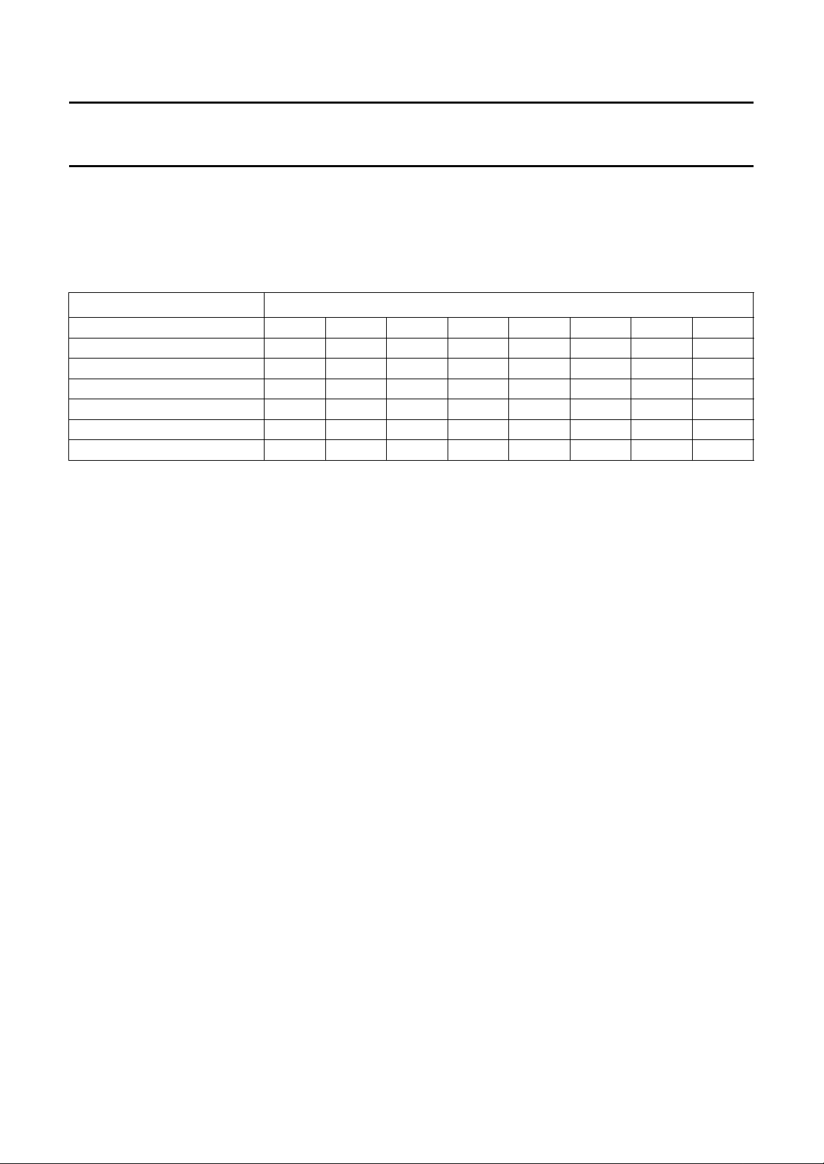
The address and data bytes of the TDA9610H are shown in Table 1.
Table 1 TDA9610H address and data bytes
NAME ADDRESS
Slave address (B8) 1 0 111000
Control byte
Select byte
Input byte
Function byte
(1)
(2)
(3)
(4)
Record volume left byte
Record volume right byte
Headphone volume byte
(5)
(5)
(6)
0 0 0 IPAF RAF NTSC PAFM MUTE
0 0 1 SAOL SAOR SAON HSF NSS
0 1 1 0 ISH ISL NSH NSL
0 1 1 1 HSL HSR XS TEST
1 0 VL5 VL4 VL3 VL2 VL1 VL0
1 1 VR5 VR4 VR3 VR2 VR1 VR0
0 1 0 VH4 VH3 VH2 VH1 VH0
Notes
1. See Section “Control byte”.
2. See Section “Select byte”.
3. See Section “Input byte”.
4. See Section “Function byte”.
5. See Section “Record volume left and right byte”.
6. See Section “Headphone volume byte”.
1995 Mar 21 9
Philips Semiconductors Product specification
Audio FM processor for VHS hi-fi audio TDA9610H
Power-On Reset (POR); derived from digital supply V
DDD
In the data byte descriptions [por] indicates the mode after POR.
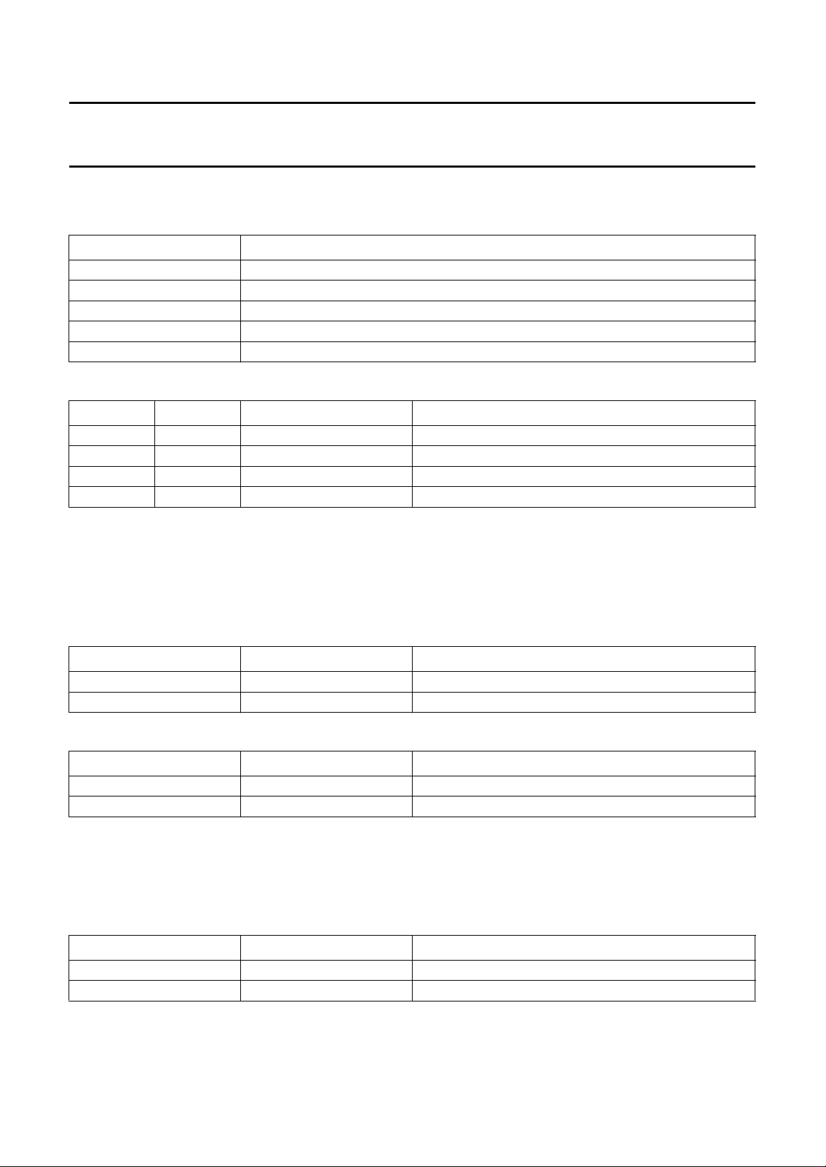
The status of the data bytes after POR is shown in Table 2.
Table 2 TDA9610H address and data bytes after POR
NAME ADDRESS
Control byte
Select byte
Input byte
Function byte
(1)
(2)
(3)
(4)
Record volume left byte
Record volume right byte
Headphone volume byte
(5)
(5)
(6)
00010001
00111000
01100000
01110000
10110001
11110001
01010111
Notes
1. See Section “Control byte”.
2. See Section “Select byte”.
3. See Section “Input byte”.
4. See Section “Function byte”.
5. See Section “Record volume left and right byte”.
6. See Section “Headphone volume byte”.
1995 Mar 21 10
Philips Semiconductors Product specification
Audio FM processor for VHS hi-fi audio TDA9610H
Control byte
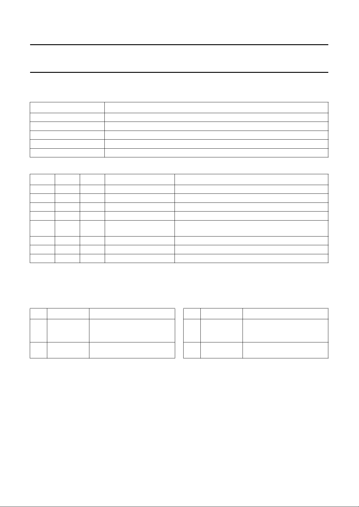
Table 3 Bits of control byte
BIT DESCRIPTION
IPAF Inverse Playback Audio FM; see Table 4
RAF Record Audio FM; see Table 4
NTSC National Television Standards Committee; television standard; see Table 5
PAFM Playback Audio FM Mute; see Table 6
MUTE Mute; see Table 7
Table 4 Bits IPAF and RAF
IPAF RAF
(1)
0 0 playback NR and modem in playback mode
1 0 loop-through NR in record mode; modem not active [por]
0 1 record
1 1 record
MODE DESCRIPTION
(2)
(2)
NR and modem in record mode
NR and modem in record mode
Notes
1. The RAF bit can be overruled externally by applying a low-ohmic voltage to the RAF I/O (pin 14) either logic 0 or
logic 1 (0 or +5 V). The actual mode of the IC is determined by the level measured at this pin.
2. The two record modes are equal, only differing in their reaction to forcing RAF LOW at the RAF I/O pin; the status of
the IPAF bit determines whether the IC is switched to the playback or loop-through mode.
Table 5 Bit NTSC
NTSC MODE DESCRIPTION
0 PAL modem set to PAL carrier frequencies [por]
1 NTSC modem set to NTSC carrier frequencies
Table 6 Bit PAFM
PAFM
(1)
MODE DESCRIPTION
0 −
1 PB mute the signal from the modem is muted in playback mode
Note
1. Bit PAFM has the same effect as the internally generated mute signal from the modem part when no FM carrier is
detected during playback mode. If one (or both) of these signals is HIGH, the audio signal coming from the modem
is muted.
Table 7 Bit MUTE
MUTE MODE DESCRIPTION
0 −
1 full mute all audio outputs are muted [por]
1995 Mar 21 11
Philips Semiconductors Product specification
Audio FM processor for VHS hi-fi audio TDA9610H
Select byte
Table 8 Bits of select byte
BIT DESCRIPTION
SAOL Select Audio Output Left; see Table 9
SAOR Select Audio Output Right; see Table 9
SAON Select Audio Output Normal; see Table 9
HSF Headphone Select Function; see Table 10
NSS Normal Special Select; see Table 11
Table 9 Bits SAOL, SAOR and SAON; note 1
SAOL SAOR SAON MODE DESCRIPTION
1 1 0 stereo left at LINEL, right at LINER [por]
1 0 0 left left at both LINEL and LINER
0 1 0 right right at both LINEL and LINER
0 0 0 mono left + right added at both LINEL and LINER (hi-fi mono)
1 1 1 mixed stereo left + normal added at LINEL, right + normal added at
LINER
1 0 1 mixed left left + normal added at both LINEL and LINER
0 1 1 mixed right right + normal added at both LINEL and LINER
0 0 1 normal normal (is linear audio) at both LINEL and LINER
Note
1. The bits SAOL, SAOR and SAON provide eight output select functions, left and right are the left and right hi-fi
channels, normal is the conventional audio channel, linear audio input (LININ; pin 33).
Table 10 Bit HSF; note 1
HSF MODE DESCRIPTION
0 − headphone output signals
identical to line outputs
LINEL and LINER [por]
1 headphone
select
Note
1. Normally the headphone outputs carry the same audio
signal as present at the line outputs
(LINEL and LINER), so the signal is selectable by
means of the bits SAOL, SAOR and SAON. However
when bit HSF is set HIGH, the headphone output has
its own output select function switchable with bits HSL
and HSR to stereo, left, right and normal
(see Section “Function byte”).
headphone output signals
independently selectable
Table 11 Bit NSS; note 1
NSS MODE DESCRIPTION
0 − signal at LINOUT is the mono
version of selected stereo line
input pair [por]
1 normal
special select
Note
1. Normally the bits NSH and NSL select one of the four
possible stereo line inputs (TUNL/R, CINL/R,
EXT1L/R, EXT2L/R) as the source signal for linear out.
Left and right channels of the selected input are added
to give a mono signal as output.
When bit NSS is set HIGH, four special input selects
can be made in combination with the same bits NSH
and NSL; volume controlled, tuner left (TUNL), EXN1
and EXN2 (see Section “Input byte”).
special output signals selectable
for LINOUT
1995 Mar 21 12
Philips Semiconductors Product specification
Audio FM processor for VHS hi-fi audio TDA9610H
Input byte
Table 12 Bits of input byte
BIT DESCRIPTION
ISH Input Select HIGH; see Table 13
ISL Input Select LOW; see Table 13
NSH Normal Select HIGH; see Table 14
NSL Normal Select LOW; see Table 14
Table 13 Bits ISH and ISL; note 1
ISH ISL MODE DESCRIPTION
0 0 Tuner TUNL and TUNR selected (as hi-fi stereo input source) [por]
0 1 Cinch CINL and CINR selected
1 0 Ext1 EXT1L and EXT1R (e.g. Scart input) selected
1 1 Ext2 EXT2L and EXT2R selected
Note
1. With bits ISH and ISL the stereo input signal is selected which is fed to the hi-fi processing. One out of four stereo
sources can be selected. The terms: Tuner, Cinch, Ext1 and Ext2 are used for describing purposes only, technically
all four inputs are equal (except for the fact that tuner left (TUNL, pin 6) is also selectable by Normal Select).
Table 14 Bits NSH, NSL and NSS; note 1
NSH NSL NSS
0 0 0 Tuner TUNL and TUNR selected (as normal audio input source) [por]
0 1 0 Cinch CINLandCINR selected
1 0 0 Ext1 EXT1L and EXT1R selected
1 1 0 Ext2 EXT2L and EXT2R selected
0 0 1 Volume hi-fi input source selected; taken after record volume control
0 1 1 Exn1 additional mono input (EXN1, pin 48) selected
1 0 1 Tuner left only TUNL selected (e.g. dual language)
1 1 1 Exn2 additional mono input (EXN2, pin 52) selected
Notes
1. With bits NSH and NSL in combination with bit NSS the input signal is selected which is fed out at pin 47 (LINOUT).
With bit NSS set LOW a selection can be made between the four stereo line inputs (like the hi-fi input select). With
bit NSS set HIGH, bits NSH and NSL make a selection between four special select functions.
When a stereo input source is selected, both channels are added to obtain a mono output signal, then the output
signal at LINOUT is equal to:
(2)
MODE DESCRIPTION
LR+()
-------------------2
In the Volume mode the output signal is equal to:
Note that for the Volume mode the hi-fi input select (ISH and ISL) determines the used input source.
2. NSS from select byte.
1995 Mar 21 13
L Volume Left× R Volume Right×+()
----------------------------------------------------------------------------------------------------2
 Loading...