

Philips TDA9605H-N1 Datasheet

DATA SH EET
Product specification
File under Integrated Circuits, IC02
1999 Apr 14
INTEGRATED CIRCUITS
TDA9605H
Audio processor with head amplifier
for VHS hi-fi

1999 Apr 14 2
Philips Semiconductors Product specification
Audio processor with head amplifier for VHS hi-fi TDA9605H
CONTENTS
1 FEATURES
2 GENERAL DESCRIPTION
3 ORDERING INFORMATION
4 BLOCK DIAGRAM
5 PINNING
6 FUNCTIONAL DESCRIPTION
6.1 Record-mute mode or head identification
selection
6.2 Hi-fi audio output level
6.3 Reference current
6.4 Head amplifier
6.4.1 Playback mode
6.4.2 Record-mute mode
6.4.3 Record mode
6.4.4 Head amplifier power supply and ground
6.5 Automatic calibration
6.6 Power muting
6.7 Envelope output
6.8 RF converter output
6.9 Audio dubbing
6.9.1 Output mix
6.9.2 Input mix
7I
2
C-BUS PROTOCOL
7.1 Addresses and data bytes
7.2 Valid transmissions to and from the TDA9605H
7.3 Overview of the TDA9605H I2C-bus control
7.4 Control byte at subaddress 00H
7.4.1 Audio FM mode
7.4.2 Playback mode
7.4.3 Record mode
7.4.4 System standard selection
7.4.5 Head amplifier playback amplification
7.4.6 Head amplifier record current
7.5 Select byte at subaddress 01H
7.5.1 Decoder output select
7.5.2 Head amplifier record current range select
7.5.3 Normal input level
7.6 Input byte at subaddress 02H
7.6.1 Input select
7.6.2 Normal select
7.7 Output byte at subaddress 03H
7.7.1 Line output amplification
7.7.2 Output select
7.7.3 Envelope output select
7.7.4 Line output select
7.7.5 Decoder output select
7.7.6 RF converter mute
7.8 Volume bytes at subaddresses 04H, 05H
and 06H
7.8.1 Left and right volume control
7.9 Power byte at subaddress 07H
7.9.1 Calibration start
7.9.2 DC output voltage selection
7.9.3 Test mode
7.9.4 Power-on reset
7.9.5 Head amplifier disable
7.9.6 Power muting
7.9.7 Standby select
7.10 Read byte
7.10.1 Calibration ready
7.10.2 Auto-normal selection
7.10.3 Calibration error
7.10.4 Power-on reset
8 LIMITING VALUES
9 THERMAL CHARACTERISTICS
10 GENERAL CHARACTERISTICS
11 RECORD-MUTE MODE CHARACTERISTICS
12 RECORD MODE CHARACTERISTICS
13 PLAYBACK MODE CHARACTERISTICS
14 APPLICATION AND TEST INFORMATION
14.1 RM and HID control signals
14.2 Reference current resistor
14.3 Setting line output level
14.4 Test modes
15 INTERNAL CIRCUITRY
16 PACKAGE OUTLINE
17 SOLDERING
17.1 Introduction to soldering surface mount
packages
17.2 Reflow soldering
17.3 Wave soldering
17.4 Manual soldering
17.5 Suitability of surface mount IC packages for
wave and reflow soldering methods
18 DEFINITIONS
19 LIFE SUPPORT APPLICATIONS
20 PURCHASE OF PHILIPS I2C COMPONENTS
1999 Apr 14 3
Philips Semiconductors Product specification
Audio processor with head amplifier for VHS hi-fi TDA9605H
1 FEATURES
• All functions controlled via the serial 2-wire I2C-bus
• Integrated standby modes for low power consumption
• Audio FM head amplifier:
– Programmable recording current
– Programmable playback amplification
– Fast record-mute mode control input.
• Hi-fi signal processing:
– Adjustment free
– High performance
– Low distortion switching noise suppressor
– NTSC and PAL (SECAM) system.
• Linear audio input:
– Programmable (playback) level.
• 5 stereo inputs and additional mono Second Audio
Program (SAP) input
• 2 stereo outputs (line and decoder) with independent
output select function
• RF converter output with overload-protection AGC
• Integrated output power muting
• Audio level meter output
• Extensive input and output select function
• Full support of video recorder feature modes.
2 GENERAL DESCRIPTION
The TDA9605H is a single-chip device in a small package
that contains all the required functions, including the head
amplifier, to realize the audio FM hi-fi stereo system in a
VHS video recorder (see Fig.1). The device is adjustment
free by use of an integrated auto-calibration system.
Extensive signal select functions are offered to support
pay-TV decoding and video recorder feature modes.
The high performance and functionality of the TDA9605H
comprises world-wide system and application
requirements for NTSC, PAL, SECAM and multi-standard
video recorders from basic up to high-end models.
3 ORDERING INFORMATION
TYPE
NUMBER
PACKAGE
NAME DESCRIPTION VERSION
TDA9605H QFP44 plastic quad flat package; 44 leads (lead length 1.3 mm);
body 10 × 10 × 1.75 mm
SOT307-2
1999 Apr 14 4
Philips Semiconductors Product specification
Audio processor with head amplifier for VHS hi-fi TDA9605H
This text is here in white to force landscape pages to be rotated correctly when browsing through the pdf in the Acrobat reader.This text is here in
_white to force landscape pages to be rotated correctly when browsing through the pdf in the Acrobat reader.This text is here inThis text is here in
white to force landscape pages to be rotated correctly when browsing through the pdf in the Acrobat reader. white to force landscape pages to be ...
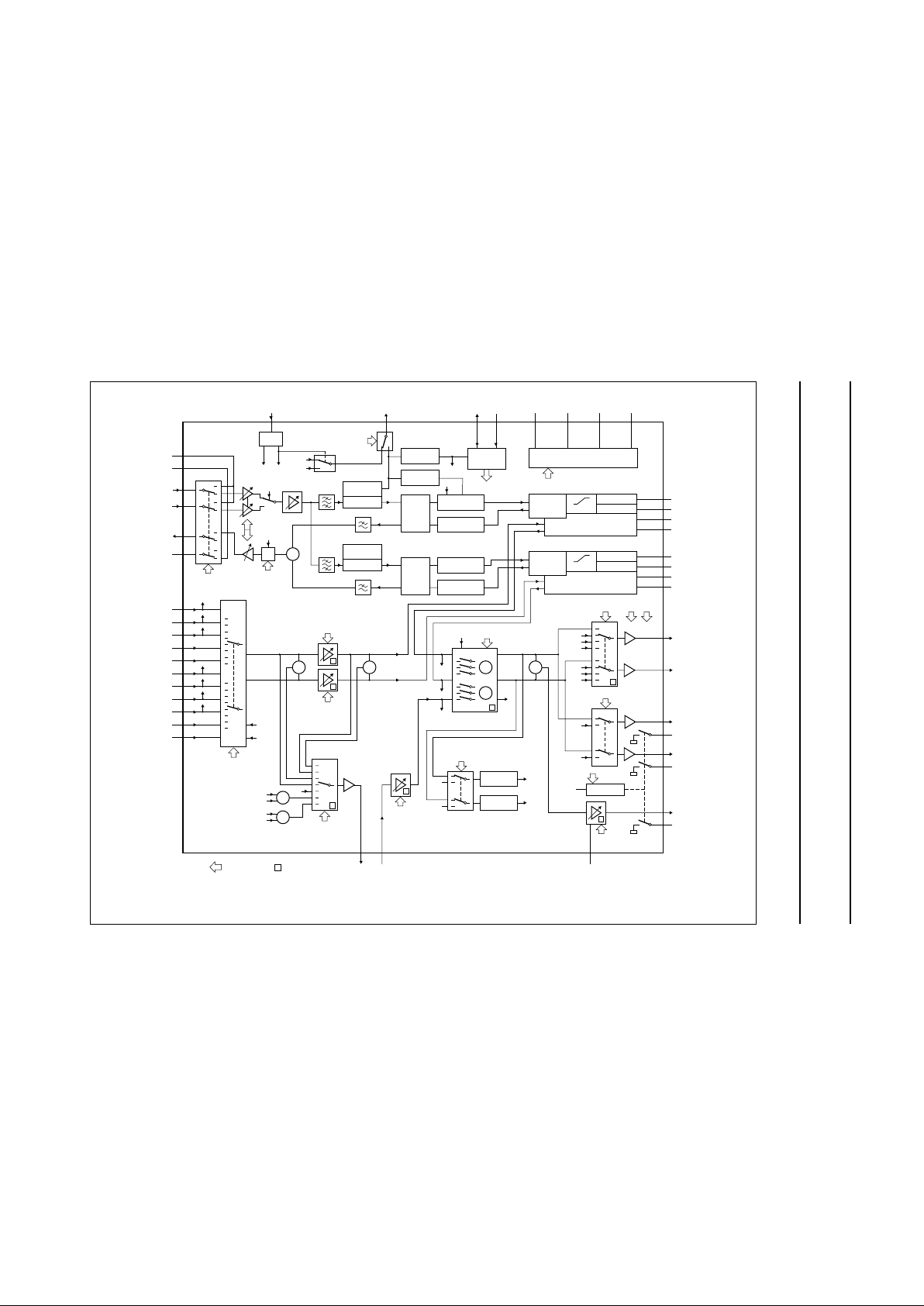
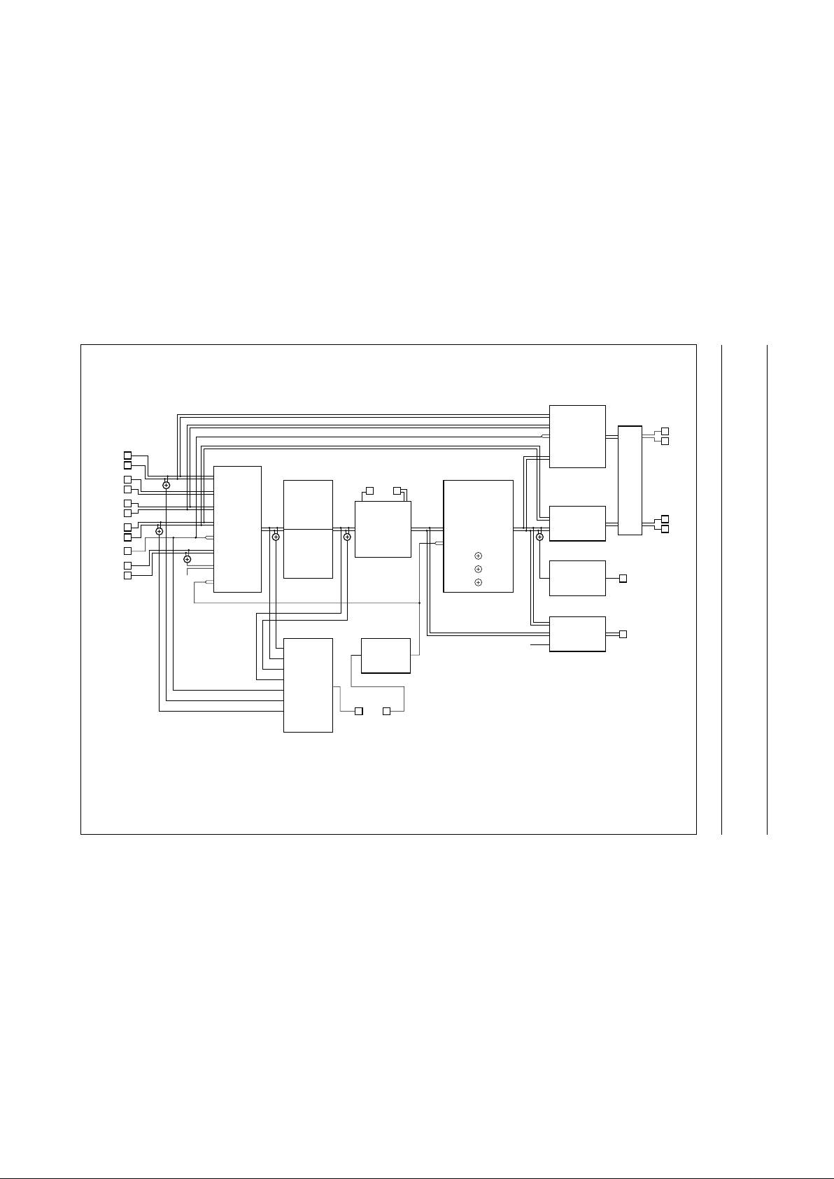
4 BLOCK DIAGRAM
n
dbook, full pagewidth
MGR834
M
M
M
M
TUL
SAP
V
CCH
GNDH
PBIN1
PBIN2
RECOUT
HMSW
1
TUNL
2
TUNR
3
CINL
4
40
39
37
35
36
38
CINR
5
EXT1L
6
EXT1R
7
EXT2L
SAP
TUL
TUR
E1L
E1R
E2L
E2R
8
EXT2R
9
AUXL
10
AUXR
N
dub
11
normal select
input select
volume right
M
normal
input
level
RF converter
mute
volume left
decoder
select
+1 dB 12 V
TDA9605H
1.7 or 1.8 MHz
SAP
21 22
LINOUT LININ
TUR
DCL
DCR
HID
HID
SDA SCL
DCFBL
26
25
EMPHL
24
DCL
23
DETL
DCFBR
EMPHR
DCR
DETR
TUL
E1L
SAP
TUR
E1R
E2L
E2R
V
CC
SAP
+
+ ++
+
+
41 44 42 43
standby select
SUPPLY
V
CC
GND
V
refIref
34 27 29 28
playback. +
record-mute,
recording
M
+
E2L
E2R
+
HF LFP
L
DCR
R
N
dub
HF LIMITER
PEAK HOLD
LEVEL
DETECTOR
PLL
CCO
(1.7 or
1.8 MHz)
LEVEL
DETECTOR
DROPOUT
CANCELING
HI-FI
DETECTOR
1.3 or 1.4 MHz
HF LFP
HF AGC
M
carrier ratio select,
record-mute
playback head
amplification,
record head
current
HF LIMITER
PLL
CCO
(1.3 or
1.4 MHz)
envelope output
select + record
envelope
output
select
+ playback
DCL
MUTEL
MUTER
LINEL
DECR
DECL
LINER
RFCOUT
MUTEC
mute
R
L
PEAK HOLD
AUTO-MUTE
line select
output selectAUTN
AUTN
M
NOISE
SUPPRESSION
NOISE
SUPPRESSION
RECTIFIER
NOISE REDUCTION
FM (DE-)MODULATOR
HEAD AMPLIFIER
I/O CONTROL
CCA
W + FM
5th ORDER
AUDIO LPF
COMPRESSOR
EXPANDER
DETECTOR
AUDIO
CLIPPER
I2C-BUS
INTERFACE
M
= mute
I2C-bus
control
HID
RM
RMHID
ENVOUT
RM
19
20
16
15
17
18
13
14
AUDIO
CLIPPER
12
RFCAGC
30
31
32
33
RECTIFIER
CCA
W + FM
5th ORDER
AUDIO LPF
COMPRESSOR
EXPANDER
DETECTOR
Fig.1 Block diagram.
1999 Apr 14 5
Philips Semiconductors Product specification
Audio processor with head amplifier for VHS hi-fi TDA9605H
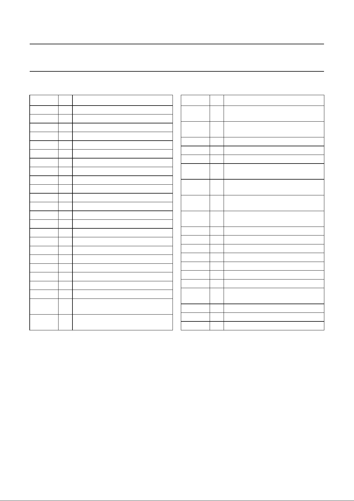
5 PINNING
SYMBOL PIN DESCRIPTION
SAP 1 tuner input mono
TUNL 2 tuner input left
TUNR 3 tuner input right
CINL 4 CINCH input left
CINR 5 CINCH input right
EXT1L 6 external 1 input left
EXT1R 7 external 1 input right
EXT2L 8 external 2 input left
EXT2R 9 external 2 input right
AUXL 10 auxiliary input left
AUXR 11 auxiliary input right
RFCAGC 12 RF converter AGC timing connection
RFCOUT 13 RF converter output
MUTEC 14 mute for RF converter output
MUTEL 15 mute for line output left
LINEL 16 line output left
LINER 17 line output right
MUTER 18 mute for line output right
DECL 19 decoder output left
DECR 20 decoder output right
LINOUT 21 linear audio output
LININ 22 linear audio input
DCFBL 23 DC feedback noise reduction
connection left
EMPHL 24 emphasis noise reduction connection
left
DCL 25 DC decoupling noise reduction
connection left
DETL 26 detector noise reduction connection
left
GND 27 ground
I
ref
28 reference standard current connection
V
ref
29 reference voltage connection
DETR 30 detector noise reduction connection
right
DCR 31 DC decoupling noise reduction
connection right
EMPHR 32 emphasis noise reduction connection
right
DCFBR 33 DC feedback noise reduction
connection right
V
CC
34 power supply
PBIN2 35 head 2 playback input
RECOUT 36 recording current output
PBIN1 37 head 1 playback input
HMSW 38 head amplifier mode switch connection
GNDH 39 ground of head amplifier
V
CCH
40 power supply of head amplifier
RMHID 41 record-mute mode or head
identification input
SDA 42 I2C-bus data input/output
SCL 43 I
2
C-bus clock input
ENVOUT 44 HF or AF envelope output
SYMBOL PIN DESCRIPTION
1999 Apr 14 6
Philips Semiconductors Product specification
Audio processor with head amplifier for VHS hi-fi TDA9605H
6 FUNCTIONAL DESCRIPTION
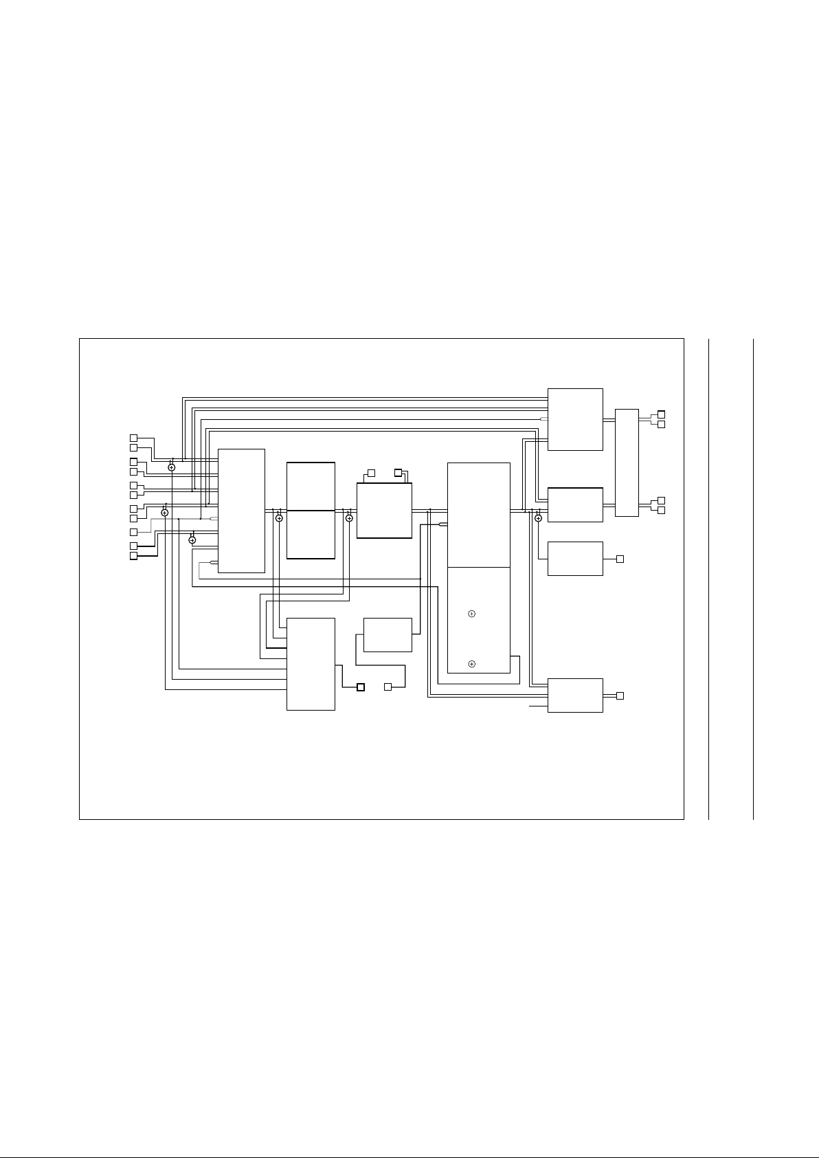
Input and output selections for the various modes are given in the following diagrams:
• Standard operating mode (see Fig.3)
• Dub-mix mode (see Fig.4)
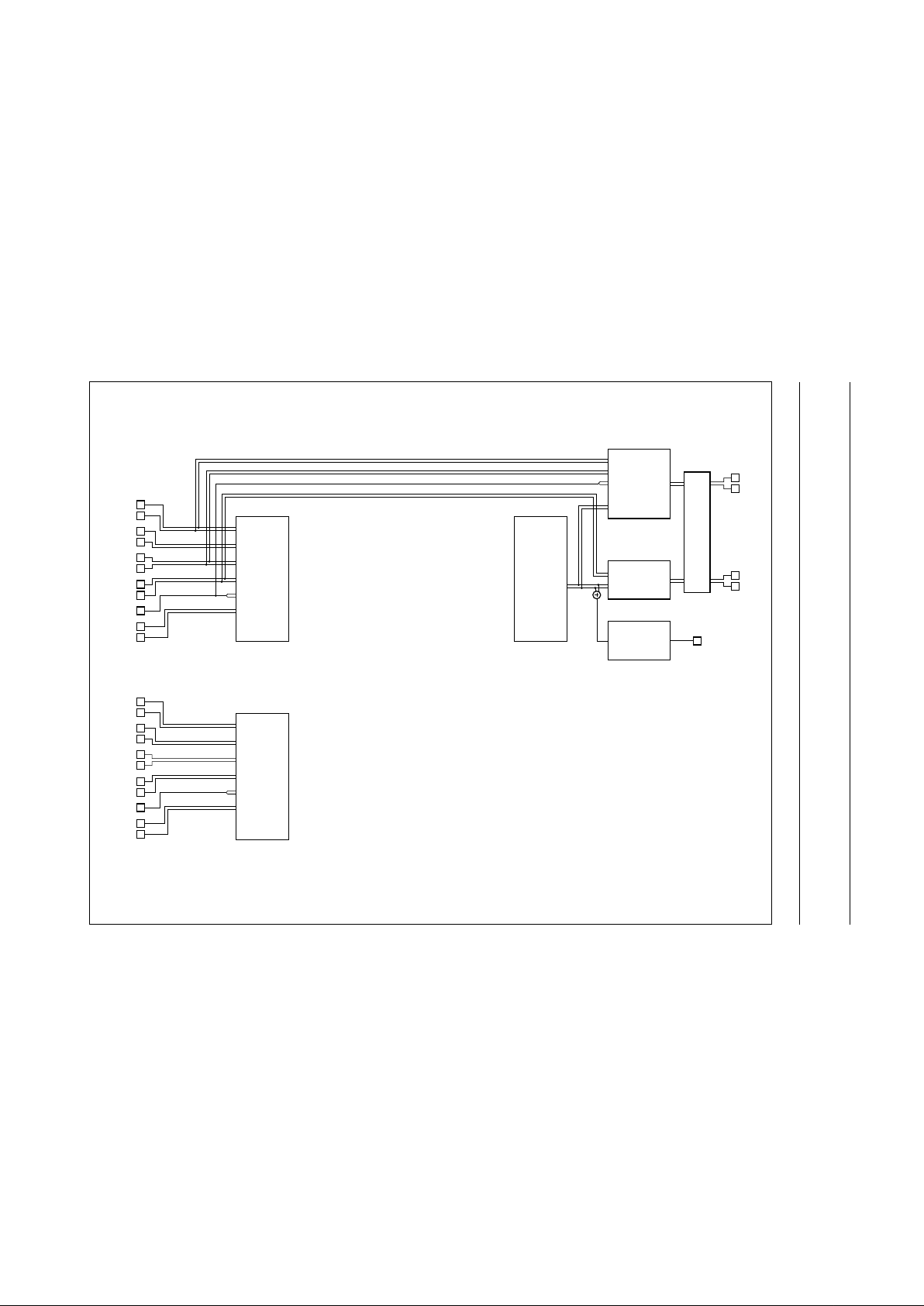
• Standby mode: active or passive (see Fig.5).
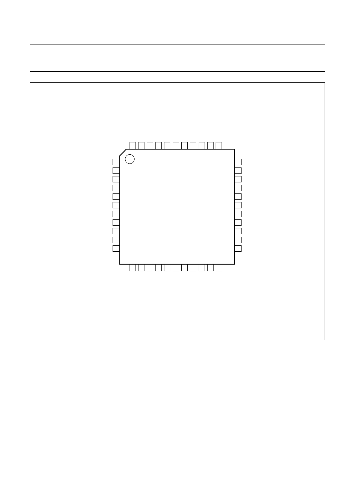
Fig.2 Pin configuration.
handbook, full pagewidth
1
2
3
4
5
6
7
8
9
10
11
33
32
31
30
29
28
27
26
25
24
23
12
13
14
15
16
17
18
19
20
21
22
44
43
42
41
403938
37
36
35
34
TDA9605H
MGR835
DCFBR
EMPHR
DCR
DETR
I
ref
GND
DETL
DCL
EMPHL
DCFBL
SAP
TUNL
TUNR
CINL
CINR
EXT1L
EXT2L
EXT2R
AUXR
V
ref
SCL
SDA
RMHID
V
CCH
GNDH
HMSW
RECOUT
PBIN2
V
CC
ENVOUT
PBIN1
RFCOUT
MUTEC
MUTEL
LINEL
LINER
MUTER
DECR
LINOUT
LININ
RFCAGC
DECL
EXT1R
AUXL
1999 Apr 14 7
Philips Semiconductors Product specification
Audio processor with head amplifier for VHS hi-fi TDA9605H
This text is here in white to force landscape pages to be rotated correctly when browsing through the pdf in the Acrobat reader.This text is here in
_white to force landscape pages to be rotated correctly when browsing through the pdf in the Acrobat reader.This text is here inThis text is here in
white to force landscape pages to be rotated correctly when browsing through the pdf in the Acrobat reader. white to force landscape pages to be ...
o
ok, full pagewidth
MGR836
TUNL
TUNER
MUTE
(−47 to 0 dB;
0 to +15 dB)
MUTE
(0 to +14 dB)
AUDIO FM
PROCESSING
HI-FI
MUTE
(−47 to 0 dB;
0 to +15 dB)
CINCH
EXT1
EXT2
SAP
(1)
AUX
INPUT SELECT
INPUT LEFT
VOLUME
VOLUME LEFT
SAP
LINOUT
linear audio
processing
LININ
TUNER
EXT2
MUTE
DUB MIX
MUTE
LEFT
EXT2
OUTPUT SELECT
OUTPUT SELECT
ENVOUT
RFCOUT
HF ENVELOPEHF envelope
STEREO
RIGHT
STEREO
NORMAL
TUNER
EXT1
SAP
MUTE
OUTPUT SELECT
NORMAL
TUNR
CINL
CINR
EXT1L
EXT1R
EXT2R
AUXL
SAP
EXT2L
AUXR
volume left
volume right
output select
line select
input select
NORMAL LEFT
NORMAL RIGHT
NORMAL STEREO
decoder select
0 dB AGC
0 dB
+1 dB
MUTE
RF converter AGC
envelope select
normal input levelnormal select
DECL
line output
amplification
DECR
LINEL
LINER
RECOUT
tape
PBIN1
PBIN2
Fig.3 Input and output selections for standard operating mode.
(1) For dub-mix mode signal selections see Fig.4.
1999 Apr 14 8
Philips Semiconductors Product specification
Audio processor with head amplifier for VHS hi-fi TDA9605H
This text is here in white to force landscape pages to be rotated correctly when browsing through the pdf in the Acrobat reader.This text is here in
_white to force landscape pages to be rotated correctly when browsing through the pdf in the Acrobat reader.This text is here inThis text is here in
white to force landscape pages to be rotated correctly when browsing through the pdf in the Acrobat reader. white to force landscape pages to be ...
k
, full pagewidth
MGR837
TUNL
MUTE
(−47 to 0 dB;
0 to +15 dB)
MUTE
(0 to +14 dB)
AUDIO FM
PROCESSING
HI-FI
MUTE
(−47 to 0 dB;
0 to +15 dB)
INPUT SELECT
INPUT LEFT
VOLUME
VOLUME LEFT
SAP
LINOUT
linear audio
processing
(record)
LININ
TUNER
EXT2
MUTE
DUB MIX
MUTE
LEFT
EXT2
OUTPUT SELECT
OUTPUT SELECT
ENVOUT
RFCOUT
HF ENVELOPEHF envelope
STEREO
RIGHT
STEREO
NORMAL
TUNER
EXT1
SAP
MUTE
OUTPUT SELECT
TUNR
CINL
CINR
EXT1L
EXT1R
EXT2R
AUXL
SAP
EXT2L
AUXR
RECOUT
tape
volume aux output select
line select
input select
PBIN1
PBIN2
NORMAL
NORMAL
NORMAL
MUTE
LEFT
RIGHT
MUTE
LEFT
RIGHT
LEFT RIGHT
LEFT RIGHT
decoder select
0 dB AGC
0 dB
+1 dB
MUTE
RF converter AGC
envelope select
normal input levelnormal select
DECL
line output
amplification
DECR
LINEL
LINER
volume hi-fi
(playback)
Fig.4 Input and output selections for dub-mix mode.
Dub-mix mode: IS2 = 1, IS1 = 0 and IS0 = 1.
Input mixing of the hi-fi (playback) signal with the auxiliary, used for linear audio dubbing recording.
Selections generally used in combination with dub-mix mode are shown in heavy line type.
1999 Apr 14 9
Philips Semiconductors Product specification
Audio processor with head amplifier for VHS hi-fi TDA9605H
This text is here in white to force landscape pages to be rotated correctly when browsing through the pdf in the Acrobat reader.This text is here in
_white to force landscape pages to be rotated correctly when browsing through the pdf in the Acrobat reader.This text is here inThis text is here in
white to force landscape pages to be rotated correctly when browsing through the pdf in the Acrobat reader. white to force landscape pages to be ...
handbook, full pagewidth
MGR838
TUNL
MUTE
EXT2
OUTPUT SELECT
RFCOUT
TUNER
EXT1
SAP
MUTE
OUTPUT SELECT
TUNR
CINL
CINR
EXT1L
EXT1R
EXT2R
AUXL
SAP
EXT2L
AUXR
line select
input select
MUTE
output select
TUNL
MUTE
TUNR
CINL
CINR
EXT1L
EXT1R
EXT2R
AUXL
SAP
EXT2L
AUXR
input select
decoder select
0 dB
+1 dB
MUTE
RF converter AGC
DECL
line output
amplification
DECR
LINEL
LINER
Fig.5 Input and output selections for standby modes.
b. Passive standby mode (bit STBP = 1); over 90% power reduction.
a. Active standby mode (bit STBA = 1, bit STBP = 0); over 80% power reduction.

1999 Apr 14 10
Philips Semiconductors Product specification
Audio processor with head amplifier for VHS hi-fi TDA9605H
6.1 Record-mute mode or head identification
selection
Pin RMHID allows input of two independent digital control
signals for selecting the record-mute or head identification
modes which are voltage coded. The RM control signal is
selected via a 10 kΩ resistor and the HID control signal is
selected via a 18 kΩ resistor. This set-up enables the two
signals within the TDA9605H to be separated. The RM
control signal is only in use during the record mode
(bit AFM = 1); during the playback mode (bit AFM = 0) the
RM signal is ignored. Pin RMHID should be connected to
ground when the RM control signal is not used.
The use of the RM control signal is optional since the same
function is available via the I
2
C-bus control in the
record-mute mode. However, accurate timing of recording
start and stop may sometimes be difficult to realize via the
I2C-bus control. In this event the RM control signal can be
used instead. There is also the possibility to use the
record-mute mode control line of the video head amplifier.
6.2 Hi-fi audio output level
When the application circuit is used in accordance with the
application diagram, the standard FM deviation of 50 kHz
equals a 1 kHz audio signal of −8 dBV line output level
(bit LOH = 0). A different standard audio level can be
selected by changing the external filter components of the
noise reduction on pins EMPHL and EMPHR
(see Section 14.3). The standard audio level changes
proportionally to the impedance of the external
de-emphasis filter.
6.3 Reference current
The external resistor connected to pin I
ref
defines the
internal reference currents and determines the
temperature stability of circuits adjusted by the
auto-calibration function.
6.4 Head amplifier
6.4.1 PLAYBACK MODE
The playback mode is selected by setting bit AFM = 0.
During the playback mode the input circuit on pins PBIN2
and PBIN1 is enabled (see Fig.6). Pin RECOUT is
disabled and pin HMSW shows a low impedance to
ground, so realizing an AC ground for the head circuit via
the external capacitor connected between these pins.
The head identification (HID) signal on pin RMHID selects
between the head signals on pins PBIN2 or PBIN1. Head
selection is defined as shown in Table 1.
The state of the RM control signal on pin RMHID is don’t
care in the playback mode.
I
2
C-bus control bits HAC2, HAC1 and HAC0 offer a wide
selection of playback amplification to fit different head and
head transformer specifications. The advised setting of the
playback amplification realizes a level of 24 mV (RMS) for
each carrier signal after the head amplifier to obtain a
17 dB overhead compared to the auto-normal level (hi-fi
detection). However, performance is not critical and a
different setting can be used if desired.
The carrier level can be measured using the HF envelope
output voltage on pin ENVOUT (bit EOS = 1). During
standard operating mode the HF envelope signal is
derived from the left channel carrier amplitude
(1.3 or 1.4 MHz carrier) but the special test 10 of the test
mode also enables the HF envelope output of the right
channel carrier amplitude (1.7 or 1.8 MHz carrier).
The advised carrier playback level of 24 mV (RMS) equals
an HF envelope voltage of 3.3 V.
The head amplifier output signal can be monitored directly
by using test 8 of the test mode. Pin ENVOUT functions as
the test output showing 6 dB attenuation compared to the
actual head amplifier output level (see Section 14.4).
Table 1 Selection of the head signal
6.4.2 R
ECORD-MUTE MODE
The record-mute mode is selected by setting bit AFM = 1
and either setting bits DOC, SHH and DETH to logic 0 or
switching the RM control signal to HIGH-level.
During the record-mute mode no recording current is
present on pin RECOUT (see Fig.6). The head amplifier
status actually equals the playback mode, however, the
second amplifier stage is disabled to minimize power
consumption.
The RM control signal on pin RMHID enables fast
switching between the record and record-mute modes
(see Table 2). If the I2C-bus control is set to the record
mode, the use of record-mute mode control via pin RM
allows for accurate timing of recording start and stop,
independent of the I2C-bus control (see Section 6.1).
HID
SIGNAL
LEVEL ON PIN RMHID
SELECTION OF
HEAD SIGNAL
LOW lower than 0.6 V or
between 2.65 and 3.8 V
pin PBIN2
(head 2)
HIGH between 1.0 and 2.35 V
or higher than 4.3 V
pin PBIN1
(head 1)
1999 Apr 14 11
Philips Semiconductors Product specification
Audio processor with head amplifier for VHS hi-fi TDA9605H
Table 2 Selection of recording modes
6.4.3 R
ECORD MODE
The record mode is selected by setting bit AFM = 1 and
setting bits DOC, SHH and DETH from logic 001 to 111
and switching the RM control signal to LOW-level.
During the record mode actual recording is activated and
the recording current is output on pin RECOUT
(see Fig.6). Pins PBIN2 and PBIN1 form a connection to
the 5 V head amplifier supply voltage (V
CCH
). Pin HMSW
is internally connected to pin RECOUT and the external
capacitor has no function in this mode.
The desired carrier mix ratio is set via I2C-bus control
bits DOC, SHH and DETH. A wide selection of recording
currents is available to fit different head and head
transformer specifications and are set via bits HAC2,
HAC1, HAC0 and range bit HRL. The setting of the carrier
mix ratio does not change the selected recording current.
RM
SIGNAL
LEVEL ON
PIN RMHID
RECORD MODE
LOW lower than 2.35 V record or record-mute
mode as defined by
I
2
C-bus control
HIGH higher than 2.65 V record-mute mode
The DC bias current on pin RECOUT is changed
proportional to the selected recording current for
optimizing the performance and minimizing the power
consumption for each recording current selected.
A Boucherot damping circuit is connected between
pin HMSW and ground to prevent head current resonance
peaking. A capacitor of 10 nF and a resistor of 470 Ω are
specified in Fig.14, but the component values are not
critical.
6.4.4 H
EAD AMPLIFIER POWER SUPPLY AND GROUND
The head amplifier is supplied via a separate 5 V supply
(pin V
CCH
) and ground (pin GNDH).
A capacitor of 100 nF should be placed close to the device
between pins V
CCH
and GNDH for proper decoupling of
the power supply.
The head amplifier ground (pin GNDH) should be
connected to the main ground (pin GND).
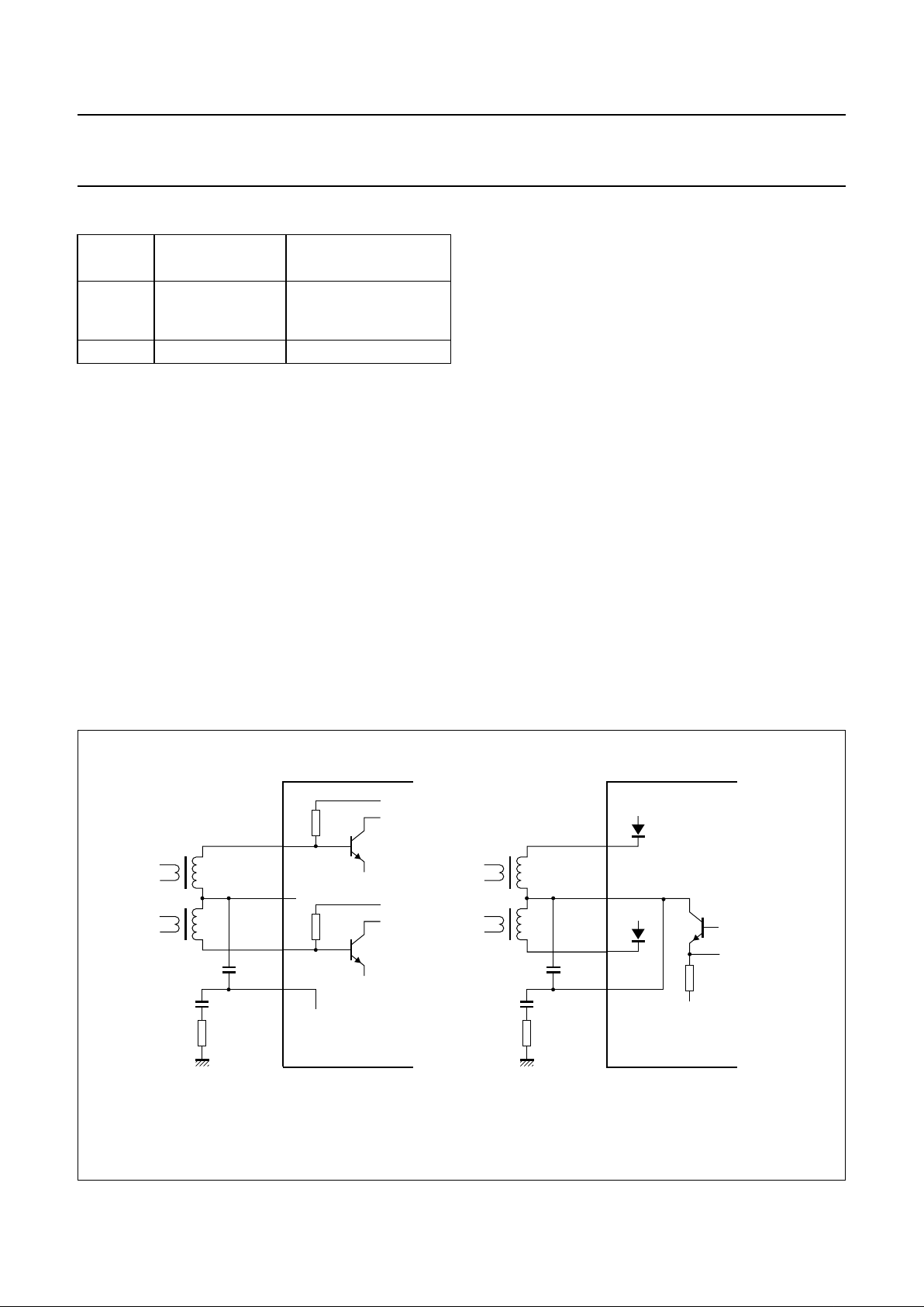
Fig.6 Simplified circuit diagrams of the head amplifier modes.
handbook, full pagewidth
MGR841
35 kΩ
GNDH
GNDH
AH2
PBIN2
PBIN1
HMSW
RECOUT
AH1
35 kΩ
GNDH
TDA9605H
38
37
36
35
PBIN2
PBIN1
HMSW
RECOUT
38
37
36
35
5 Ω
GNDH
AH2
AH1
V
CCH
V
CCH
TDA9605H
a. Playback mode and record-mute mode. b. Record mode.
1999 Apr 14 12
Philips Semiconductors Product specification
Audio processor with head amplifier for VHS hi-fi TDA9605H
6.5 Automatic calibration
The integrated auto-calibration system is activated by
means of bit CALS of the power byte (see Fig.7).
The auto-calibration system ensures hi-fi processing is
well in accordance with the VHS hi-fi system standard by
an automated adjustment of carrier frequencies,
band-pass filters and noise reduction filters. Calibration is
only needed after start-up of the video recorder.
The calibration settings remain stable as long as the
supply voltage (VCC) is present.
Auto-calibration is only executed in the record-mute mode
or record mode and no standby mode or test mode should
be selected, i.e. auto-calibration requires the setting of
bit AFM = 1, bit STBP = 0, bit STBA = 0 and bit TEST = 0.
Auto-calibration is started after setting bit CALS = 1.
Calibration is performed fully automatically, using the HID
control signal as a time reference. Audio signals are not
disturbed during the calibration process.
Calibration of the oscillator frequencies is performed by
measuring the number of oscillator cycles within one
period when the HID control signal is at HIGH-level and
comparing this result with an internal value stored in the
Read Only Memory (ROM). Four different ROM values are
available for NTSC or PAL (SECAM) system calibration of
both the left and right channel carrier.
In case of NTSC a special routine is active for the
calibration of the right channel carrier which results in a
frequency difference between the left and right channel
carrier near to 401.2 kHz. This value effectively reduces
the crosstalk from hi-fi carriers to video colour signal as
present during Extended Play (EP) tape speed. NTSC
calibration uses a standard HID control signal of 29.97 Hz
(pulse width =16.683 ms) where PAL calibration uses a
standard HID control signal of 25 Hz (pulse
width = 20 ms). After auto-calibration the maximum
frequency error is ±5 kHz assuming a time error of
maximum of 5 µs when the HID control signal is at
HIGH-level. Jitter on the HID control signal should not
exceed 1 µs to realize EP optimization within ±2 kHz for
NTSC. In general, the crystal based HID control signal
available in the video recorder can be used without
modification.
When the calibration of the oscillators is completed the
band-pass filters are calibrated. The integrated weighting
and FM de-emphasis filters of the noise reduction are
calibrated at the same time.
The total auto-calibration time needed is maximum
17 cycles of the HID control signal. Completion of the
calibration is signalled by bit CALR =1 of the read byte.
The calibration can also be monitored by means of the
envelope output. For this purpose the voltage on
pin ENVOUT is forced to >2.5 V during the calibration.
The audio signal to the audio envelope function (level
meter) should be muted (i.e. output select = mute).
Fig.7 Example of automatic calibration flow.
handbook, full pagewidth
MGR842
logic 1
logic 0
logic 1
logic 0
4 V3 V
5 V
calibration
ready
I
2
C-bus write bit CALS
I
2
C-bus read bit CALR
ENVOUT output
RMHD input
left channel oscillator
right channel oscillator
band-pass and
noise reduction filters
1999 Apr 14 13
Philips Semiconductors Product specification
Audio processor with head amplifier for VHS hi-fi TDA9605H
Otherwise, the audio envelope output voltage may
become >2.5 V which makes it impossible to detect the
completion of the calibration on pin ENVOUT.
Calibration relies upon the frequency accuracy of the HID
control signal. The calibration result may be incorrect
when the HID control signal is disturbed during a critical
part of the calibration. An additional check is incorporated
to detect such a situation by reading bit CALE during
calibration. When bit CALE = 1, the calibration result is
detected to be unreliable due to external causes. A new
auto-calibration can be started by setting bit CALS = 0
followed by setting bit CALS = 1. Bit CALE always reads
logic 1 when bit CALS is logic 0.
The oscillators and band-pass filters can be switched
between NTSC and PAL system frequencies after a
calibration in NTSC or PAL mode without the need of
additional calibration. Switching between these system
modes is executed immediately and can be done in any
operating mode. The frequency accuracy of system
switching is 100 ±3 kHz for both carriers. To obtain the
best possible frequency accuracy in the record mode it is
good practice to recalibrate after system switching.
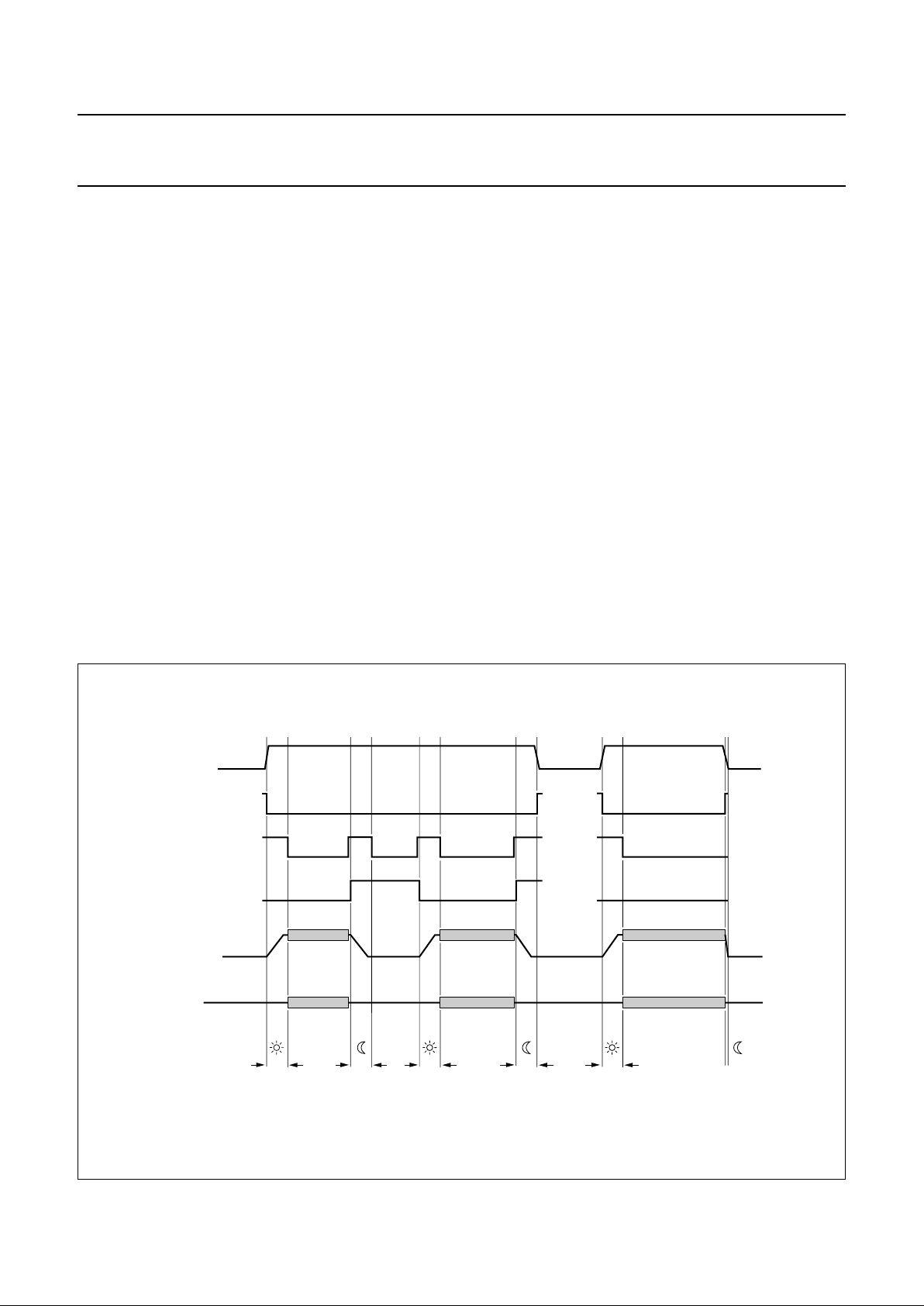
6.6 Power muting
Switching off and on of the power supply voltage or using
the built-in passive standby mode results in rising and
dropping of the output DC voltages and causes strong
disturbances on the output pins. The TDA9605H includes
three integrated mute switches to block such disturbances
so avoiding the need for an external mute circuit. Pop-free
line and RF converter output signals are realized by
connecting the integrated power mute switches behind the
line and RFC output capacitors.
Power muting is active when bit MUTE = 1 (see Fig.8).
Power muting is automatically activated when V
CC
is
switched on, because this situation is the Power-on reset
default state. The integrated mute switches on
pins MUTEC, MUTEL and MUTER are closed and form a
low-impedance path to ground. Furthermore, the
pins RFCOUT, LINEL and LINER are current limited to
−1 mA to avoid excessive supply currents and to achieve
good noise attenuation without the need for a series
resistor between the output and mute pins. Pins DECL and
DECR are also current limited for using the integrated
power mute switches or for assisting external muting.
Fig.8 Examples of power mute control and the auto-mute function.
handbook, full pagewidth
MGR843
V
CC
auto-mute
(V
CC
< 7 V)
bit MUTE (I
2
C-bus)
(
1)
(
1)
bit STBP (I
2
C-bus)
MUTEC
MUTEL
MUTER
RFCOUT
LINEL
LINER
output signal
with power mute
t
mute
t
mute
t
mute
t
mute
t
mute
auto-mute
active
operation
power
off
power
off
active
operation
power off
(standby)
active
operation
passive
standby
(1) Power-on reset.

1999 Apr 14 14
Philips Semiconductors Product specification
Audio processor with head amplifier for VHS hi-fi TDA9605H
During power muting the internal output signal is also
muted. After the output DC voltage has been established
power muting can be de-activated by setting bit MUTE = 0.
Now the mute switches are opened resulting in a
high-impedance path of 100 kΩ to ground. The output
current limiting is not active.
Power muting is also used in combination with the
integrated passive standby mode (bit STBP = 1). During
this mode the output circuits are switched off and the line,
decoder and RF converter output voltages decrease to 0 V
using a discharge current of 1 mA. Do not set power mute
mode and change the passive standby mode at the same
time. Power mute mode should be activated first, followed
by switching on or off of the passive standby mode to avoid
possible output glitches.
It should be noted that the time needed for stabilizing the
output DC voltage is proportional to the output capacitor
value. A safe mute time is 200 ms using a 10 µF capacitor
(t
mute
=C×20000 s). Power muting consumes
approximately 4 mA additional supply current, so to obtain
minimum power consumption the mute mode should be
de-activated after use. Very good performance is achieved
for power-up, power-down and passive standby mode
switching.
An auto-mute function is included which activates power
muting when the supply voltage drops below 7 V.
The performance of this auto-mute function depends upon
the power voltage drop rate. The voltage drop rate should
not exceed 1 V during 10 ms. The best performance
independent of voltage drop rate is realized by activating
the passive standby mode before switching off the power
supply voltage (by setting bit MUTE = 1 and bit STBP = 1).
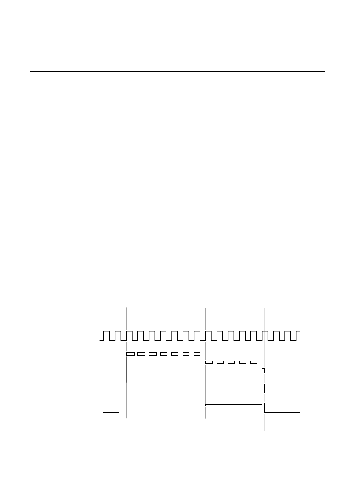
6.7 Envelope output
Pin ENVOUT is an analog output for stereo audio level
(e.g. level meter display) and for playback FM carrier level
(e.g. auto-tracking). The functional diagram is given in
Fig.9 and the timing diagram is shown in Fig.10. Only one
ADC input is needed on the microcontroller for reading all
the required information.
During the playback mode the selection between audio
level and carrier level information is realized by setting
I
2
C-bus control bit EOS (see Table 3). The AF envelope
output is defined by the signal selection made at the output
select.
During the record mode bit EOS offers the selection
between the audio level of the output select or the audio
level of the fixed hi-fi stereo signal. This is a helpful setting
when the microcontroller uses the audio level information
to adjust the hi-fi recording level (volume control).
The HF envelope output signal is continuous and is
derived from the left channel carrier. The HF envelope
output exhibits a logarithmic characteristic (see Fig.11).
In a standard application circuit only the left channel carrier
level is required to support auto-tracking or manual
tracking. However, test 10 of the special test mode allows
for the right channel carrier level output instead for
measurement purposes (see Section 14.4).
The AF envelope output as a function of the output level is
given in Fig.12.
The AF envelope circuit uses time multiplexing for the left
and right channel audio level. A peak-hold function and
dynamic range compression (square root function) are
included for easy read out. The peak-hold function and the
left and right channel multiplexing are controlled by the
HID control signal on pin RMHID (see Table 4).
Table 3 Selection of the envelope output
Table 4 AF envelope output with channel multiplexing
MODE BIT AFM BIT EOS ENVELOPE OUTPUT FUNCTION
Playback
0
0 AF envelope: via output select level meter display
1 HF envelope auto-tracking or manual tracking display
Record
1
0 AF envelope: via output select level meter display
1 AF envelope: hi-fi stereo record volume control (and level display)
HID SIGNAL LEVEL ON PIN RMHID AF ENVELOPE OUTPUT
LOW lower than 0.6 V or between 2.65 and 3.8 V left channel audio peak level
HIGH between 1.0 and 2.35 V or higher than 4.3 V right channel audio peak level
1999 Apr 14 15
Philips Semiconductors Product specification
Audio processor with head amplifier for VHS hi-fi TDA9605H
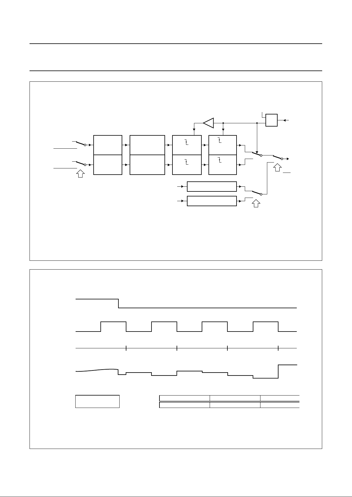
Fig.9 Functional diagram of the envelope output circuit.
handbook, full pagewidth
MGR845
output select
hi-fi
output select
left channel audio:
right channel audio:
hi-fi
EOS • AFM
AF
envelope
FULL-WAVE
RECTIFIER
FULL-WAVE
RECTIFIER
PEAK HOLD
PEAK HOLD
1.3 or 1.4 MHz carrier
RESET
RESET
EOS • AFM
test
10
HF
envelope
SAMPLE-
AND-HOLD
RMHID
RM
HID
ENVOUT
SAMPLE-
AND-HOLD
SAMPLE
SAMPLE
HF LEVEL DETECTOR
1.7 or 1.8 MHz carrier
HF LEVEL DETECTOR
SQUARE ROOT
COMPRESSION
SQUARE ROOT
COMPRESSION
t
d
Fig.10 Timing diagram of the envelope output signal.
handbook, full pagewidth
MGR844
I2C-bus
registers
HID signal
HID period
ENVOUT
level meter
display
EOS = 0 or AFM = 1
EOS = 1 and
AFM = 0
0123
HF envelope
peak right
in period −1
peak right
in period 0
peak right
in period +1
peak right
in period +2
peak left
in period 0
left (period 0)
right (period 0)
tracking level
indication
peak left
in period 1
peak left
in period 2
peak left
in period +3
left (period 1)
right (period 1)
left (period 2)
right (period 2)
1999 Apr 14 16
Philips Semiconductors Product specification
Audio processor with head amplifier for VHS hi-fi TDA9605H
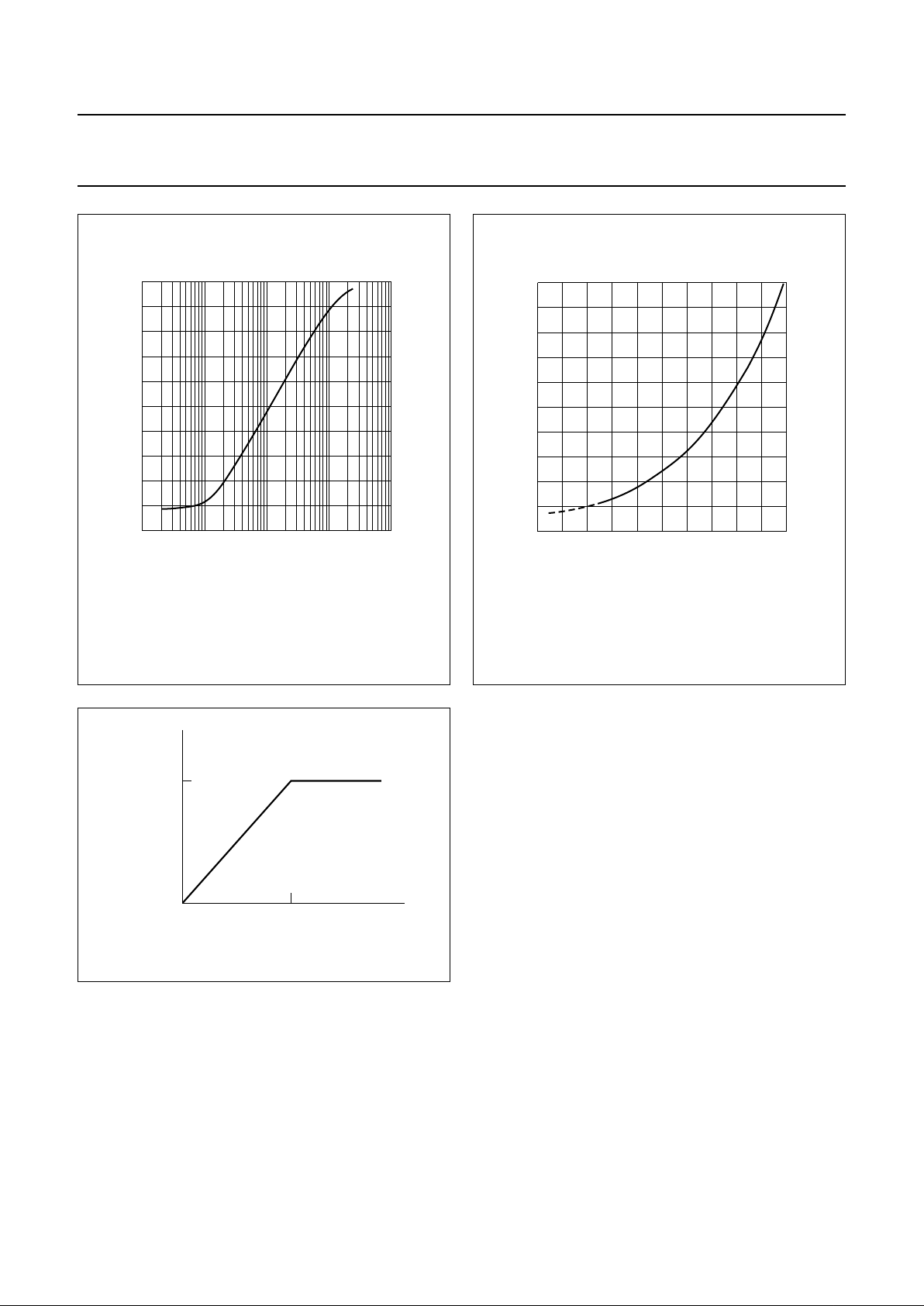
Fig.11 HF envelope output (playback carrier level).
1.3 MHz (NTSC) or 1.4 MHz (PAL) at internal node between head
amplifier and HF AGC.
handbook, halfpage
0
5
1
2
3
4
MGR846
10
−1
11010
2103
ENVOUT
output
voltage
(V)
left channel carrier amplitude (RMS value) (mV)
Fig.12 AF envelope output (audio peak level).
Bit LOH = 0.
handbook, halfpage
5
0
1
MGR847
2
3
4
−40 10−30 −20 −10 0
ENVOUT
output
voltage
(V)
LINEL and LINER output level (dBV)
Fig.13 AGC output of RF converter.
handbook, halfpage
MGR848
RF
converter
output
(dBV)
−3
−3
line output (dBV)
6.8 RF converter output
An AGC function is incorporated to avoid overmodulation
in the RF converter connected to pin RFCOUT. The AGC
limits the maximum signal level on the RF converter output
to −3 dBV (see Fig.13).
The RF converter output can be muted by setting
bit RFCM = 1. When using this RF converter mute, the
AGC control is reset by discharging the capacitor
connected to pin RFACG.
 Loading...