

Philips TDA9302 Service Manual
VERTICALDEFLECTION OUTPUTCIRCUIT
.
POWERAMPLIFIER
.
FLYBACKGENERATOR
.
THERMAL PROTECTION
DESCRIPTION
The TDA9302Hisa monolithicintegratedcircuitin
HEPTAWATT
power boosterfordirect driving of verticalwindings
of TV yokes. It is intendedforuse in Color and B &
W television as well as in monitorsand displays.
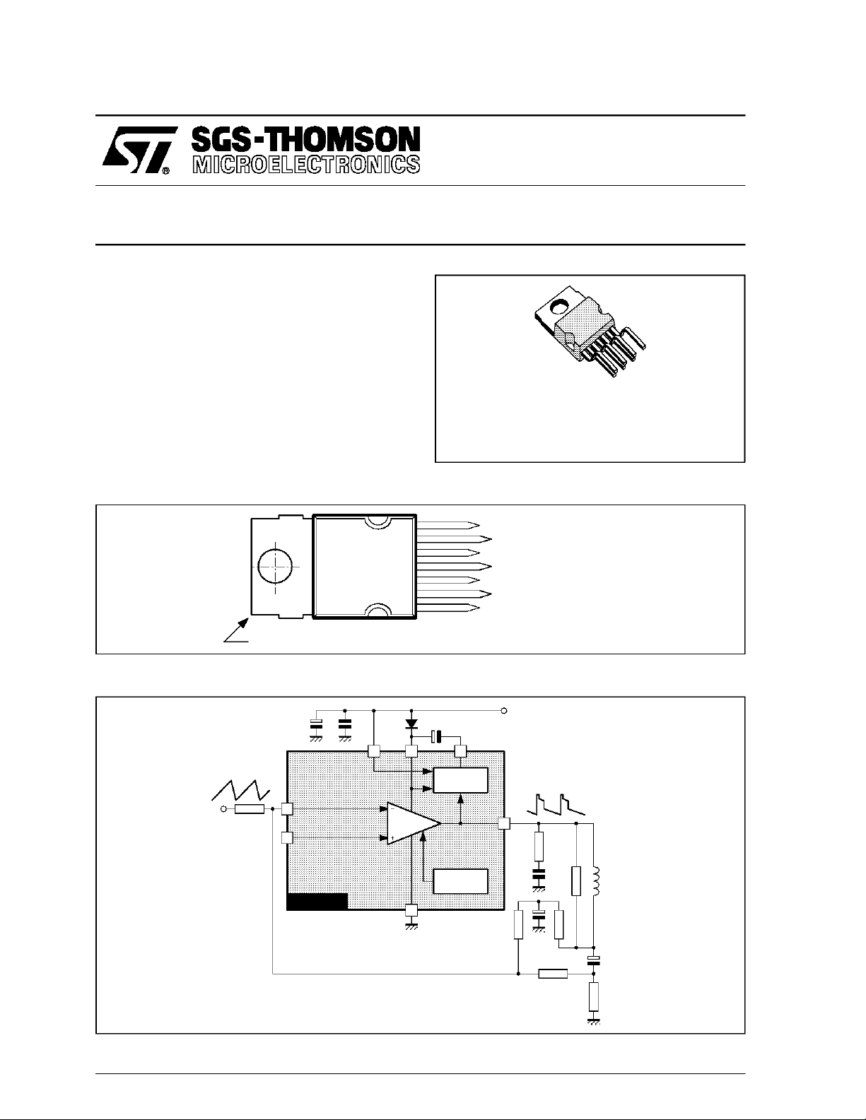
PIN CONNECTIONS(top view)
TM
package. It is a high efficiency
TDA9302H
HEPTAWATT
(Plastic Package)
ORDER CODE : TDA9302H
BLOCK DIAGRAM
Tab connectedto Pin4
1
7
TDA9302H
7
6
5
4
3
2
1
Power
Amplifier
NON-INVERTING INPUT
OUTPUT STAGESUPPLY
OUTPUT
GROUND
FLYBACK GENERATOR
SUPPLY VOLTAGE
INVERTING INPUT
9302H-01.EPS
+V
S
362
Flyback
Generator
5
Thermal
Protection
4
YOKE
August 1992
9302H-02.EPS
1/5
TDA9302H
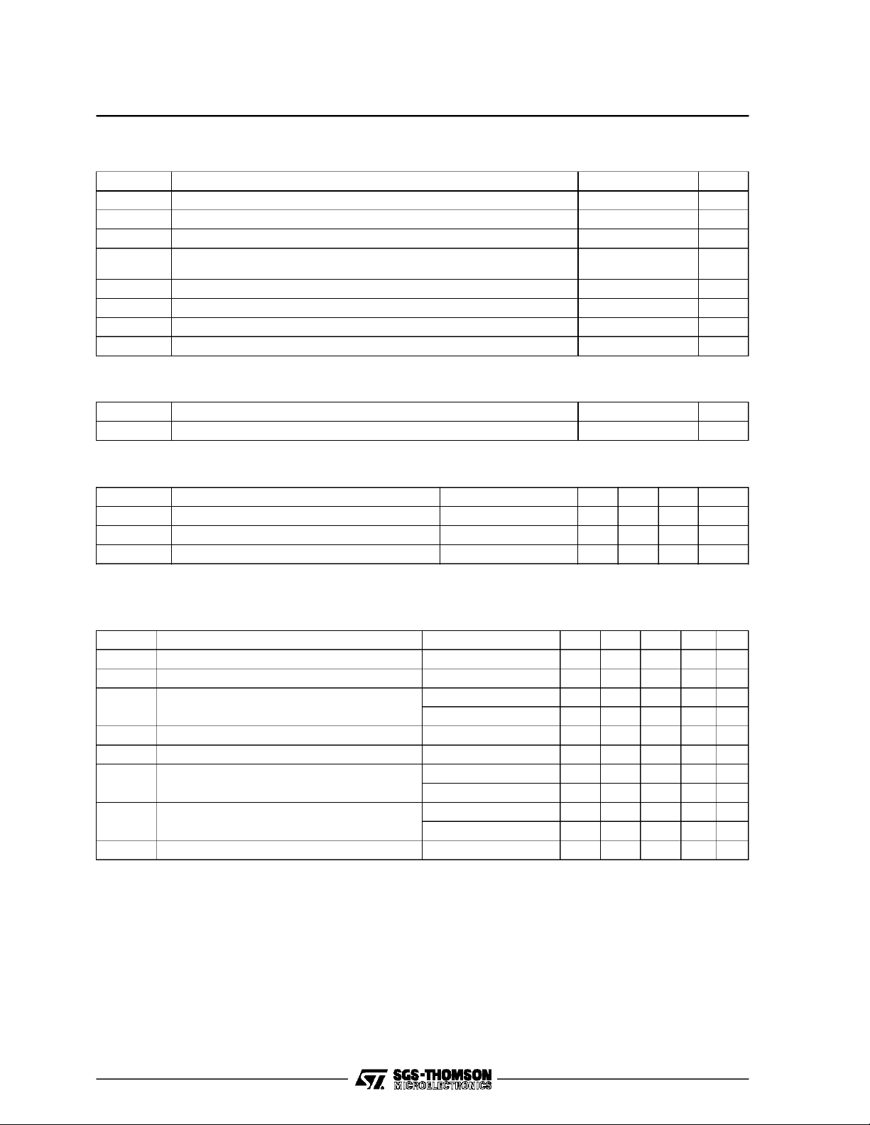
ABSOLUTEMAXIMUM RATINGS AT TA=25oC
Symbol Parameter Value Unit
V
S
V
5,V6
V
3
V1,V7Amplifier Input Voltage + V
I
o
I
3
P
tot
T
stg,Tj
THERMALDATA
Symbol Parameter Value Unit
R
th (j–c)
RECOMMENDED OPERATING CHARACTERISTICS AT TA=25oC
Symbol Parameter Test Conditions Min. Typ. Max. Unit
V
2M
V
2R
I
5PP
Supply Voltage (pin 2) 35 V
Flyback Peak Voltage 60 V
Voltage at Pin 3 + V
– 0.5
s
s
Deflection Output Current ± 1.8 A
Pin 3 DC Current at V5<V
Total Power Dissipation at T
2
=90°C15W
case
100 mA
Storage and Junction Temperature – 40, +150 °C
Thermal Resistance Junction-case Max. 4 °C/W
Recommended Supply Voltage 25 V
Operating Supply Voltage Range 15 30 V
Deflection Output Current 2 App
V
9302H-01.TBL
9302H-02.TBL
9302H-03.TBL
ELECTRICAL CHARACTERISTICS
(refer to the testcircuits, V
=35V, T
S
Symbol Parameter Test Conditions Min. Typ. Max. Unit Fig.
Pin 2 Quiescent Current I3=0,I5= 0 16 mA 1a
I
2
Pin 6 Quiescent Current I3=0,I5= 0 36 mA 1a
I
6
Amplifier Input Bias Current V1= 1 V, V7= 2 V – 0.1 – 1 µA1a
I
1
V
V
V
V
Pin 3 Saturation Voltage to GND I3= 20 mA 1 1.5 V 1c
3L
Quiescent Output Voltage Vs= 35V, Ra=39kΩ 18 V 1d
5
Output Saturation Voltage to GND I5= 1 A 0.9 1.3 V 1c
5L
Output Saturation Voltage to Supply – I5= 1 A 1.5 2 V 1b
5H
Junction Temperature for Thermal Shut Down 140 °C
T
j
=25oC unlessotherwisespecified)
amb
= 2 V, V7= 1 V – 0.1 – 1 µA1a
V
1
= 0.7 A 0.7 1 V 1c
I
5
= 0.7 A 1.3 1.8 V 1b
–I
5
9302H-04.TBL
2/5
 Loading...