


Product specification
Supersedes data of 1996 Jun 28
File under Integrated Circuits, IC02
1997 Dec 01
INTEGRATED CIRCUITS
TDA9177
YUV transient improvement
processor
DATA SH EET
1997 Dec 01 2
Philips Semiconductors Product specification
YUV transient improvement processor TDA9177
FEATURES
• Can be used in 1fH and 2fH applications
• Luminance step improvement
• Line width control
• Smart peaking for detail enhancement
• Embedded feature reduction facility for smart noise
control
• Compensating chrominance delay
• YUV interface
• Two additional pins for access to 6-bit ADC and I2C-bus
• Versatile I
2
C-bus and pin control for user adjustments.
GENERAL DESCRIPTION
The TDA9177 is an I
2
C-bus controlled sharpness
improvement IC with additional inputs for 6-bit
analog-to-digital conversion to facilitate additional
parameter measurement (e.g. ambient light control).
It should preferably be used in front of an RGB video signal
processor with YUV interface.
In combination with the TDA9170, it builds a high
performance and intelligent picture improvement solution.
The sharpness processor provides 1D luminance step
improvement and detail enhancement by smart peaking,
suitable for both 1f
H
and 2fH applications. The TDA9177
can be used as a cost effective alternative to (but also in
combination with) Scan Velocity Modulation (SVM).
An on-board 6-bit Analog-to-Digital Converter (ADC) can
be used for interfacing two analog, low frequency voltage
signals to the I2C-bus.
The supply voltage is 8 V. The TDA9177 is mounted in a
24-pin SDIP envelope.
QUICK REFERENCE DATA
ORDERING INFORMATION
SYMBOL PARAMETER CONDITIONS MIN. TYP. MAX. UNIT
V
CC
supply voltage 7.2 8.0 8.8 V
V
i(Y)
luminance input voltage AMS = LOW − 0.315 0.42 V
AMS = HIGH − 1.0 1.33 V
V
i(UV)
UV input voltage −−1.9 V
V
FS(ADC)
full scale ADC input voltage − 0.5V
ref
− V
V
ref
reference voltage 3.90 4.05 4.20 V
TYPE
NUMBER
PACKAGE
NAME DESCRIPTION VERSION
TDA9177 SDIP24 plastic shrink dual in-line package; 24 leads (400 mil) SOT234-1
1997 Dec 01 3
Philips Semiconductors Product specification
YUV transient improvement processor TDA9177
BLOCK DIAGRAM
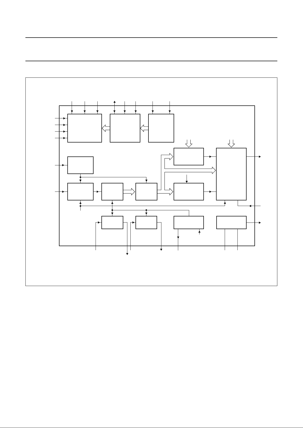
Fig.1 Block diagram.
handbook, full pagewidth
MBH229
STEP
IMPROVEMENT
PROCESSOR
SMART
SHARPNESS
CONTROLLER
CONTOUR
PROCESSOR
CLAMPS
DELAY
DELAY DELAY IPTAT
BANDGAP
BLACK
INSERTION
CLAMP
amplitude
selection
UIN
YIN
SANDCASTLE
input
UOUT
VIN VOUT R
ext
VCCGND
SANDCASTLE
DETECTOR
I
2
C-BUS
CONTROLLER
AMS CFS FHS
PIN-TO-I
2
C-BUS
INTERFACE
6-BIT
ADC
contour filter
selection
line frequency
selection
line width
steepness coring peaking
24918 167
5
1
PEAK
11
LWC
STEEP
4
22
14 8 17
SDA
13
ADR
6
SCL
12
ADEXT2
TDA9177
10
ADEXT1
3
COR
2
21 19
V
ref
SNC
YOUT
23
15
20
1997 Dec 01 4
Philips Semiconductors Product specification
YUV transient improvement processor TDA9177
PINNING
SYMBOL PIN DESCRIPTION
SANDCASTLE 1 sandcastle input
COR 2 coring level input
ADEXT1 3 ADC input 1
LWC 4 line width control input
YIN 5 luminance input
ADR 6 I
2
C-bus address input
UIN 7 colour U input
CFS 8 contour filter select input
VIN 9 colour V input
ADEXT2 10 ADC input 2
PEAK 11 peaking amplitude input
SCL 12 serial clock input (I
2
C-bus)
SDA 13 serial data input/output
(I
2
C-bus)
AMS 14 amplitude select input
SNC 15 smart noise control input
VOUT 16 colour V output
FHS 17 line frequency select input
UOUT 18 colour U output
GND 19 system ground
YOUT 20 luminance output
V
CC
21 supply voltage
STEEP 22 steepness control input
V
ref
23 reference voltage output
R
ext
24 resistor reference
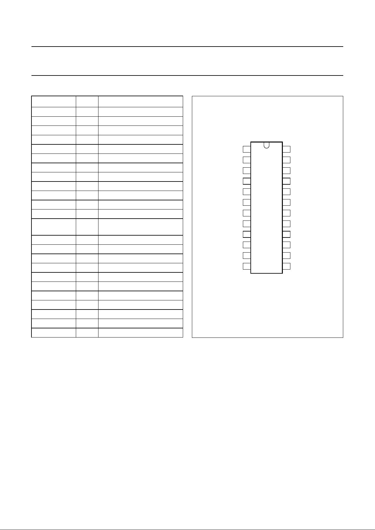
Fig.2 Pin configuration.
handbook, halfpage
TDA9177
MBH228
1
2
3
4
5
6
7
8
9
10
11
12
24
23
22
21
20
19
18
17
16
15
14
13
SANDCASTLE
COR
ADEXT1
ADEXT2
PEAK
SCL
FHS
SDA
AMS
SNC
LWC
YIN
ADR
UIN
CFS
VIN
R
ext
V
ref
V
CC
VOUT
UOUT
GND
YOUT
STEEP

1997 Dec 01 5
Philips Semiconductors Product specification
YUV transient improvement processor TDA9177
FUNCTIONAL DESCRIPTION
Y-input selection and amplification
The dynamic range of the luminance input amplifier and
output amplifier can be switched between 0.315 V and
1.0 V typically (excluding sync), either externally
(pin AMS) or by I
2
C-bus (bit AMS of the control register).
Amplitudes outside the corresponding maximum specified
range will be clipped smoothly. The sync part is processed
transparently to the output, independently of the feature
settings. The input is clamped during the HIGH period of
the CLP, defined by the sandcastle reference, and should
be DC-decoupled with an external capacitor. During the
clamp pulse, an artificial black level is inserted in the input
signal to correctly preset the internal circuitry.
The input amplifier drives a delay line of four delay
sections, which form the core of the sharpness
improvement processor.
Sharpness improvement processor
The sharpness improvement processor increases the
slope of large luminance transients of vertical objects and
enhances transients of details in natural scenes by contour
correction. It comprises three main processing units, these
being the step improvement processor, the contour
processor and the smart sharpness controller.
STEP IMPROVEMENT PROCESSOR
The step improvement processor (see Fig.9) comprises
two main functions:
1. the MINMAX generator
2. the MINMAX fader.
The MINMAX generator utilizes 5 taps of an embedded
luminance delay line to calculate the minimum and
maximum envelope of all signals momentarily stored in the
delay line. The MINMAX fader chooses between the
minimum and maximum envelopes, depending on the
polarity of a decision signal derived from the contour
processor. Figures 4, 5 and 6 show some waveforms of
the step improvement processor and illustrate that fast
transients result with this algorithm. The MINMAX
generator also outputs a signal that represents the
momentary envelope of the luminance input signal.
This envelope information is used by the smart sharpness
controller.
Limited line width control (also called aperture control) can
be performed externally (pin 4, LWC) or by I2C-bus
(LW-DAC). Line width control can be used to compensate
for horizontal geometry because of the gamma or
blooming of the spot of the CRT.
T
HE CONTOUR PROCESSOR
The contour processor comprises two contour generators
with different frequency characteristics. The contour
generator generates a second-order derivative of the
incoming luminance signal and is used both as a decision
signal for the step improvement processor and as a
luminance correction signal for the smart sharpness
controller. In the smart sharpness controller, this
correction signal is added to the proper delayed original
luminance input signal, making up the peaking signal for
detail enhancement. The peaking path is allowed to select
either the narrow- or wide-peaked contour generators
either externally (pin 8, CFS) or by I
2
C-bus (bit CFS in the
control register). The step improvement circuitry always
selects the wide-peaked contour filter.
The contour generators utilize 3 taps (narrow band) or
5 taps (broad band) of the embedded luminance delay
lines. Figures 11 and 12 illustrate the normalized
frequency transfer of both the narrow and wide contour
filters.
S
MART SHARPNESS CONTROLLER
The smart sharpness controller (see Fig.10) is a fader
circuit that fades between peaked luminance and
step-improved luminance, defined by the output of a step
discriminating device known as the step detector. It also
contains a variable coring level stage.
The step detector behaves like a band-pass filter, so both
amplitude of the step and its slope add to the detection
criterion. The smart sharpness controller has four user
controls:
1. Steepness control
2. Peaking control
3. Coring level control
4. Smart Noise control.
Control settings can be performed either by the I2C-bus or
externally by pin, depending on the status of the I2C-bus
bit STB.
The steepness setting controls the amount of steepness in
the edge-correction processing path. The peaking setting
controls the amount of contour correction for proper detail
enhancement.

1997 Dec 01 6
Philips Semiconductors Product specification
YUV transient improvement processor TDA9177
The envelope signal generated by the step improvement
processor modulates the peaking setting in order to
reduce the amount of peaking for large sine excursions
see Figs 7 and 8.
The coring setting controls the coring level in the peaking
path for rejection of high-frequency noise. All three
settings facilitate reduction of the impact of the sharpness
features, e.g. for noisy luminance signals.
An external noise detector and a user-preferred noise
algorithm are needed to make a fully automatic I2C-bus
controlled smart sharpness control.
An on-board, hard-wired smart sharpness algorithm can
be executed by driving pin SNC with the output of an
external noise detector. This pin, however, is active both in
I2C-bus and pin mode. Figures 13 and 14 illustrate the
impact of the noise control voltage at pin SNC on the user
settings.
Figure 15 shows the relationship between the feature
settings STEEP, COR, PEAK, LWC and their
corresponding pin voltages.
Chrominance compensation
The chrominance delay lines compensate for the delay of
the luminance signal in the step improvement processor,
to ensure a correct colour fit. No delay compensation will
be performed in the chrominance path for line-width
corrections in the luminance path.
Successive approximation ADC
Pins ADEXT1 and ADEXT2 are connected to a 6-bit
successive approximation ADC, via a multiplexer.
The multiplexer toggles between the inputs with each field.
For each field flyback, a conversion is started for either of
the two inputs and the result is stored in the corresponding
bus register, ADEXT1 or ADEXT2.
In this way, any analog, slowly varying signal can be given
access to the I
2
C-bus. If a register access conflict occurs,
the data of that register is made invalid by setting the flag
bit DV (Data Valid) to zero.
I
2
C-bus
At power up, the bit STB (standby) in the control register is
reset, to leave control to the pins. However, the I2C-bus is
at standby and responds if properly addressed. By setting
STB to logic 1, the control of all features is instead left to
the I2C-bus registers. The PDD bit (Power Down Detected)
in the status register is set each time an interruption of the
supply power occurs and is reset only by reading the
status register. A 3-bit identification code can also be read
from the status register, which can be used to
automatically configure the application by software.
The input control registers can be written sequentially by
the I2C-bus by the embedded automatic subaddress
increment feature or by addressing it directly. The output
control functions cannot be addressed separately.
Reading out the output control functions always starts at
subaddress 00 and all subsequent words are read out by
the automatic subaddress increment procedure. The I2C
address is 40H if pin 6 (ADR) is connected to ground and
E0H if pin 6 (ADR) is connected to pin 23 (V
ref
).
I
2
C-bus specification
Slave address
Auto-increment mode available for subaddresses.
A6 A5 A4 A3 A2 A1 A0 R/W
ADR 1 ADR 0 0 0 0 X

1997 Dec 01 7
Philips Semiconductors Product specification
YUV transient improvement processor TDA9177
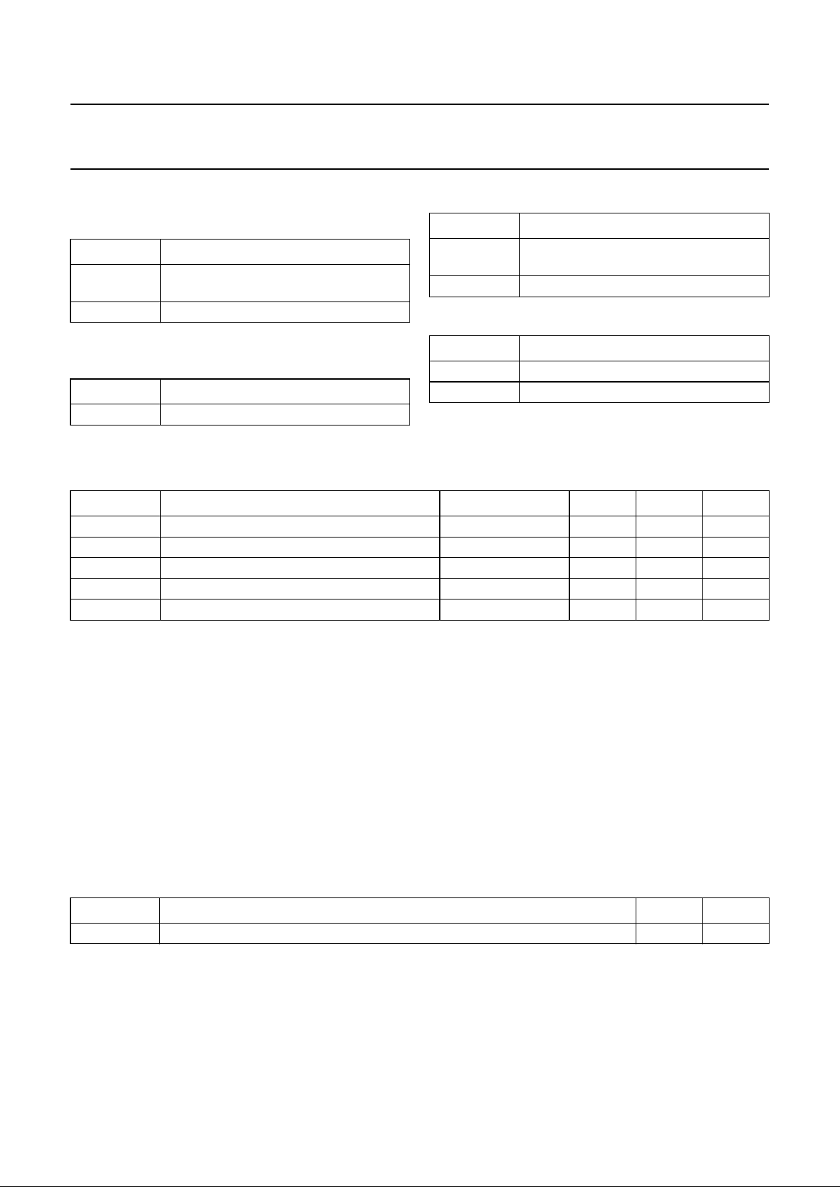
Control functions
FUNCTIONS TYPE SUBADDRESS
DATA BYTE
D7 D6 D5 D4 D3 D2 D1 D0
Inputs
Control REG 00 X X X X CFS FHS AMS STB
Peaking DAC 01 X X PK5 PK4 PK3 PK2 PK1 PK0
Steepness DAC 02 X X SP5 SP4 SP3 SP2 SP1 SP0
Coring DAC 03 X X CR5 CR4 CR3 CR2 CR1 CR0
Line width DAC 04 X X LW5 LW4 LW3 LW2 LW1 LW0
Outputs
Status REG 00 0 0 0 0 ID2 ID1 ID0 PDD
ADEXT1 (output) REG 01 0 DV AD5 AD4 AD3 AD2 AD1 AD0
ADEXT2 (output) REG 02 0 DV AD5 AD4 AD3 AD2 AD1 AD0
INPUT SIGNALS
Table 1 Address selection
Table 2 Standby
Table 3 Amplitude selection
Table 4 Line frequency selection
Table 5 Contour filter selection
ADR FUNCTION
0I
2
C address is 40H
1I
2
C address is E0H
STB FUNCTION
0 pin mode
1I
2
C-bus mode
AMS FUNCTION
0 0.315 V luminance
1 1.0 V luminance
FHS FUNCTION
01f
H
12f
H
CFS FUNCTION
0 narrow contour filter
1 wide contour filter
Table 6 Peaking amplitude
Table 7 Steepness correction
Table 8 Coring level
Table 9 Line width correction
PK5 to PK0 FUNCTION
000000 0%
111111 100%
SP5 to SP0 FUNCTION
000000 0%
111111 100%
CR5 to CR0 FUNCTION
000000 0%
111111 100%
LW5 to LW0 FUNCTION
000000 0%
111111 100%
1997 Dec 01 8
Philips Semiconductors Product specification
YUV transient improvement processor TDA9177
OUTPUT SIGNALS
Table 10 Power Down Detection (PDD)
Table 11 Identification
(version number or derivative type)
PDD FUNCTION
0 no power down detected since last read
action
1 power down detected
ID2 to ID0 FUNCTION
000 TDA9177/N1
Table 12 Data valid of ADC registers
Table 13 Bits AD5 to AD0
DV FUNCTION
0 data not valid because of possible
register access collision
1 data valid
AD5 to AD0 FUNCTION
000000B 0 V
111111B 0.5V
ref
LIMITING VALUES
In accordance with the Absolute Maximum Rating System (IEC 134).
QUALITY SPECIFICATION
Quality level in accordance with
“SNW-FQ-611 part E”
.
All pins are protected against ESD by means of internal clamping diodes. The protection circuit meets the specification:
Human body model (100 pF, 1500 Ω): All pins >3000 V.
Machine model (200 pF, 0 Ω): All pins >300 V.
Latch-up:
At an ambient temperature of 70 °C, all pins meet the specification:
I
trigger
> 100 mA or V
pin
> 1.5V
CC(max)
I
trigger
< −100 mA or V
pin
< −0.5V
CC(max)
THERMAL CHARACTERISTICS
SYMBOL PARAMETER CONDITIONS MIN. MAX. UNIT
V
CC
supply voltage −0.5 +8.8 V
V
i
input voltage on any input −0.5 VCC+ 0.5 V
V
o
output voltage of any output −0.5 VCC+ 0.5 V
T
stg
storage temperature −55 +150 °C
T
amb
operating ambient temperature −10 +70 °C
SYMBOL PARAMETER VALUE UNIT
R
th j-a
thermal resistance from junction to ambient in free air <59 K/W
1997 Dec 01 9
Philips Semiconductors Product specification
YUV transient improvement processor TDA9177
CHARACTERISTICS
V
CC
=8V; R
ref
=10kΩ±2%; T
amb
=25°C; unless otherwise specified.
SYMBOL PARAMETER CONDITIONS MIN. TYP. MAX. UNIT
Supplies
M
AIN SUPPLY V
CC
(PIN 21)
V
CC
supply voltage 7.2 8.0 8.8 V
I
CC
supply current 1fH mode − 40 − mA
2f
H
mode − 45 − mA
REFERENCE SUPPLY V
ref
(PIN 23)
V
ref
reference supply voltage 3.90 4.05 4.20 V
I
L(max)
maximum load current 1.0 −−mA
RESISTOR REFERENCE R
ext
(PIN 24)
V
Rref
resistor supply voltage − 2 − V
R
ref
resistor value − 10 − kΩ
Luminance input/output selection
L
UMINANCE INPUT YIN (PIN 5)
V
i(Y)
luminance input voltage AMS = LOW − 0.315 0.42 V
AMS = HIGH − 1.0 1.33 V
V
i(Yclamp)
luminance input voltage level during
clamping
− 4.0 − V
I
ib(Y)
luminance input bias current no clamp −−0.1 µA
LUMINANCE INPUT VOLTAGE RANGE SELECTION AMS (PIN 14); note 1
V
AMSL
input voltage for low luminance range −−0.5 V
V
AMSH
input voltage for high luminance range 3.5 − 5.5 V
 Loading...