

Philips tda9171 DATASHEETS
INTEGRATED CIRCUITS
DATA SH EET
TDA9171
YUV picture improvement
processor based on histogram
modification and blue stretch
Preliminary specification
Supersedes data of 1995 Aug 01
File under Integrated Circuits, IC02
1996 Jun 17
Philips Semiconductors Preliminary specification
YUV picture improvement processor based
TDA9171
on histogram modification and blue stretch
FEATURES
• Picture content dependent non-linear Y and U,V
processing by luminance histogram analysis
• TV standard independent
• Incredible blue stretch
• Optional YC-processing.
GENERAL DESCRIPTION
The TDA9171 is a transparent analog video processor
with YUV input and output interfaces.
The luminance transfer is controlled in a non-linear way by
the distribution, in 5 discrete histogram sections, of the
luminance values measured in a picture. As a result, the
QUICK REFERENCE DATA
SYMBOL PARAMETER MIN. TYP. MAX. UNIT
V
CC
supply voltage 7.2 − 8.8 V
contrast ratio of the most important parts of the scene will
be improved.
So as to maintain a proper colour reproduction the
saturation of the −U and −V colour difference signals are
also controlled as a function of the actual non-linearity in
the luminance channel.
Optionally, the YUV blue stretch circuitry can be activated
which offsets colours near white towards blue.
The supply voltage is 8 V.
The device is contained in a 20 lead dual in-line package.
ORDERING INFORMATION
TYPE
NUMBER
TDA9171 DIP20 plastic dual in-line package; 20 leads; (300 mil); no heat spreader SOT146-1
NAME DESCRIPTION VERSION
PACKAGE
1996 Jun 17 2
Philips Semiconductors Preliminary specification
YUV picture improvement processor based
on histogram modification and blue stretch
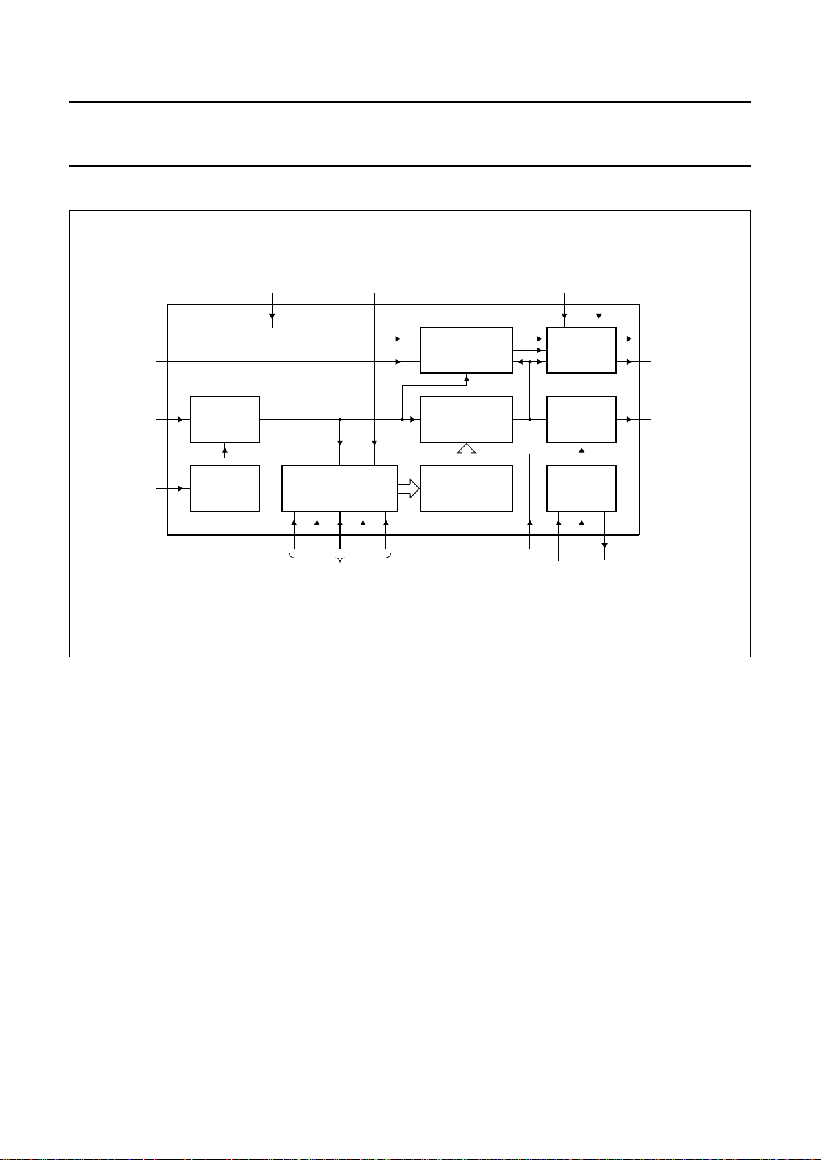
BLOCK DIAGRAM
book, full pagewidth
2
UIN
3
VIN
7
YIN
5
SC
AMPLIFIER
TIMING
CONTROL
INPUT
AND
AMPSEL
AMPSEL
TAUHM BLM BLG
68
TDA9171
HISTOGRAM
MEASUREMENT
9 10 11 12 13
SATURATION
COMPENSATION
NON-LINEAR
AMPLIFIER
HISTOGRAM
PROCESSOR
AMPLIFIER
4
20 1
BLUE
STRETCH
OUTPUT
AMPSEL
SUPPLY
AND
BIASING
16 15 17
TDA9171
19
UOUT
18
VOUT
14
YOUT
MBE990
HM1 to HM5
Fig.1 Block diagram.
NLC
V
EE
CC
V
ref
V
1996 Jun 17 3
Philips Semiconductors Preliminary specification
YUV picture improvement processor based
on histogram modification and blue stretch
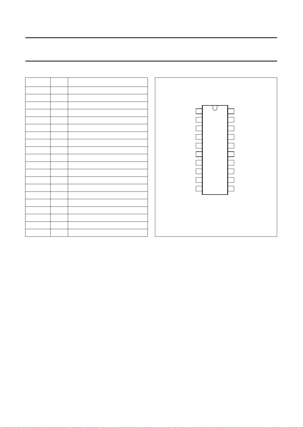
PINNING
SYMBOL PIN DESCRIPTION
BLG 1 blue stretch gain input
UIN 2 U colour difference input −UIN
VIN 3 V colour difference input −VIN
NLC 4 non-linear gain control input
SC 5 sandcastle input
AMPSEL 6 amplitude select input
YIN 7 luminance input
TAUHM 8 time constant histogram input
HM1 9 histogram segment memory 1 input
HM2 10 histogram segment memory 2 input
HM3 11 histogram segment memory 3 input
HM4 12 histogram segment memory 4 input
HM5 13 histogram segment memory 5 input
YOUT 14 luminance output
V
EE
V
CC
V
ref
VOUT 18 colour difference output −VOUT
UOUT 19 colour difference output −UOUT
BLM 20 activation level blue stretch input
15 ground
16 supply voltage
17 reference voltage output
handbook, halfpage
AMPSEL
1
BLG
2
UIN
3
VIN
4
NLC
5
SC
YIN
TAUHM
HM1
HM2
6
7
8
9
10
TDA9171
MBE989
Fig.2 Pin configuration.
TDA9171
20
BLM
19
UOUT
18
VOUT
V
17
ref
V
16
CC
V
15
EE
14
YOUT
13
HM5
12
HM4
11
HM3
FUNCTIONAL DESCRIPTION
Input selection and amplification
The dynamic range of the luminance input amplifier is
0.3 or 1 V (excluding sync) typically, depending on the
logic level at pin AMPSEL (pin 6). Amplitudes which
extend the corresponding specified range will be clipped
smoothly, however, the sync is processed to the output
transparently. The non-linear gain setting will have
minimum effect.
Optionally, in the 1 V input mode, the Y output can be
attenuated by a factor of 0.7 by means of an intermediate
level at pin AMPSEL. This option is meant for correctly
interfacing the combed CVBS signal to the video
processor in a YC-application.
The input is clamped during the logic HIGH period of the
CLP, defined by the sandcastle reference, and should be
DC-decoupled with an external capacitor.
1996 Jun 17 4
Histogram measurement
For the luminance signal the histogram distribution is
measured in real-time over five segments (HM1 to HM5) in
each field. During the period that the luminance is in one
segment, a corresponding external capacitor HMx is
loaded via a current source. At the end of the field five
segment voltages are stored from the external capacitors
into on-board memories. The external capacitors are
discharged and the measurements are repeated.
Parts in the scene that do not contribute to the information
in that scene should be omitted from the histogram
measurement. No measurements are performed during
the blanking period defined by the sandcastle.
The miscount detector disables measurements until it
detects changing parts. Additionally, luminance values
close to full scale (or white) do not contribute as well in
order to maintain the absolute light output. This procedure
is allowed because the eye is less sensitive to detail in
white.

Philips Semiconductors Preliminary specification
YUV picture improvement processor based
on histogram modification and blue stretch
As the miscount detector shortens the effective
measurement period and, because of spreads of internal
and external components, the current source is controlled
in a closed-loop to provide a constant value of the sum of
the segment voltages. The dominant time constant of the
closed-loop is external and can be tuned with an
appropriate capacitor value at pin TAUHM (pin 8).
Processing of the measured histogram value
FIELD AVERAGING OF HISTOGRAM VALUES
With very rapid picture changes, also related to the field
interlace, flicker might result. The histogram values are
averaged at the field rate thus reducing the flicker effects.
The time constant of the averaging process is adapted to
the speed of the histogram changes.
DAPTIVE WHITE-POINT STRETCHING
A
For dominant HM4 and HM5 voltages, or large white parts,
the histogram conversion procedure makes a transfer with
large gain in the white parts, however the amount of light
coming out of the scene is considerably reduced. The
white stretcher introduces additional overall gain for
increased light production and, as a result, violates the
principle of having a full scale reference.
TANDARD DEVIATION
S
For scenes, in which segments of the histogram
distribution are very dominant with respect to the others,
the non-linear amplification should be reduced in
comparison to scenes with a flat histogram distribution.
The standard deviation detector measures the spread of
the histogram distribution in the segments HM1 to HM5
and modulates the user setting of the non-linear amplifier.
Non-linear amplifier
The stored segment voltages relative to their average
value, averaged over two fields, determine the individual
gain of each segment in such a way that continuity is
guaranteed for the complete range. The maximum and
minimum gain of each segment is limited. Apart from the
adaptive white-point stretching the black and white
references are not affected by the non-linear processing.
The amount of linearity can be controlled externally by the
NLC pin (Non Linearity Control).
TDA9171
Colour compensation
Non-linear luminance processing influences the colour
reproduction, mainly the colour saturation. Therefore, the
U and V signals are also processed for saturation
compensation.
By convention −U and −V signals must be supplied to the
TDA9171. The −U and −V input signals are clamped
during the logic HIGH period of CLP, defined by the
sandcastle reference. In YC-applications just one colour
difference channel is required for processing the chroma
signal. However, external decoupling capacitors should be
applied to both inputs UIN and VIN. The external coupling
capacitor value should be such that the burst period of the
chroma signal is very softly clamped.
The processing is dependent on the amplitude and sign of
the colour difference signals whenever the blue stretch
circuitry is activated. Therefore, both the polarity and the
nominal amplitude of the colour difference signals are
relevant when using the blue stretch facility.
Blue stretch
The blue stretch circuit is intended to shift colours near
white, with sufficient contrast values, towards more blue
coloured white to give a brighter impression. The
chromaticity shift is proportional to the excess of the
contrast value of a white video signal with respect to a user
adjustable minimum level, defined by a voltage at
pin BLM. In this way blue shift in, for instance, human
faces can be prevented. The global amount of blue shift is
defined by the voltage level at pin BLG. The direction of
shift in the colour triangle is fixed by hardware.
It should be noted that the colour shift is different with a
wrong polarity of the colour difference signals. The
preferred BLG and BLM settings will be related to the
actual nominal amplitudes of the colour difference signals.
The blue stretch facility must be disabled in
YC-applications by setting both BLG and BLM to ground.
1996 Jun 17 5
 Loading...