

Philips tda3508 DATASHEETS

INTEGRATED CIRCUITS
DATA SH EET
TDA3508
Video control combination circuit
with automatic cut-off control
Product specification
Supersedes data of April 1993
File under Integrated Circuits, IC02
1996 Oct 25

Philips Semiconductors Product specification
Video control combination circuit with
automatic cut-off control
FEATURES
• Capacitive coupling of the colour difference and
luminance input signals with black level clamping in the
input stages
• Linear saturation control acting on the colour difference
signals
• (G−Y) and RGB matrix
• Linear transmission of inserted signals
• Equal black levels for inserted and matrixed signals
• Three identical channels for the RGB signals
• Linear contrast and brightness controls, operating on
both the inserted and matrixed RGB signals
• Peak beam current limiting input
• Clamping, horizontal and vertical blanking of the three
input signals controlled by a 3-level sandcastle pulse
• Three DC gain controls for the RGB output signals
(white point adjustment)
• Emitter-follower outputs for driving the RGB output
stages
• Input for automatic cut-off control with compensation for
leakage current of the picture tube.
TDA3508
GENERAL DESCRIPTION
The TDA3508 is an integrated circuit which performs video
control functions in a PAL/SECAM decoder for negative
colour difference signals −(R−Y) and −(B−Y).
The required input signals are luminance and colour
difference and a 3-level sandcastle pulse for control
purposes. Linear RGB signals can be inserted from an
external source. RGB output signals are available for
driving the video output stages. The circuit provides
automatic cut-off control of the picture tube.
ORDERING INFORMATION
TYPE
NUMBER
TDA3508 DIP28 plastic dual in-line package; 28 leads (600 mil) SOT117-1
NAME DESCRIPTION VERSION
PACKAGE
1996 Oct 25 2

Philips Semiconductors Product specification
Video control combination circuit with
TDA3508
automatic cut-off control
QUICK REFERENCE DATA
All voltages referenced to pin 24 (ground).
SYMBOL PARAMETER MIN. TYP. MAX. UNIT
V
P
I
P
V
15(p-p)
V
18(p-p)
V
17(p-p)
V
12,13,14(b-w)
V
10
V
20
V
19
V
16
T
amb
supply voltage (pin 6) − 12.0 − V
supply current − 95 − mA
composite video input signal (pin 15) (peak-to-peak value) − 0.45 − V
−(B−Y) colour difference input signal (pin 18)
− 1.33 − V
(peak-to-peak value)
−(R−Y) colour difference input signal (pin 17)
− 1.05 − V
(peak-to-peak value)
inserted RGB signals (black-to-white value)
− 1.0 − V
(pins 12, 13 and 14)
3-level sandcastle pulse (pin 10)
level 1 − 2.5 − V
level 2 − 4.5 − V
level 3 − 8.0 − V
control voltage for brightness (pin 20) 1.0 − 3.0 V
control voltage for contrast (pin 19) 2.0 − 4.3 V
control voltage for saturation (pin 16) 2.0 − 4.3 V
operating ambient temperature 0 − 70 °C
1996 Oct 25 3
Philips Semiconductors Product specification
Video control combination circuit with
automatic cut-off control
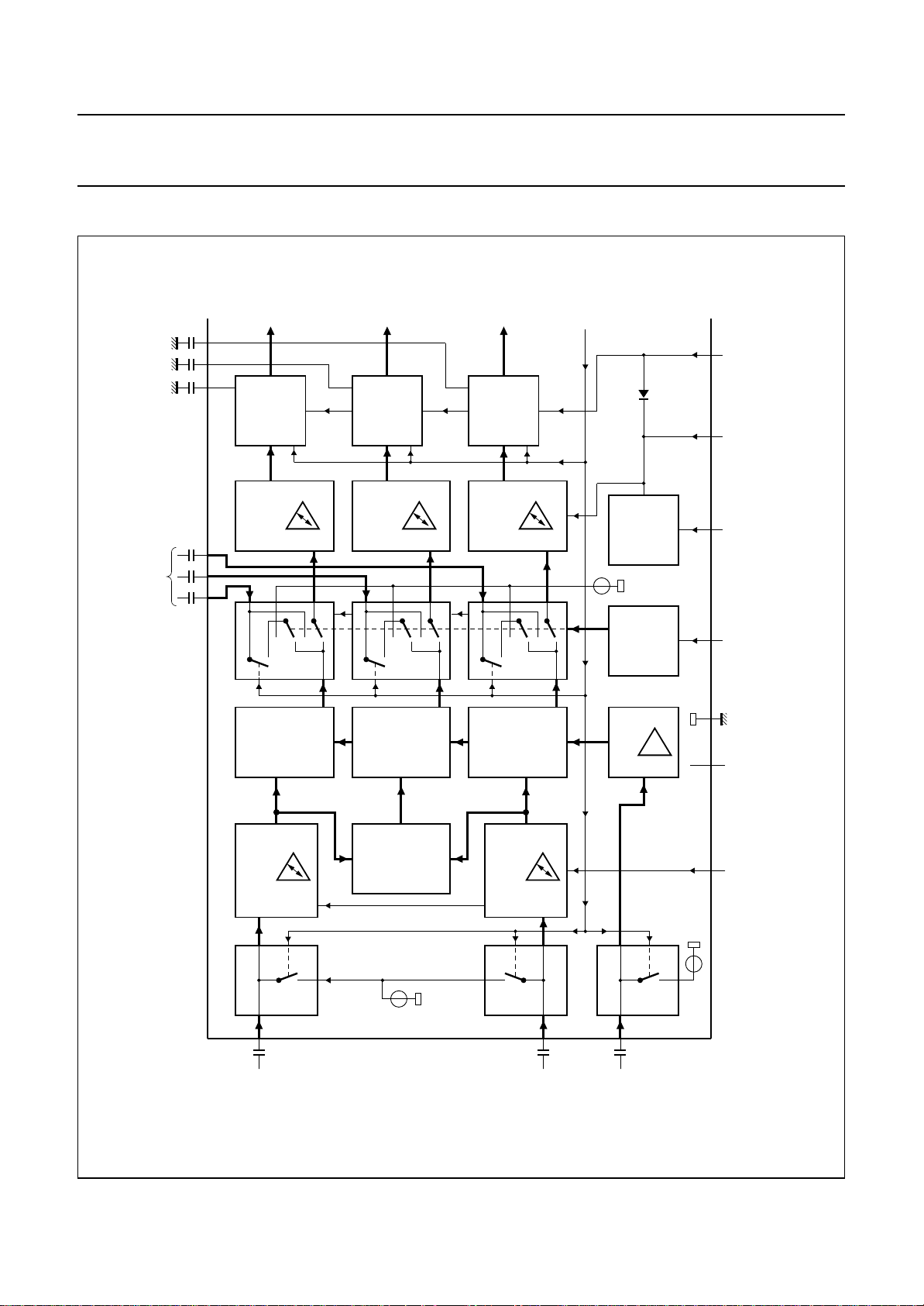
BLOCK DIAGRAM
green
CONTROL
CONTROL
BRIGHTNESS
BRIGHTNESS
CONTROL
CONTRAST
(b-w)
879
13 1214
red
CONTROL
BRIGHTNESS
CONTROL
CONTRAST
blue
CONTROL
BRIGHTNESS
CONTROL
CONTRAST
clamping pulse
4.5 V
SOURCE
CURRENT
TRESHOLD
DETECTOR
TDA3508
control
voltage
brightness
19 20
contrast control
voltage (2 to 4.3 V)
25
control input
for peak beam
current limiting
(1 to 3 V)
signal insertion 1 V
3 x SIGNAL SWITCH
R
MATRIX
(R−Y)
CONTROL
SATURATION
17 CLAMPING
11
SIGNAL
SWITCHES
DRIVER FOR
(1 V)
G
Y
(G−Y)
4.4 V
MATRIX
(G−Y)
MATRIX
Y
B
MATRIX
(B−Y)
CONTROL
SATURATION
18
CLAMPING
Y
clamping pulse
CLAMPING
15
Y
AMPLIFIER
10 dB
(part A)
TDA3508
246
16
2.9 V
input for signal
switching voltage
P
V
(+12 V)
saturation
(2 to 4.3 V)
control voltage
MSA736
handbook, full pagewidth
Fig.1 Block diagram (continued in Fig.2).
1996 Oct 25 4
−(R−Y)
(1.05 Vp-p)
−(B−Y)
(1.33 Vp-p)
composite
video
signal
(0.45 Vp-p)
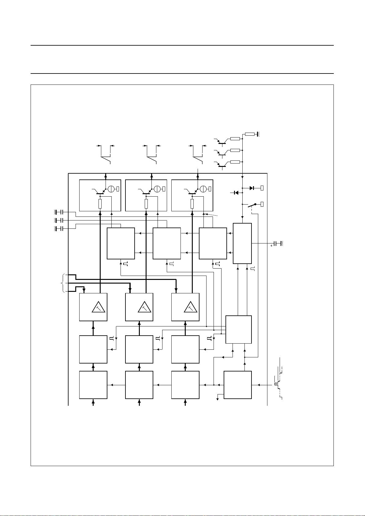
Philips Semiconductors Product specification
Video control combination circuit with
automatic cut-off control
storage capacitors
for cut-off
control
2428
red
1
CONTROLLED
OUTPUT
STAGE
2 V B/W
CONTROLLED
OUTPUT
STAGE
2 V B/W
green
3
5 blue
CONTROLLED
OUTPUT
STAGE
2 V B/W
R G B
control current
(3x)
TDA3508
MSA737
L
input for
voltage derived
from leakage
current of R
and cut-off
currents
(R or G or B)
26
+
(part B)
TDA3508
22 2123
(0 to 12 V)
white point adjustment
CONTROL
AMPLIFIER
INSERTION
PULSE
CURRENT
OF BLACK
MEASURING
BLANKING
red
&
V/I
CONVERTER
COMPARATOR
MR
CONTROL
AMPLIFIER
OF BLACK
INSERTION
PULSE
CURRENT
MEASURING
BLANKING
green
&
V/I
CONVERTER
COMPARATOR
MG
CONTROL
AMPLIFIER
OF BLACK
INSERTION
PULSE
CURRENT
MEASURING
BLANKING
blue
&
V/I
CONVERTER
COMPARATOR
MB
line 21 (1)
line 22 (1)
line 23 (1)
H + V
clamping
pulse
CIRCUIT
CLAMPING
SWITCHING AND
clamping
lines 21 to 23 (1)
lines 21 (1)
&
PULSE
FORMER
COUNTER
H + V
H
DETECTOR
SANDCASTLE
pulse
storage of leakage
current information
2.5 V
4.5 V
0
8 V
10 27
sandcastle
pulse
handbook, full pagewidth
Fig.2 Block diagram (continued from Fig.1).
1996 Oct 25 5
(1) After start of vertical blanking pulse.
 Loading...