

Philips tda3507 DATASHEETS

INTEGRATED CIRCUITS
DATA SH EET
TDA3507
Video control combination circuit
with automatic cut-off control
Product specification
File under Integrated Circuits, IC02
November 1987

Philips Semiconductors Product specification
Video control combination circuit with
TDA3507
automatic cut-off control
GENERAL DESCRIPTION
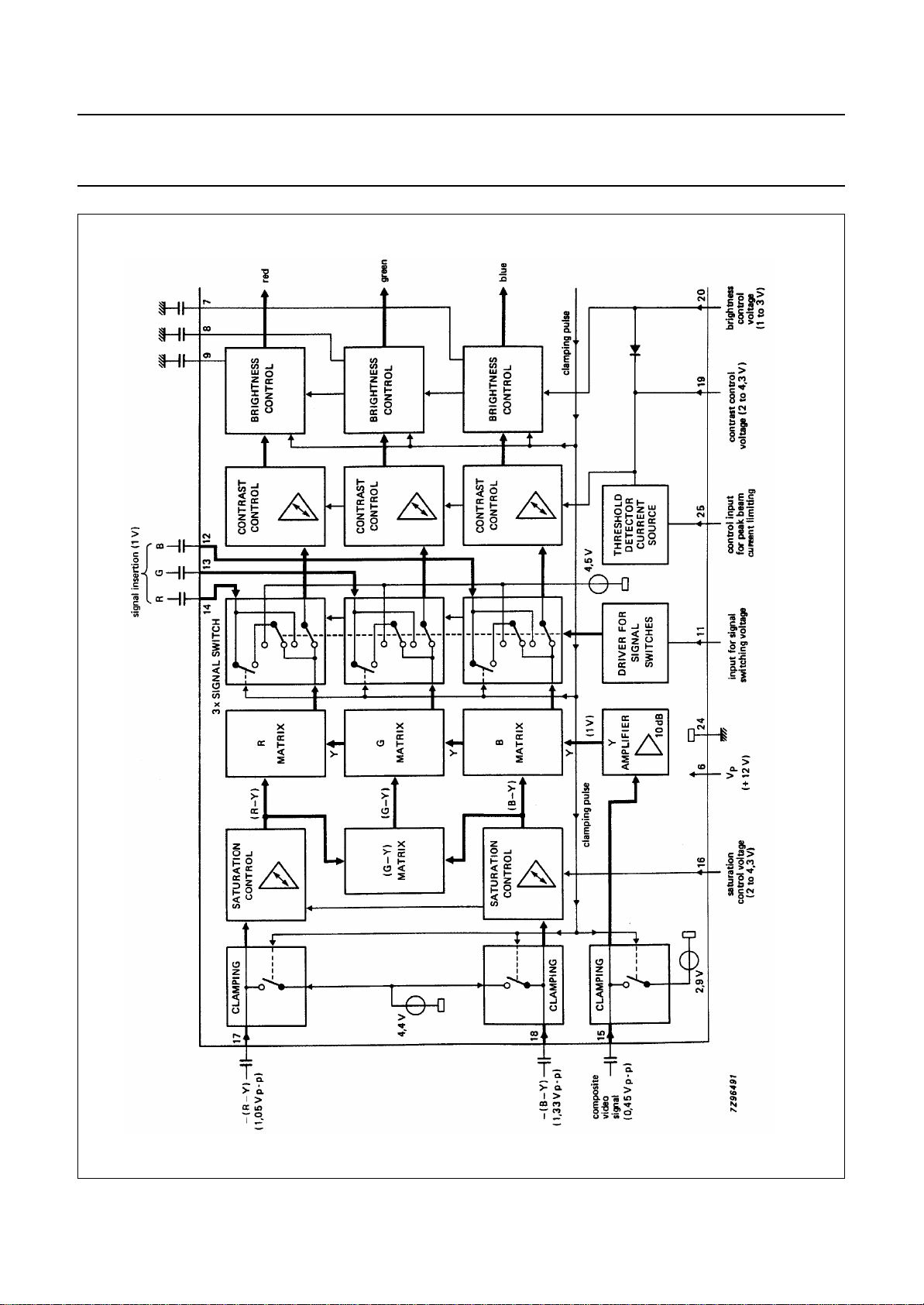
The TDA3507 is a monolithic integrated circuit which performs video control functions in a PAL/SECAM decoder.
The required input signals are: luminance and negative colour difference −(R−Y) and −(B−Y), and a 3-level sandcastle
pulse for control purposes. Linear RGB signals can be inserted from an external source. RGB output signals are available
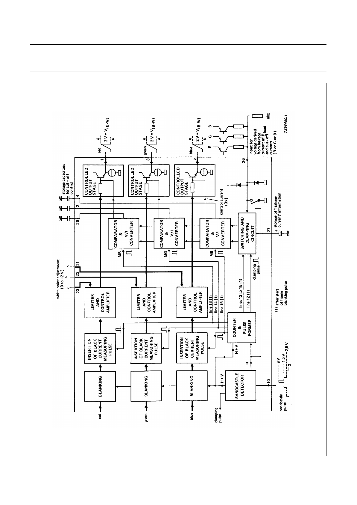
for driving the video output stages. This circuit provides automatic cut-off control of the picture tube.
The TDA3507 is the same as the TDA3505 but with RGB channel bandwidths of (typical) 16 MHz and an automatic
cut-off cycle that ends in line 15.
Features
• Capacitive coupling of the colour difference and
luminance input signals with black level clamping in the
input stages
• Linear saturation control acting on the colour difference
signals
• (G−Y) and RGB matrix
• Linear transmission of inserted signals
• Equal black levels for inserted and matrixed signals
• 3 identical channels for the RGB signals
• Linear contrast and brightness controls, operating on
both the inserted and matrixed RGB signals
• Peak beam current limiting input
• Clamping, horizontal and vertical blanking of the three
input signals controlled by a 3-level sandcastle pulse
• 3 DC gain controls for the RGB output signals (white
point adjustment)
• Emitter-follower outputs for driving the RGB output
stages
• Input for automatic cut-off control with compensation for
leakage current of the picture tube
QUICK REFERENCE DATA
PARAMETER CONDITIONS SYMBOL MIN. TYP. MAX. UNIT
Supply voltage (pin 6) V
Supply current I
Composite video input
signal (peak-to-peak value) V
Colour difference input
signals (peak-to-peak value)
−(B−Y) V
−(R−Y) V
Inserted RGB signals
(black-to-white value) V
Three-level sandcastle pulse V
Control voltage ranges
brightness V
contrast V
saturation V
= V
P
6-24
= I
P
6
15-24(p-p)
18-24(p-p)
17-24(p-p)
12,13,14-24
10-24
20-24
19-24
16-24
− 12 − V
− 100 − mA
− 0,45 − V
− 1,33 − V
− 1,05 − V
− 1,0 − V
− 2,5 − V
− 4,5 − V
− 8,0 − V
1,0 − 3,0 V
2,0 − 4,3 V
2,0 − 4,3 V
PACKAGE OUTLINE
28-lead DIL; Plastic (SOT117); SOT117-1; 1996 November 21.
November 1987 2
Philips Semiconductors Product specification
Video control combination circuit with
automatic cut-off control
TDA3507
November 1987 3
Fig.1 Part of block diagram, continued in Fig.2.
Philips Semiconductors Product specification
Video control combination circuit with
automatic cut-off control
TDA3507
November 1987 4
Fig.2 Part of block diagram, continued from Fig.1.

Philips Semiconductors Product specification
Video control combination circuit with
automatic cut-off control
PINNING
PIN DESCRIPTION
1 red output
2 green storage capacitor for cut-off control
3 green output
4 blue storage capacitor for cut-off control
5 blue output
6 positive supply voltage (+12 V)
7 blue storage for brightness
8 green storage for brightness
9 red storage for brightness
10 sandcastle pulse input
11 fast switch for RGB inputs
12 blue input (external signal)
13 green input (external signal)
14 red input (external signal)
15 luminance input
16 saturation control input
17 −(R−Y) colour difference input
18 −(B−Y) colour difference input
19 contrast control input
20 brightness control input
21 white point adjustment, blue
22 white point adjustment, green
23 white point adjustment, red
24 ground (0 V)
25 control input for peak beam current limiting
26 automatic cut-off control input
27 storage capacitor for leakage current
28 red storage capacitor for cut-off control
TDA3507
November 1987 5
 Loading...