

Philips TDA2557, TDA2555 Datasheet

INTEGRATED CIRCUITS
DATA SH EET
TDA2555
TDA2557
Dual TV sound demodulator circuits
Product specification
File under Integrated Circuits, IC02
March 1986

Philips Semiconductors Product specification
Dual TV sound demodulator circuits
TDA2555
TDA2557
GENERAL DESCRIPTION
The circuits incorporate two FM demodulator systems to perform the demodulator functions required in a dual sound
carrier TV system for demodulating the sound carriers.
The difference between TDA2555 and TDA2557 is the number of stages of the limiting amplifier.
• Eight (TDA2555) or five (TDA2557) stage limiting amplifier
• Quadrature demodulator for FM detection
• De-emphasis stage
• Output amplifier
• Mute function for each FM demodulator
QUICK REFERENCE DATA
Supply voltage (pins 13 and 15) V
Supply current (pins 13 and 15) I
AF output voltage (pins 2 and 8) V
Total harmonic distortion (note 1) THD < 0,1 %
Signal to weighted noise ratio (S + N)/N typ. 70 dB
P
P
o(rms)
typ. 12 V
typ. 24,5 mA
typ. 600 mV
PACKAGE OUTLINE
18-lead DIL; plastic (SOT102); SOT102-1; 1996 November 19.
March 1986 2
Philips Semiconductors Product specification
Dual TV sound demodulator circuits
TDA2555
TDA2557
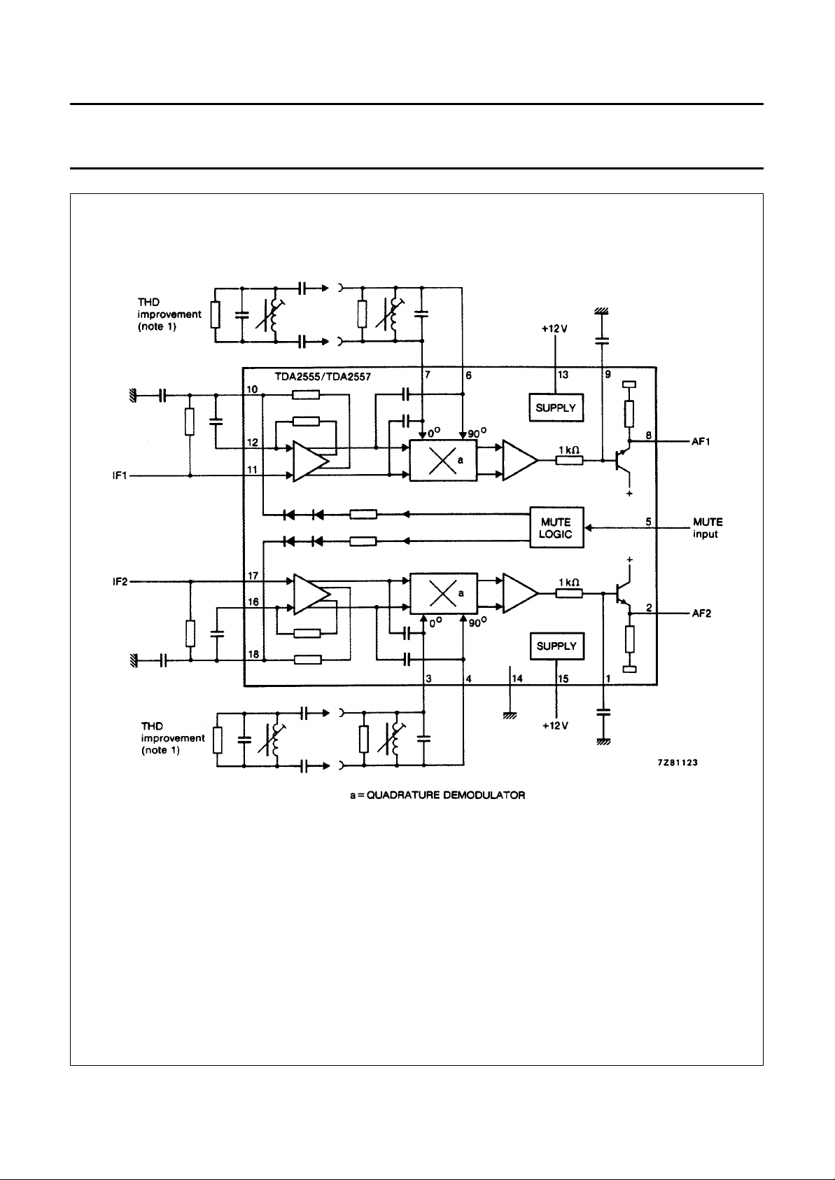
Fig.1 Block diagram.
TDA2555 with 8-stage limiting amplifier;
TDA2557 with 5-stage limiting amplifier.
March 1986 3
 Loading...