

Philips TBA120U Datasheet

INTEGRATED CIRCUITS
DATA SH EET
TBA120U
Sound I.F. amplifier/demodulator
for TV
Product specification
File under Integrated Circuits, IC02
March 1986

Philips Semiconductors Product specification
Sound I.F. amplifier/demodulator for TV TBA120U
GENERAL DESCRIPTION
The TBA120U is an i.f. amplifier with a symmetrical FM demodulator and an a.f. amplifier with adjustable output voltage.
The a.f. amplifier is also provided with an output for volume control and an input for VCR operation.
The input and output of the TBA120U are especially designed for LC-circuits, but the input can also be used with a
ceramic filter.
QUICK REFERENCE DATA
Supply voltage (pin 11) V
Supply current I
I.F. voltage gain at f = 5,5 MHz G
Input voltage starting limiting V
p
P
v if
i
typ. 12 V
typ. 13,5 mA
typ. 68 dB
typ. 30 µV
AM suppression at ∆f=±50 kHz α typ. 60 dB
A.F. output voltage adjustment range (pin 8) ∆V
o af
typ. 85 dB
A.F. output voltage at ∆f=±50 KHz (r.m.s. value)
at pin 8 V
at pin 12 V
o af (rms)
o af (rms)
typ. 1,2 V
typ. 1,0 V
PACKAGE OUTLINE
14-lead DIL; plastic (SOT27); SOT27-1; 1996 November 19.
March 1986 2
Philips Semiconductors Product specification
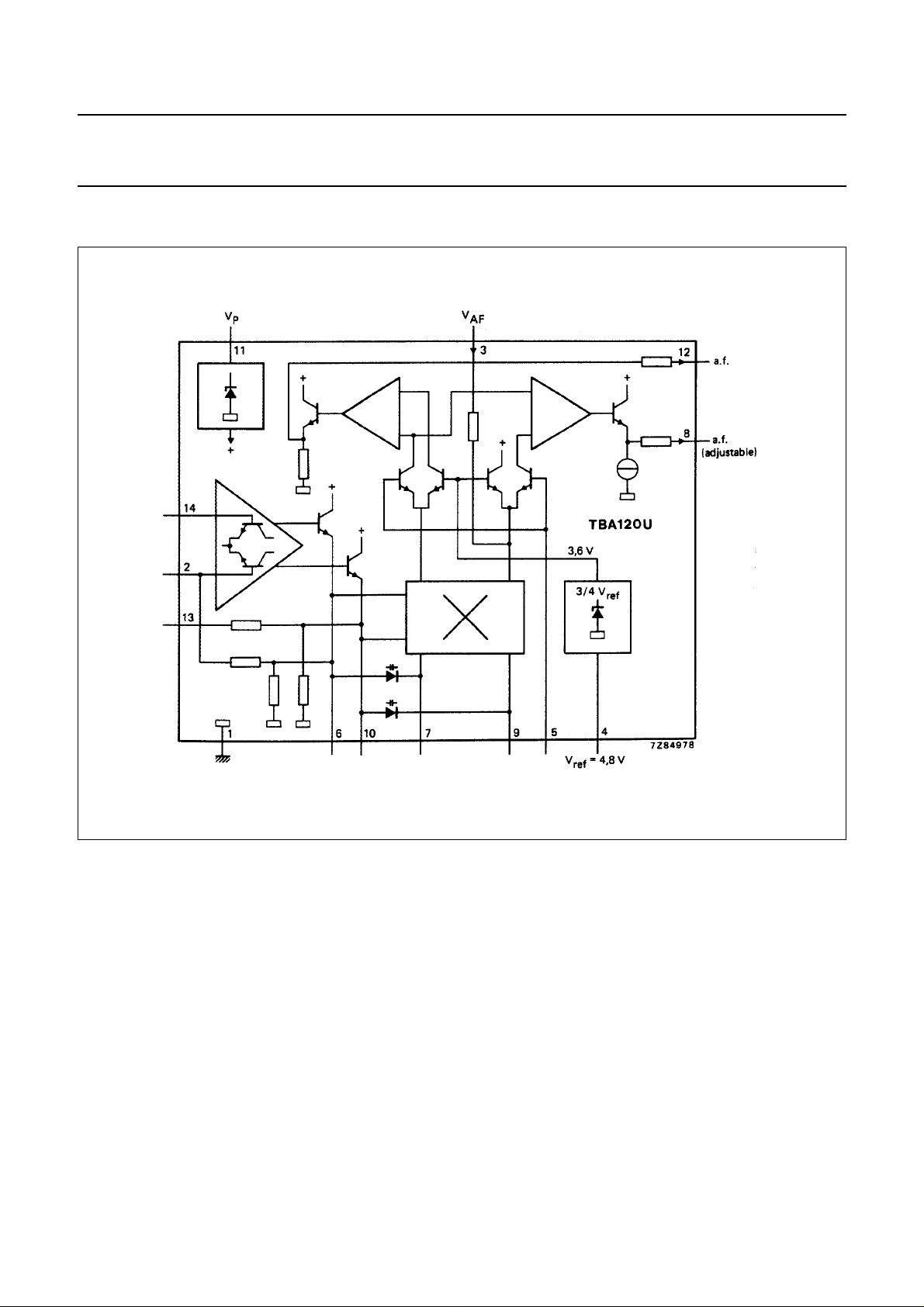
Sound I.F. amplifier/demodulator for TV TBA120U
Fig.1 Block diagram.
March 1986 3
 Loading...