

Philips SZA1010T Datasheet

INTEGRATED CIRCUITS
DATA SH EET
SZA1010
Digital Servo Driver 3 (DSD-3)
Preliminary specification
File under Integrated Circuits, IC01
1997 Apr 07

Philips Semiconductors Preliminary specification
Digital Servo Driver 3 (DSD-3) SZA1010
FEATURES
Servo functions
• 1-bit class-D focus actuator driver (4 Ω)
• 1-bit class-D radial actuator driver (4 Ω)
• 1-bit class-D sledge motor driver (2 Ω).
Other features
• Supply voltage 5 V only
• Small package (SOT163-1)
• Higher efficiency, compared with conventional drivers,
due to the class-D principle
• Built-in digital notch filters for higher efficiency
• Enable input for focus and radial driver
• Enable input for sledge driver
• 3-state input for radial driver
• Doubled clock frequency
• Differential outputs for all drivers
• Separate power supply pins for all drivers.
QUICK REFERENCE DATA
GENERAL DESCRIPTION
The SZA1010 or Digital Servo Driver 3 (DSD-3) consists of
1-bit class-D power drivers, which are specially designed
for digital servo applications. Three such amplifiers are
integrated in one chip, to drive the focus and radial
actuators and the sledge motor of a compact disc optical
system.
The main benefits of using this principle are its higher
efficiency grade compared to conventional analog power
amplifiers, its higher integration level, its differential output
and the fact that only a few external components are
needed. When using these digital power drivers in a digital
servo application, the statement ‘complete digital servo
loop’ becomes more realistic.
SYMBOL PARAMETER MIN. TYP. MAX. UNIT
V
DDD
V
DDA(F)
V
DDA(R)
V
DDA(S)
I
DDDq
I
DDA(F)
I
DDA(R)
I
DDA(S)
f
i(clk)
P
tot
T
amb
digital supply voltage 4.5 − 5.5 V
analog supply voltage focus actuator 4.5 − 5.5 V
analog supply voltage radial actuator 4.5 − 5.5 V
analog supply voltage sledge actuator 4.5 − 5.5 V
quiescent digital supply current −−10 µA
analog supply current focus actuator − 126 250 mA
analog supply current radial actuator − 20 250 mA
analog supply current sledge actuator − 150 560 mA
input clock frequency − 8.4672 10 MHz
total power dissipation − tbf − mW
operating ambient temperature −40 − +85 °C
ORDERING INFORMATION
TYPE
NUMBER
NAME DESCRIPTION VERSION
PACKAGE
SZA1010T SO20 plastic small outline package; 20 leads; body width 7.5 mm SOT163-1
1997 Apr 07 2
Philips Semiconductors Preliminary specification
Digital Servo Driver 3 (DSD-3) SZA1010
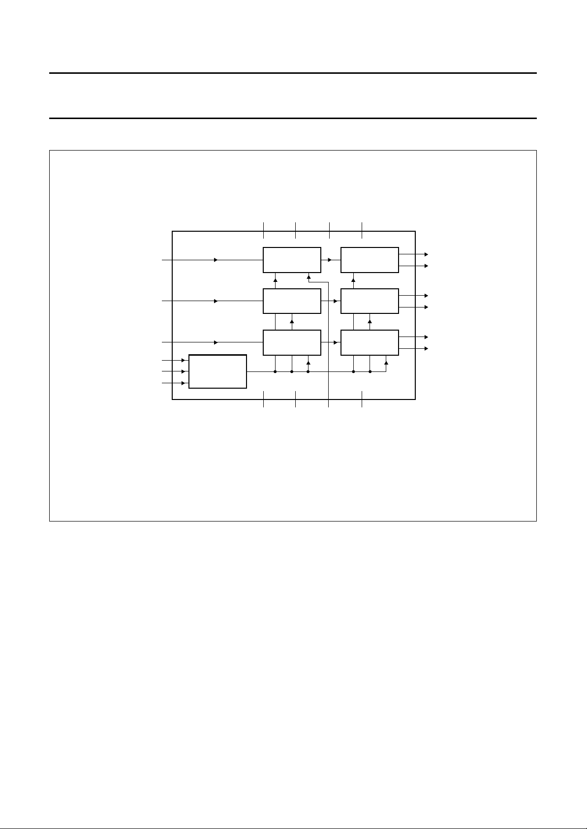
BLOCK DIAGRAM
book, full pagewidth
RAC
FOC
SLC
CLI
EN1
EN2
4
3
2
7
8
9
SZA1010
CONTROL
V
V
V
DDA(R)
DDD
613141
DIGITAL
NOTCH FILTER
DIGITAL
NOTCH FILTER
DIGITAL
NOTCH FILTER
5101718
V
SSA(R)
SSD
V
3-STATE
DDA(F)
V
DDA(S)
END STAGE
H−BRIDGE
END STAGE
H−BRIDGE
END STAGE
H−BRIDGE
V
SSA(S)/VSSA(F)
11
RA+
12
RA−
15
FO+
16
FO−
19
SL+
20
SL−
MBK013
Fig.1 Block diagram.
1997 Apr 07 3

Philips Semiconductors Preliminary specification
Digital Servo Driver 3 (DSD-3) SZA1010
PINNING
SYMBOL PIN DESCRIPTION
V
DDA(S)
SLC 2 PDM input for sledge driver
FOC 3 PDM input for focus driver
RAC 4 PDM input for radial driver
V
SSD
V
DDD
CLI 7 clock input
EN1 8 enable input 1
EN2 9 enable input 2
V
SSA(R)
RA+ 11 radial driver (positive output)
RA− 12 radial driver (negative output)
V
DDA(R)
V
DDA(F)
FO+ 15 focus driver (positive output)
FO− 16 focus driver (negative output)
3-STATE 17 radial 3-state input
/
V
SSA(S)
V
SSA(F)
SL+ 19 sledge driver (positive output)
SL− 20 sledge driver (negative output)
analog supply voltage for sledge
1
motor driver
5 digital ground
6 digital supply voltage
10 analog ground for radial driver
analog supply voltage for radial
13
driver
14 analog supply voltage for focus
analog ground for sledge
18
driver/focus
handbook, halfpage
V
DDA(S)
V
SSA(R)
1
2
SLC
FOC
3
RAC
4
V
5
SSD
V
DDD
CLI
EN1
EN2 RA−
6
7
8
9
10
SZA1010
MBK012
Fig.2 Pin configuration.
20
SL−
SL+
19
V
18
SSA(S)/VSSA(F)
3-STATE
17
16
FO−
15
FO+
V
14
DDA(F)
V
13
DDA(R)
12
11
RA+
1997 Apr 07 4

Philips Semiconductors Preliminary specification
Digital Servo Driver 3 (DSD-3) SZA1010
FUNCTIONAL DESCRIPTION
Principle of a class-D digital power driver
Figure 3 shows the block diagram of one of the digital
drivers integrated in the DSD-3. It consists of a timing
block and four CMOS switches. The input signal is a 1-bit
Pulse Density Modulated (PDM) signal, the output of the
digital servo ICs.
The maximum operating clock frequency of the device is
10 MHz. In combination with most frequently used Philips
digital servo ICs, the operating frequency of the digital
drivers is 8.4672 MHz (192 × 44.1 kHz). The sampling
frequency of the 1-bit code however is 2.1168 MHz, so
internally in the DSD-3 the clock speed of the switches will
be 2.1168 MHz.
The higher input clock frequency is used to make
non-overlapping pulses to prevent short-circuits between
the supply voltages. For the control of the switches, two
states can be distinguished. If the 1-bit code contains a
logic 1, switches A and D are closed and current will flow
in the direction as shown in Fig.4.
If the 1-bit code contains a logic 0, switches B and C are
closed and current will flow in the opposite direction, as
shown in Fig.5.
This indicates that the difference between the mean
number of ones and zeros in the PDM signal determines
the direction in which the actuator or motor will rotate.
If the mean number of ones and zeros is equal (Idle mode)
the current through the motor or actuator is alternated
between the positive and negative direction at a speed of
half the sample frequency of 2.1168 MHz. This results in a
high dissipation and the motor does not move.
The amplitude transfer as a function of frequency is given
in Fig.7.
Figure 7 shows that the filter has a zero on
filtering out the Idle pattern (101010). The output of this
filter is a three-level code (1.5-bit). For the control of the
switches three states (1.5-bit) can be distinguished: the
two states as described earlier and a third one. This state
is used when an idling pattern is supplied.
Switches C and D are closed (see Fig.8). In this Idle mode,
no current will flow and thus the efficiency will be improved.
This mode is also used to short-circuit the inductive
actuator/motor. In this way, high induction voltages are
prevented because the current can commutate via the
filter and the short-circuit in the switches. All three drivers
(radial, focus and sledge) contain a digital notch filter as
described (see Fig.6). Each driver has its own power
supply pins to reduce crosstalk due to of the relative high
current flowing through the pins.
Compared to the DSD-2, the DSD-3 has a 3-state mode
for the radial output, which is useful when active damping
of the radial actuator is needed. When fast access times
are required, the sledge has to move with high
accelerations. To prevent the radial actuator from moving
too far from its centre position due to the acceleration,
active damping is applied. In order to measure the
displacement of the radial actuator, the voltage induced by
the actuator itself is measured, which is proportional to its
speed. The damping consists of a sequence of controlling,
waiting, measuring and controlling etc. To be able to
measure the induced voltage properly, the influence of the
DSD-3 is eliminated by switching it into 3-state mode.
1
⁄2fs, thereby
To improve the efficiency, a digital notch filter is added at
the input of the digital drivers. This filters the Idle mode
pattern (1010101010 etc.) see Fig.6.
1997 Apr 07 5
 Loading...