

Philips System4 Seriver Installation Instructions Manual
Server
Philips
Communication,
Security & Imaging
Installation Instructions
Eng
®

2
3
IMPORTANT SAFEGUARDS
1. Read Instructions - All the safety and operating instructions should be read
before the unit is operated.
2. Retain Instructions - The safety and operating instructions should be
retained for future reference.
3. Heed Warnings - All warnings on the unit and in the operating instructions
should be adhered to.
4. Follow Instructions - All operating and use instructions should be followed.
5. Cleaning - Unplug the unit from the outlet before cleaning. Do not use
liquid cleaners or aerosol cleaners. Use a damp cloth for cleaning.
6. Attachments - Do not use attachments not recommended by the product
manufacturer as they may cause hazards.
7. Water and Moisture - Do not use this unit near water - for example, near a
bath tub, wash bowl, kitchen sink, or laundry tub; in a wet basement; near
a swimming pool; in an unprotected outdoor installation; or any area which
is classified as a wet location.
8. Accessories - Do not place this unit on an unstable stand, tripod, bracket,
or mount. The unit may fall, causing serious injury to a person and serious
damage to the unit. Use only with a stand, tripod, bracket, or mount
recommended by the manufacturer or sold with the product. Any
mounting of the unit should follow the manufacturer's instructions and
should use a mounting accessory recommended by the
manufacturer.
An appliance and cart combination should be moved with care.
Quick stops, excessive force, and uneven surfaces may cause the appliance
and cart combination to overturn.
9. Ventilation - Openings in the enclosure, if any, are provided for ventilation,
to ensure reliable operation of the unit, and to protect it from overheating.
These openings must not be blocked or covered. This unit should not be
placed in a built-in installation unless proper ventilation is provided or the
manufacturer's instructions have been adhered to.
10. Power Sources - This unit should be operated only from the type of power
source indicated on the marking label. If you are not sure of the type of
power supply you plan to use, consult your appliance dealer or local power
company. For units intended to operate from battery power or other
sources, refer to the operating instructions.
11. Grounding or Polarization - This unit may be equipped with a polarized
alternating-current line plug (a plug having one blade wider than the other).
This plug will fit into the power outlet only one way. This is a safety
feature. If you are unable to insert the plug fully into the outlet, try
reversing the plug. If the plug should still fail to fit, contact your electrician
to replace your obsolete outlet. Do not defeat the safety purpose of the
polarized plug.
Alternately, this unit may be equipped with a 3-wire grounding-type plug, a
plug having a third (grounding) pin. This plug will only fit into a
grounding-type power outlet. This is a safety feature. If you are unable to
insert the plug into the outlet, contact your electrician to replace your
obsolete outlet. Do not defeat the safety purpose of the grounding-type
plug.
12. Power Cord Protection - Power supply cords should be routed so that they are
not likely to be walked on or pinched by items placed upon or against them,
paying particular attention to cords and plugs, convenience receptacles, and
the point where they exit from the appliance.
13. Power Lines - An outdoor system should not be located in the vicinity of
overhead power lines or other electric light or power circuits or where it can
fall into such power lines or circuits. When installing an outdoor system,
extreme care should be taken to keep from touching such power lines or
circuits as contact with them might be fatal. U.S.A. models only - refer to
the National Electrical Code Article 820 regarding installation of CATV
systems.
14. Overloading - Do not overload outlets and extension cords as this can result
in a risk of fire or electric shock.
15. Object and Liquid Entry - Never push objects of any kind into this unit
through openings, as they may touch dangerous voltage points or short out
parts that could result in a fire or electric shock. Never spill liquid of any
kind on the unit.
16. Servicing - Do not attempt to service this unit yourself as opening or
removing covers may expose you to dangerous voltage or other hazards.
Refer all servicing to qualified service personnel.
17. Damage Requiring Service - Unplug the unit from the outlet and
refer servicing to qualified service personnel under the following conditions:
a. When the power supply cord or plug is damaged.
b. If liquid has been spilled or objects have fallen into the unit.
c. If the unit has been exposed to rain or water.
d. If the unit does not operate normally by following the operating
instructions. Adjust only those controls that are covered by the
operating instructions, as an improper adjustment of other controls
may result in damage and will often require extensive work by a
qualified technician to restore the unit to its normal operation.
e. If the unit has been dropped or the cabinet has been damaged.
f. When the unit exhibits a distinct change in performance--this indicates
a need for service.
18. Replacement Parts - When replacement parts are required, be sure the
service technician has used replacement parts specified by the
manufacturer or have the same characteristics as the original part.
Unauthorized substitutions may result in fire, electric shock, or other
hazards.
19. Safety Check - Upon completion of any service or repairs to this unit, ask
the service technician to perform safety checks to determine that the unit is
in proper operating condition.
20. Coax Grounding - If an outside cable system is connected to the unit, be
sure the cable system is grounded. U.S.A. models only--Section 810 of the
National Electrical Code, ANSI/NFPA No.70-1981, provides information
with respect to proper grounding of the mount and supporting structure,
grounding of the coax to a discharge unit, size of grounding conductors,
location of discharge unit, connection to grounding electrodes, and
requirements for the grounding electrode.
21. Lightning - For added protection of this unit during a lightning storm, or
when it is left unattended and unused for long periods of time, unplug it
from the wall outlet and disconnect the cable system. This will prevent
damage to the unit due to lightning and power line surges.
FCC & ICES INFORMATION
(U.S.A. and Canadian Models Only)
WARNING - This equipment has been tested and found to comply with the
limits for a Class A digital device, pursuant to Part 15 of the FCC Rules and
ICES-003 of Industry Canada. These limits are designed to provide reasonable
protection against harmful interference when the equipment is operated in a
commercial environment. This equipment generates, uses, and radiates radio
frequency energy and, if not installed and used in accordance with the
instruction manual, may cause harmful interference to radio communications.
Operation of this equipment in a residential area is likely to cause harmful
interference in which case the user will be required to correct the interference at
his own expense. Intentional or unintentional changes or modifications not
expressly approved by the party responsible for compliance shall not be made.
Any such changes or modifications could void the user's authority to operate the
equipment.
If necessary, the user should consult the dealer or an experienced radio/television
technician for corrective action . The user may find the following booklet
prepared by the Federal Communications Commission helpful: "How to
Identify and Resolve Radio-TV Interference Problems." This booklet is
available from the U.S. Government Printing Office, Washington, DC 20402,
Stock No.004-000-00345-4.
Warning: This is a Class A product. In a domestic
environment, this product may cause radio interference in
which case the user may be required to take adequate measures.
CAUTION: Lithium Battery – DANGER. The battery should be replaced
only by a service technician. The battery is a non-operator-replaceable cell.
There is a danger of explosion if the battery is incorrectly replaced. Replace
only with the same or equivalent type recommended by the manufacturer.
Dispose of used batteries according to the manufacturer’s instructions and local
laws.
Rack-mount Installation Considerations:
Elevated Operating Ambient—If installed in a closed or multi-unit rack
assembly, the operating ambient temperature of the rack environment may be
greater than the room ambient. Therefore, consideration should be given to
installing the equipment in an environment compatible with the
manufacturer’s maximum rated ambient temperature of 32°C (89.6°F).
4
SAFETY PRECAUTIONS
This label may appear on the bottom of the unit due to space
limitations.
The lightning flash with an arrowhead symbol within
an equilateral triangle is intended to alert the user to
the presence of uninsulated "dangerous voltage" within
the product's enclosure that may be of sufficient
magnitude to constitute a risk of electric shock to
persons.
The exclamation point within an equilateral triangle is
intended to alert the user to presence of important
operating and maintenance (servicing) instructions in
the literature accompanying the appliance.
Attention: Installation should be performed by
qualified service personnel only in accordance with the
National Electrical Code or applicable local codes.
Power Disconnect. Units with or without ON-OFF
switches have power supplied to the unit whenever the
power cord is inserted into the power source; however,
the unit is operational only when the ON-OFF switch
is in the ON position. The power cord is the main
power disconnect for all units.
SECURITE
En raison de limitation de place, cette étiquette peut être placée
sur le dessous de l'appareil.
L'éclair fléché dans un triangle équilatéral, avertit
l'utilisateur de la présence d'une "tension dangereuse"
non isolée à l'intérieur de l'appareil et d'une valeur
suffisante pour constituer un risque d'électrocution.
Le point d'exclamation contenu dans un triangle
équilatéral, avertit l'utilisateur de la présence, dans la
documentation qui accompagne l'appareil, de consignes
d'utilisation et de maintenance importantes.
Attention: L'installation doit être effectuée uniquement
par du personnel de service qualifié conformément à la
réglementation du Code Electrique National ou à la
réglementation locale.
Disjonction de l'alimentation. Les appareils avec ou
sans commutateurs ON-OFF sont alimentés à chaque
fois que le cordon d'alimentation est branché à la
source d'alimentation; toutefois, les appareils disposant
de commutateurs ON-OFF ne fonctionnnent que
lorsque le commutateur ON-OFF est sur la position
ON. Le cordon d'alimentation est la disjonction
d'alimentation principale pour tous les appareils.
CAUTION: TO REDUCE THE RISK OF
ELECTRICAL SHOCK, DO NOT OPEN
COVERS. NO USER SERVICEABLE PARTS
INSIDE. REFER SERVICING TO QUALIFIED
SERVICE PERSONNEL.
WARNING
TO PREVENT FIRE OR SHOCK HAZARD, DO
NOT EXPOSE UNITS NOT SPECIFICALLY
DESIGNED FOR OUTDOOR USE TO RAIN OR
MOISTURE.
DANGER: POUR ÉVITER TOUT RISQUE
D’ÉLECTROCUTION, NE PAS OUVRIR LE BOÎTIER.
IL N’Y A PAS DE PIÈCES REMPLAÇABLES À
L’INTÉRIEUR. POUR TOUTE RÉVISION,
S’ADRESSER À UN TECHNICIEN SPÉCIALISÉ.
ATTENTION
POUR ÉVITER LE RISQUE D’ÉLECTROCUTION OU
D’INCENDIE, NE PAS EXPOSER À LA PLUIE OU À
L’HUMIDITÉ UN APPAREIL NON CONÇU POUR
UNE UTILISATION EXTÉRIEURE.
5
SICHERHEITSVORKEHRUNGEN
Aus Platzgründen kann diese Warnung auf der Unterseite des
Gerätes angebracht sein.
Das Blitzsymbol im gleichseitigen Dreieck soll den
Benutzer auf nicht isolierte “Hochspannung” im
Gehäuse aufmerksam machen, die eventuell stark
genug ist, um einen elektrischen Schlag zu verursachen.
Das Ausrufezeichen im gleichseitigen Dreieck soll den
Benutzer auf wichtige Bedienungs- und
Wartungsanleitungen in der dem Gerät beigefügten
Literatur aufmerksam machen.
Achtung! Die Installation sollte nur von qualifiziertem
Kundendienstpersonal gemäß jeweilig zutreffender
Elektrovorschriften ausgeführt werden.
Netzanschluß. Geräte mit oder ohne Netzschalter
haben Spannung am Gerät anliegen, sobald der
Netzstecker in die Steckdose gesteckt wird. Das Gerät
ist jedoch nur betriebsbereit, wenn der Netzschalter
(EIN/AUS) auf EIN steht. Wenn man das Netzkabel
aus der Steckdose zieht, dann ist die
Spannungszuführung zum Gerät vollkommen
unterbrochen.
PRECAUCIONES DE SEGURIDAD
Debido a limitaciones de espacio, esta etiqueta puede aparecer en
la parte inferior de la unidad.
El símbolo representado por un relámpago con punta
de flecha dentro de un triángulo equilátero, se muestra
con el objetivo de alertar al usuario que existen "voltages
peligrosos" sin aislamiento, dentro de la cubierta de la
unidad. Dichos voltages pueden ser de tal magnitud que
constituyen un riesgo de choque eléctrico a personas.
El símbolo de exclamación dentro de un triángulo
equilátero, se muestra con el objetivo de alertar al
ususario de que instrucciones de operación y
mantenimiento importantes acompañan al equipo.
Atención: La instalación de este equipo debe ser
realizada por personal capacitado, solo en acuerdo, y en
cumplimiento de normas del "National Electric Code"
(Código Eléctrico Nacional) ó las normas del Gobierno
Nacional Local.
Para Desconectar la Alimentación: Unidades no
equipadas con interruptores ON/OFF, son alimentadas
cuando el cable de alimentación es conectado a la
corriente eléctrica. Las unidades equipadas con
interruptores son alimentadas de igual forma, pero
adicionalmente requieren que el interruptor esté
posicionado en ON. El cable de alimentación es el
medio principal de desconexión del equipo.
WARNING: Electrostatic-sensitive device. Use proper
CMOS/MOSFET handling precautions to avoid electrostatic
discharge.
NOTE: Grounded wrist straps must be worn and proper
ESD safety precautions observed when handling the
electrostatic-sensitive printed circuit boards.
VORSICHT: UM EINEN ELEKTRISCHEN
SCHLAG ZU VERMEIDEN, ABDECKUNG
NICHT ENTFERNEN. WARTUNGEN ALLER
ART QUALIFIZIERTEM PERSONAL BRLASSEN.
WARNUNG
UM FEUER ODER ELEKTRISCHE SCHLÄGE
ZU VERMEIDEN, SETZEN SIE DAS GERÄT
NIEMALS REGEN ODER FEUCHTIGKEIT AUS.
PRECAUCION: PARA REDUCIR EL RIESGO DE
CHOQUE ELÉCTRICO, FAVOR NO ABRIR LA
CUBIERTA. ESTE EQUIPO NO CONSTA DE
PIEZAS O PARTES QUE REQUIEREN SERVICIO O
MANTENIMIENTO. PARA REPARACIONES
FAVOR REFERIRSE A UN TÉCNICO CALIFICADO.
PELIGRO
PARA EVITAR EL PELIGRO DE INCENDIO Ó
CHOQUE ELÉCTRICO, NO EXPONGA A LA
LLUVIA Ó HUMEDAD, EQUIPOS QUE NO HAN
SIDO DISEÑADOS PARA USO EXTERIOR.
A T T E N T I O N
O B S E R V E P R E C A U T I O N S
F O R H A N D L I N G
E L E C T R O S T A T I C
S E N S I T I V E D E V I C E S

6
SECTION 1: INTRODUCTION TO THE System4®SERVER ..........................................................................7
1.1 Guide to This Manual ........................................................................................................................................7
1.2 Unpacking ..........................................................................................................................................................7
1.3 Understanding the System4 Server ......................................................................................................................7
SECTION 2: INSTALLING THE System4 SERVER ..........................................................................................9
2.1 Installing the System4 Server PC Unit ................................................................................................................9
2.2 Initalizing the Multiplexer ................................................................................................................................12
2.3 Initializing the Configuration Software ............................................................................................................12
SECTION 3: CONFIGURING THE System4 SERVER SOFTWARE ..............................................................13
3.1 Introduction to the Configuration Software ......................................................................................................13
3.2 Setting Up the Configuration Software for System Operation............................................................................14
SECTION 4: OPERATING THE System4 SERVER ..........................................................................................24
4.1 Introduction to System4 Server Operation ........................................................................................................24
4.2 Viewing Live Video ............................................................................................................................................24
4.3 System4 Server Recording and Scheduling..........................................................................................................26
4.4 Searching for and Viewing Recorded Video........................................................................................................30
4.5 Exporting Captured Images and Video ..............................................................................................................31
4.6 Viewing Disk Usage ..........................................................................................................................................32
SECTION 5: System4 REMOTE VIEWER SOFTWARE ..................................................................................33
5.1 Introduction to Remote Viewer Software ..........................................................................................................33
5.2 Using the Remote Viewer Software ....................................................................................................................34
SECTION 6: TROUBLESHOOTING ..............................................................................................................40
APPENDIX A: TECHNICAL REFERENCE MATERIALS ................................................................................43
For additional information or to speak to a representative,
please contact the Philips Communication, Security & Imaging
location nearest you:
The Americas: 1 800 326 3270
Europe & Middle East: 31 40 278 1222
Asia Pacific Region: 65 350 1859
or visit our Web site at www.philipscsi.com.

7
SECTION 1: INTRODUCTION TO THE
System4®SERVER
1.1 Guide to This Manual
This manual contains all the information necessary to safely install, configure (program), and operate the System4
Server. Consult the Table of Contents for a detailed list of topics covered. Step-by-step procedures, illustrations, and
sample menus guide you through each phase of system setup and configuration.
• System4 Server Installation includes instructions for mounting and connecting the System4 Server components
and initializing the configuration software (i.e. running the software for the first time following system
installation).
• System4 Server Configuration includes basic instructions for working with the configuration software, as well as
more detailed instructions that guide you through the menu options, which enable customization of system
operation to suit your system application requirements.
• System4 Server Operation explains the functions of daily system operation, including viewing and capturing
video, setting up motion masks, and using the scheduling feature.
• System4 Remote Viewer Software provides instructions for using the software application that allows you to
download and view live or recorded video from the System4 Server while at a remote (PC) location.
This manual also contains detailed technical reference materials, which are located at the back of the manual in the
Appendix.
1.2 Unpacking
Unpack carefully. This is electronic equipment and should be handled with care to prevent damage to the unit.
Check for the following items:
✔ System4 Server PC with keyboard, mouse, 3-1/2 inch floppy drive, CD-ROM drive, and 10/100 BaseT
Ethernet card (monitor NOT included)
✔ System4 Multiplexer (model LTC 2682/90); for the System4 Server 32, two (2) Multiplexers are needed
✔ System4 Server Instruction Manual (this manual)
✔ System4 Multiplexer Instruction Manual
✔ System4 Server Configuration Software*
✔ System4 Remote Viewer Software* on CD-ROM
✔ Windows
®
Operating system on CD-ROM
✔ (1) Interface Cable; for the System4 Server 32, two (2) Interface Cables are needed
✔ (1) System4 Console Cable (S1385); for the System4 Server 32, two (2) Console Cables are needed
✔ (4) AC Power Cables
✔ Set of System4 Multiplexer Rack Mounting Ears; for the System4 Server 32, two (2) sets of Multiplexer Rack
Mounting Ears are needed are needed
*Software programs are factory-installed on the System4 Server PC. CD-ROMs supplied.
If any items appear to have been damaged in shipment, replace the item(s) properly in the shipping carton and notify
the shipping company. If any items are missing, notify your Philips CSI Sales Representative or Customer Service
Representative.
NOTE: The shipping carton is the safest container in which to transport the unit. Save it and all packing materials
for future use.
1.3 Understanding the System4 Server
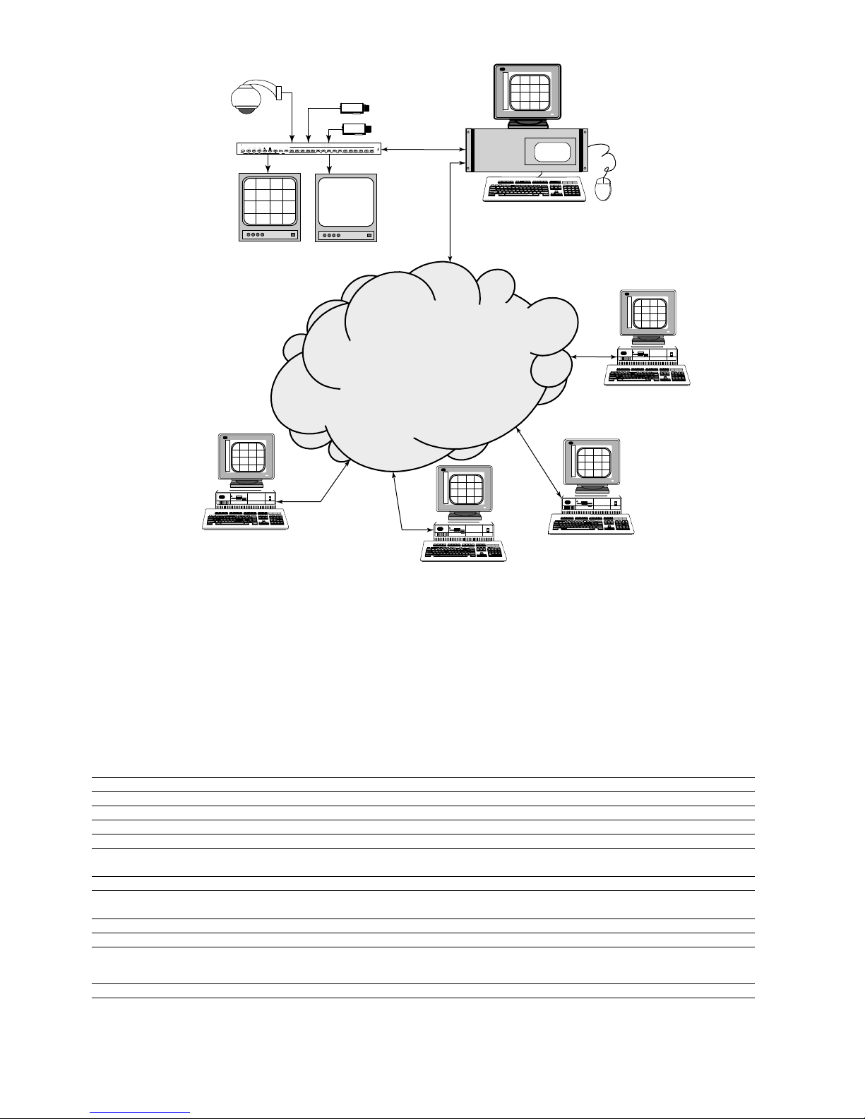
The Philips System4 Server provides a complete system solution for your security application. The system includes the
following components:
• System4 Server. PC unit digitally captures, compresses, and stores video supplied by the multiplexer.
• System4 Multiplexer. Multiplexes video and provides control functions for up to 32 cameras.
• System4 Server Configuration Software. Provides a user-friendly interface for system configuration and operation,
including daily scheduling, monitoring, and recording of system camera input.
• System4 Remote Viewer Software. Provides the added advantage of remote viewing of System4 video (live and
recorded) from another PC.
8
Figure 1 Typical System4 Server Application Diagram
Philips provides the System4 Server PC and Multiplexer package in the following configurations (key specifications are
outlined for each in the following chart):
PHILIPS
MODEL NO.
S4SVR S4SVRLP S4SVRSLP S4SVREP S4SVR2 S4SVR2EP
Electrical
Inputs with Automatic 16 16 16 16 32 32
Looping, BNC
Analog Monitor Outputs 2 2 2 2 4 4
Hard Drive Size (GB) 150 240 320 640 320 640
CD-RW N/A Included Included Included Included Included
Alarm Inputs 16 16 16 16 32 32
Alarm Outputs 2 2 2 2 4 4
Network Interface Included, RJ-45 Included, RJ-45 Included, RJ-45 Included, RJ-45 Included, RJ-45 Included, RJ-45
Card (Ethernet)
Remote Viewing Software Included Included Included Included Included Included
Rated Voltage 120/230 VAC, 120/230 VAC 120/230 VAC 120/230 VAC 120/230 VAC 120/230 VAC
50/60 Hz 50/60 Hz 50/60 Hz 50/60 Hz 50/60 Hz 50/60 Hz
Power at Rated Voltage 200 W 200 W 250 W 250 W 250 W 250 W
NTSC, EIA / PAL, CCIR Selectable Selectable Selectable Selectable Selectable Selectable
Mechanical
Dimensions W x D x H (mm) 483 x 457 x 178 483 x 457 x 178 483 x 457 x 178 483 x 457 x 356 483 x 457 x 178 483 x 457 x 356
Dimensions W x D x H (inch) 19 x 18 x 7 19 x 18 x 7 19 x 18 x 7 19 x 18 x 14 19 x 18 x 7 19 x 18 x 14
Weight 37 lbs 38 lbs 40 lbs 82 lbs 41 lbs 83 lbs
* Add one U high (1.75-inch) for 16-channel and two U high (3.5-inch) for 32-channel.
Each includes SVGA output via DB15.
PHILIPS
Video + RS-232
PHILIPS
Video Multiplexer
ALM
ACT
MMB
( %)
#
1 2 3 4 5 6 7 8 9 10 11 12 13 14 15 16
B
REC
VCR SEQ PLAY
System4 Multiplexer
PHILIPS
Mon A
(Optional)
Workstation Running
Remote Viewer
Software (Optional)
PHILIPS
Mon B
(Optional)
Ethernet
Connection
TCP/IP
Network
Workstation Running
Remote Viewer
Software (Optional)
System4 Server PC
Workstation Running
Remote Viewer
Software (Optional)
Workstation Running
Remote Viewer
Software (Optional)

9
SECTION 2: INSTALLING THE System4®SERVER
2.1 Installing the System4 Server PC Unit
The following information and diagrams guide you through installation of the System4 Server PC, multiplexer, and
peripheral components. The System4 Server PC is supplied in an enclosure designed to fit a standard EIA 19-inch
rack. If applicable, install the PC into the rack using appropriate mounting hardware (not supplied). The PC is also
supplied with 2 keys which fit its front panel lock.
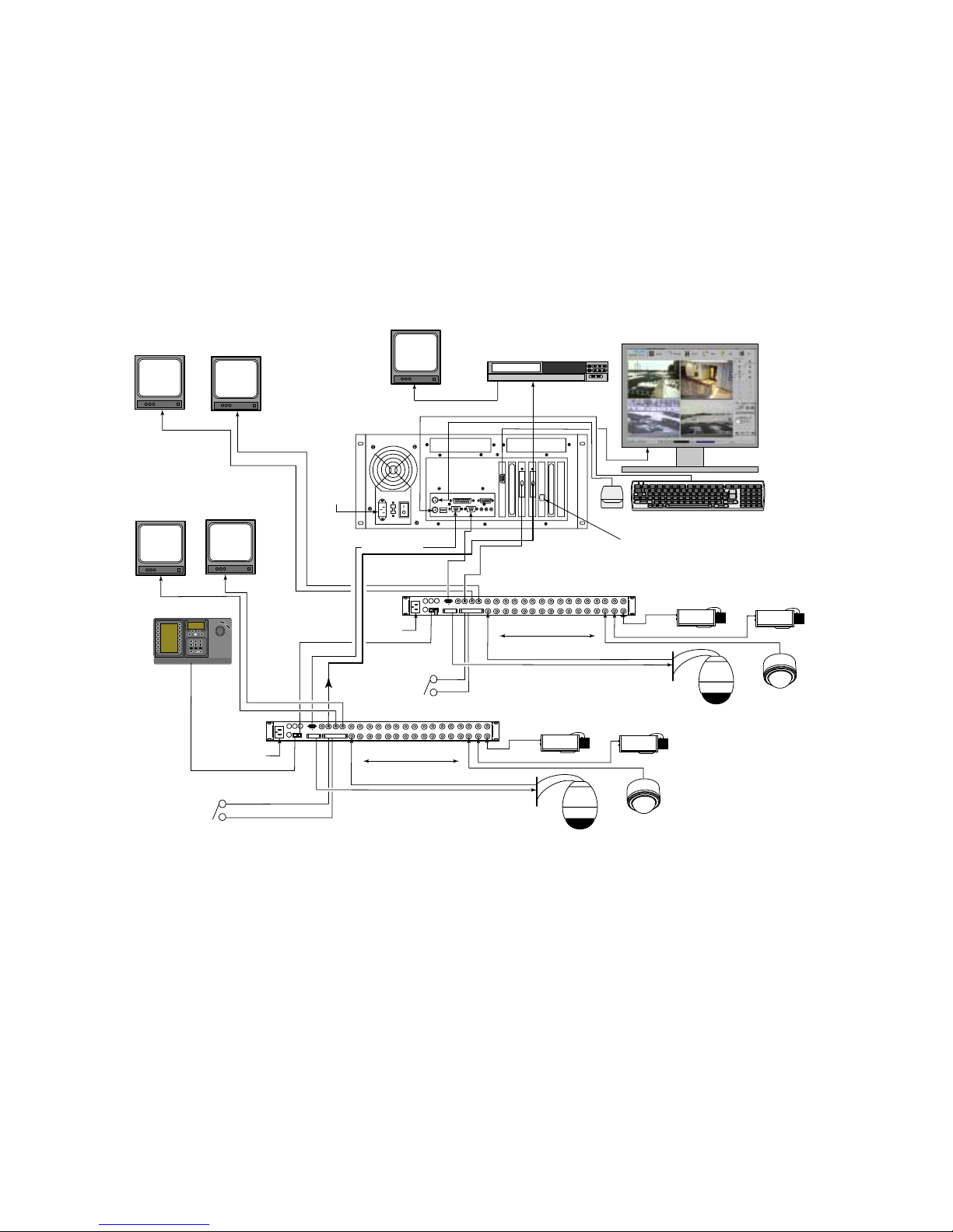
The System4 ’s multiplexer is a 16-input digital video multiplexer. When used with the System4 Server, the
multiplexer can output up to 30 unique images of video every second. The multiplexer delivers a time-base corrected
signal to the Server PC, which digitizes and stores the images on its internal hard drive. A second digital video
multiplexer can be added to the system configuration for a total of 32 inputs.
The System4 ’s multiplexer is supplied in an enclosure suitable for a desktop or rack mount installation. If the unit will
be rack mounted, remove the 4 rubber feet on the bottom of the unit, and attach the supplied racking ears to the side
of the enclosure. The unit can then be installed in a standard 19-inch EIA rack using appropriate hardware.
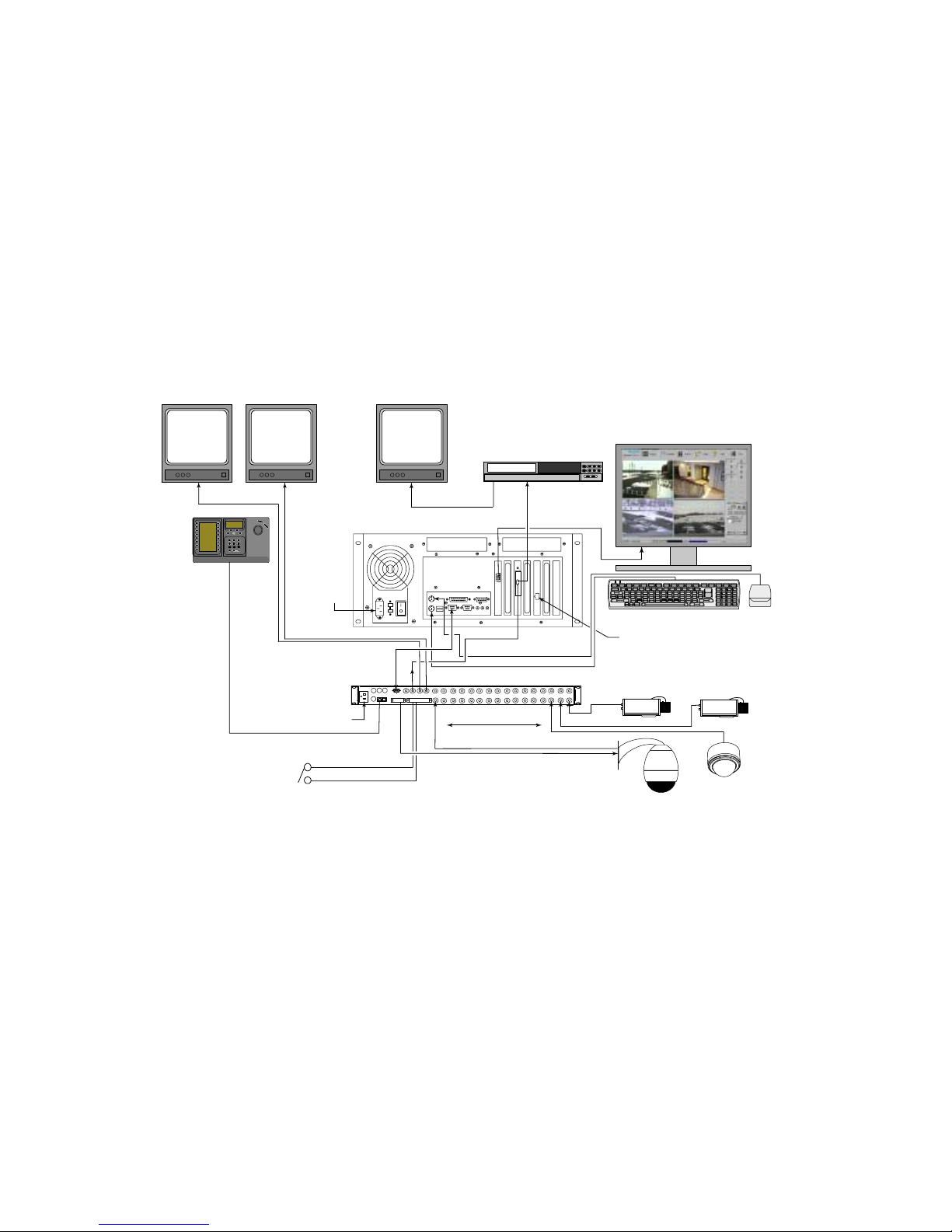
Use Figures 2 or 3 to complete the following installation instructions for the System4 Server PC and multiplexers.
1. Plug the keyboard cable into the keyboard connector and mouse cable into the mouse connector on the rear
panel of the System4 Server PC.
2. Attach the PC monitor (user-supplied) to the monitor connector of the System4 Server PC.
3. Plug the 25-pin male D-connector end of the System4 Interface cable into the DB-25 connector on the rear of
the System4 Server PC.
4. Plug the IN connector of the System4 Server Interface cable to the VCR OUT connector located on the rear
of the multiplexer.
5. Connect the OUT connector of the System4 Server Interface cable to an external video monitor, VCR, or
other analog device if you would like to view/record exported System4 Server video.
6. If images from the System4 Server will be viewed over a network using the Remote Viewer software, connect a
standard 100 BaseT Ethernet cable into the network card (J). See Figures A1 and A2 in Appendix A.
7. Connect the coax cables from the system video cameras to the video input connectors on the rear of the
multiplexer.
8. If using video loop-through connections, connect coax cables from the external devices to the appropriate
loop-through outputs on the rear of the multiplexer.
9. If the multiplexer will be used in a conventional stand-alone manner, you can connect its MON A and
MON B outputs to standard video monitors.
10. Connect one end of the 9-pin connector of the System4 Console Cable to Comm 1 port of the PC. Connect
the other end of the cable to the Console port of the multiplexer.
11. If applicable, refer to the manual supplied with the multiplexer to connect any control data and/or alarm
inputs/outputs to the multiplexer.
12. Plug the appropriate AC power cords into the power connectors of the System4 PC, the PC monitor, and the
multiplexer. Verify that the PC voltage selector switch located next to the AC line cord is set to the correct
position.
13. Plug the AC power cords of the PC, PC monitor, and multiplexer into an appropriate electrical outlet (the
multiplexer automatically functions when power is provided—there is no power switch).
14. To provide power to the System4 Server box, use the power switch on the rear panel. To turn on the Server
PC, use the power switch on the front panel.
10
VCR
IN
MON B
VCR
OUT
MON A
SDA
ALARM
CONSOLE
VCR IN
MON A
KEYBD
1 2
3 4 5 6 7 8 9 10
11 12
13 14
15 16
MON B
VCR OUT
POWER
LTC 2682/90
PHILIPS
PHILIPS
PHILIPS PHILIPS PHILIPS
VCR
PHILIPS
1
2
3
4
5
6
7
8
9
0
Shot
Mon
Prod
Clr
PHILIPS
System4
Mon B
(Optional)
System4
Mon A
(Note 1)
VCR Playback
Monitor
(Optional)
OUT Analog
Export Cable
(Optional Use)
Analog VCR
(Optional)
PC Monitor
(Not Supplied)
Ethernet
Network Port
(Optional Use)
Typical Fixed
Cameras
AC Ma in
Power
System4
Console Cable
System4
Keyboard
(Note 1)
AC Ma in
Power
Keyboard Cable
Typical System4
Alarm Input
(Optional)
Up to 16 System Cameras
Biphase Control Data
Video
Video
Video
Video
IN Cable
Mouse Cable
Keyboard Cable
AutoDome
®
Series
Controllable Camera
Dome
Camera
Note 1: These components are required for initial setup, but are optional for system operation.
Figure 2 Connection Details of the System4 Server PC, Multiplexer, and Accessories (16-channel)
11
VCR
IN
MON B
VCR
OUT
MON A
SDA
ALARM
CONSOLE
VCR IN MON A
KEYBD
1 2
3 4 5 6 7 8 9 10
11 12
13 14
15 16
MON B
VCR OUT
POWER
LTC 2682/90
PHILIPS
PHILIPS
PHILIPS
VCR
PHILIPS
Video
VCR
IN
MON B
VCR
OUT
MON A
SDA
ALARM
CONSOLE
VCR IN
MON A
KEYBD
1 2
3 4 5 6 7 8 9 10
11 12
13 14
15 16
MON B
VCR OUT
POWER
LTC 2682/90
PHILIPS
PHILIPS
1 2
3
4 5
6
7 8
9
0
Shot
MonProd
Clr
PHILIPS
PHILIPS
PHILIPS
PHILIPS
PHILIPS
Multiplexer #2
Multiplexer #1
Mouse Cable
Keyboard Cable
Note 1: These components are required for initial setup, but are optional for system operation.
System4
Mon B
(Optional)
System4
Mon A
(Optional)
System4
Mon B
(Optional)
System4
Mon B
(Note 1)
System4
Keyboard
(Note 1)
Keyboard
Cable
AC Ma in
Power
Typical System4
Alarm Input
(Optional)
Up to 16 System Cameras
AutoDome
®
Series
Controllable Camera
Dome
Camera
Video
Video
Video
AutoDome
®
Series
Controllable Camera
Dome
Camera
Video
Video
Video
Video
Typical Fixed
Cameras
Typical Fixed
Cameras
Up to 16 System Cameras
Typical System4
Alarm Input
(Optional)
Keyboard Cable
Biphase Control Data
AC Ma in
Power
AC Ma in
Power
System4
Console Cable
System4
Console Cable
IN Cable 1
IN Cable 2
Biphase Control Data
Ethernet
Network Port
(Optional Use)
VCR Playback
Monitor (Optional)
Analog VCR
(Optional)
OUT Analog
Export Cable
(Optional Use)
PC Monitor
(Not Supplied)
Figure 3 Connection Details of the System4 Server PC, Multiplexer, and Accessories (32-channel)
12
2.2 Initializing the Multiplexer
NOTE: The system will not be able to operate properly unless the next step is completed on the LTC 2682/90
multiplexer.
Before the multiplexer can be used with the System4 Server PC, you must configure it. This is easily done using the
LTC 2682/90 multiplexer’s (Version 3.03 or later) on-screen menus (if your multiplexer does not have firmware
Version 3.03 or later, it will need to be upgraded before it can be used with the System4 Server). With a standard
monitor connected to the MON A output of the System4 multiplexer, press ALT + menu (i.e., the ACT key) to enter
the on-screen menu. Once there, use front panel arrow controls to select the Advanced Menu. In the Advanced
Menu, scroll down the list until you reach the Remote System4 Setup option. By default, the setup option will always
appear as No. Select Yes, then confirm your choice. The system will briefly reset, and then it will be ready to accept
System4 Server commands.
2.3 Initializing the Configuration Software
When you turn on the System4 Server PC for the first time, it will automatically boot into the Windows®desktop
and run the configuration software. If the boot-up process stops at the Windows®log-in screen, verify/enter the user
name Administrator, leave password blank, and click OK to continue. From the desktop, you can also start the
configuration software program by double clicking the System4 Server icon.
When the Configuration Software program first begins to run, the System4 Remote Viewer software will
automatically start on the server and be minimized to the system tray by default. To view, press the Windows button
on the keyboard while the System4 is running, and double click the System4 icon in the system tray (status bar at
bottom of screen). When this window appears, you can minimize it if you will be using the Remote Viewer software
on a remote PC, or close it if you will not being using remote access.
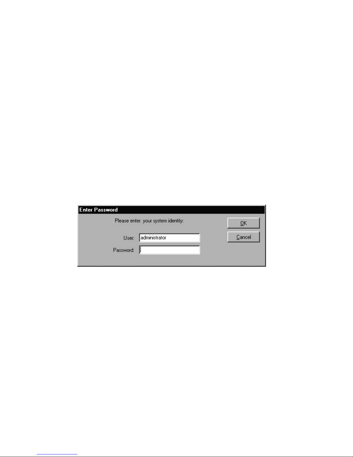
When you see the Configuration Software’s Enter Password window as shown below, enter administrator for User
and letmein for Password. The software then scans for connected cameras and opens up to the Monitor page.
NOTE: After initial system startup, be sure to change (customize) your user ID and password immediately. Refer to
Section 3 for complete instructions on how to accomplish this.
CAUTION: Your System4 Server PC has some of the same capabilities as a regular personal computer. However, it
is recommended that you DO NOT use your System4 Server PC for anything other than operating the System4
Server Configuration software. Changing software or hardware setups of the operating system could damage the
System4 Server’s intended functionality. Refer to the information on Security Features in the following section for
additional information.
13
SECTION 3: CONFIGURING THE System4 SERVER SOFTWARE
3.1 Introduction to the Configuration Software
The System4 Server Configuration Software provides a user-friendly interface that allows you to quickly and easily
monitor system operations and make changes in system functioning. The main configuration screen (shown below) is
divided into three areas:
• At the top of the configuration screen is a row of function buttons that allow you to access each function so that
you can easily set up or change configurations and schedules, perform video searches, or monitor camera inputs.
• The middle section of the configuration screen is reserved for the operation of the function selected from the top
row of buttons. This section may include view screens, camera buttons, list boxes, and more, depending on the
function selected.
• At the bottom of the configuration screen is a status bar that displays information about the current date and
time, the current status of each camera, disk usage, and whether the system is currently recording.
The Function Buttons
At the top left corner of the configuration main screen are the Philips logo and the six buttons, providing links to the
following pages:
• The top left corner where the Philips logo is located is actually a button to access the Log-on Screen. This screen
is used whenever it is necessary for a different user to log-in to the software.
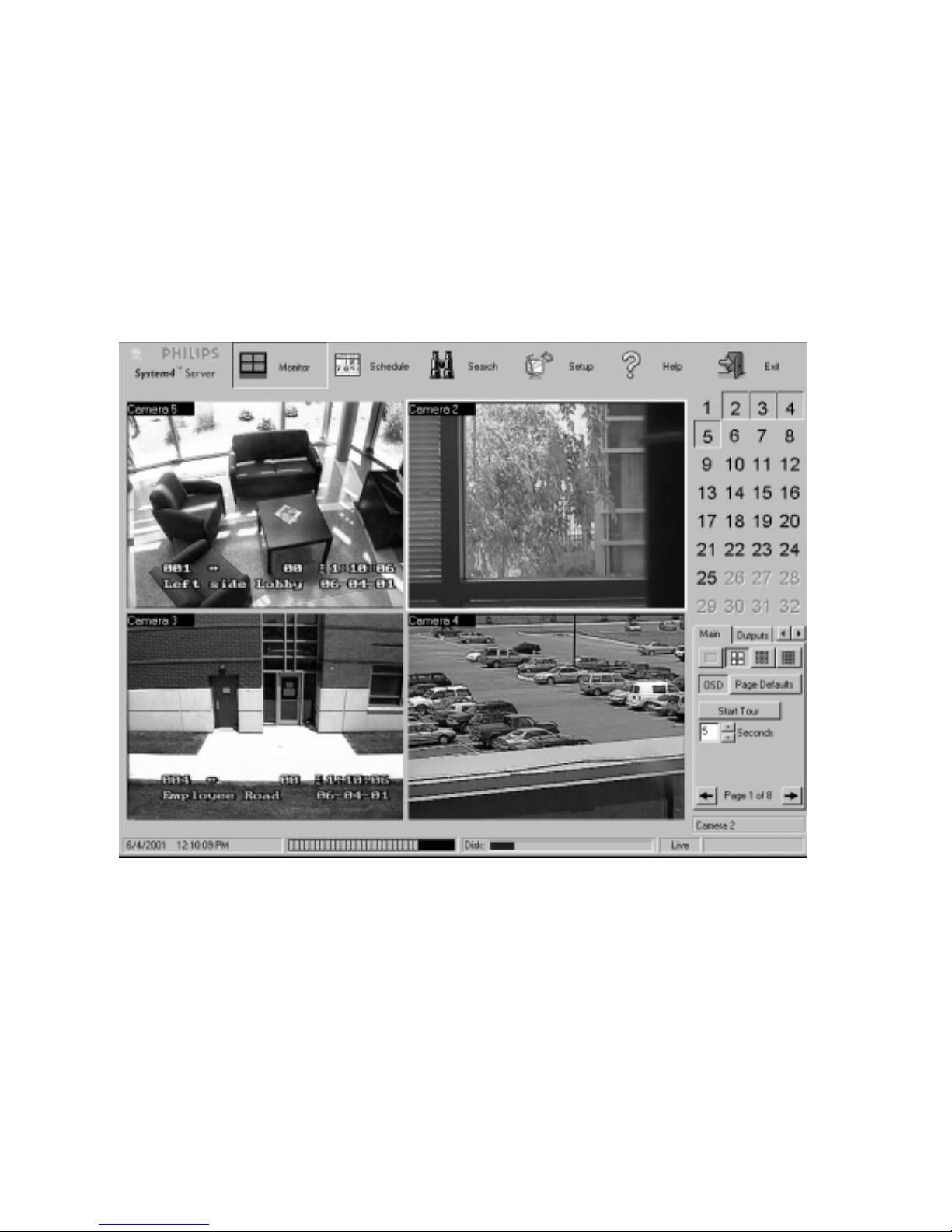
• The Monitor page is the primary way to monitor each connected camera. You can view live video from user-
selectable groups of cameras.
• The Schedule page allows you to control when each camera should start and stop recording video. Cameras can
easily be set individually or in groups. The Schedule page icon is grayed out when in the User mode.
• The Search page allows you to search for and view recorded video. Just enter a time period and whether you want
to search for all video or for events only.
14
• The Setup page is the master page for configuring disk usage procedures, hardware, system users, motion masks,
and more. The Setup page icon is grayed out when in the User mode.
• The Help button allows you to search for help or choose from a menu of help topics.
• The Exit button closes the Configuration program. The Exit icon is grayed out when in the User mode.
The Status Bar
The narrow status bar at the bottom of the Configuration screen contains the following information:
• The current date and time.
• The recording status of up to 32 camera inputs. Each input is represented by a box, with input (1) on the left and
the highest-numbered input on the right. If the camera detects a motion or alarm event while in Motion or Alarm
mode, the camera input boxes become a certain color that corresponds with the active recording mode, calling
attention to the event.
• The amount of disk space that is full.
• The status of system operation—either Live (not recording) or REC (recording).
3.2 Setting Up the Configuration Software for System Operation
Many important system functions can be configured through the Configuration main screen Setup function button.
The Setup page (which appears after clicking on the Setup button) includes 7 tabs, which are explained in order in
this section.
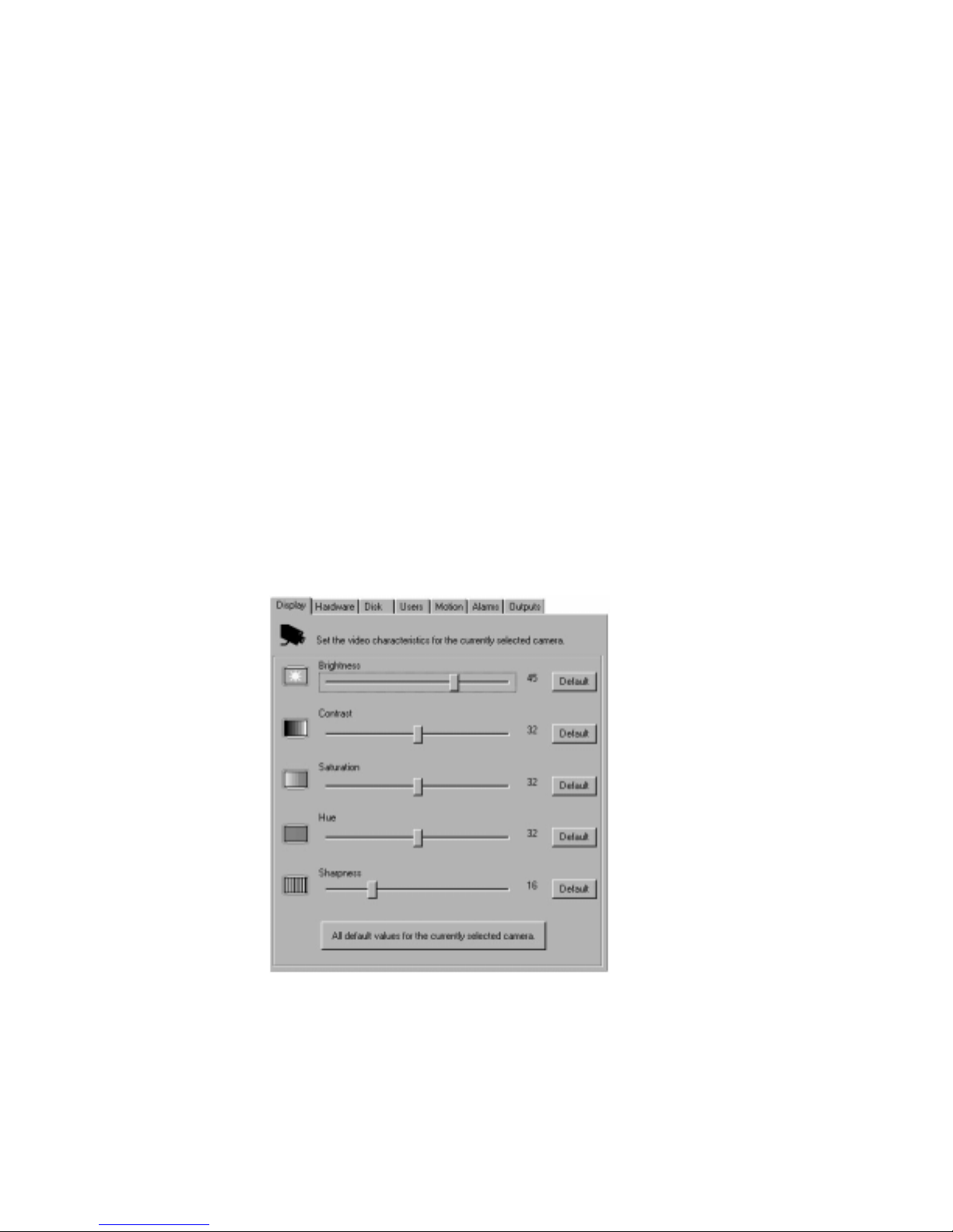
Setup Tab #1: Adjusting the Video Display
To adjust the brightness, contrast, saturation, hue, and sharpness of the displayed video, go to the Setup page and
choose the Display tab.
Working with the Display Tab Screen
1. First, select a camera input (number) button from the bottom of the screen. Then, adjust each setting by
moving the box on its slider bar to the right or left.
2. You can return to the default for each setting by clicking the Default button beside each slider bar, or you can
return to the default for all settings by clicking the All Default Values for the Currently Selected Camera
button.
15
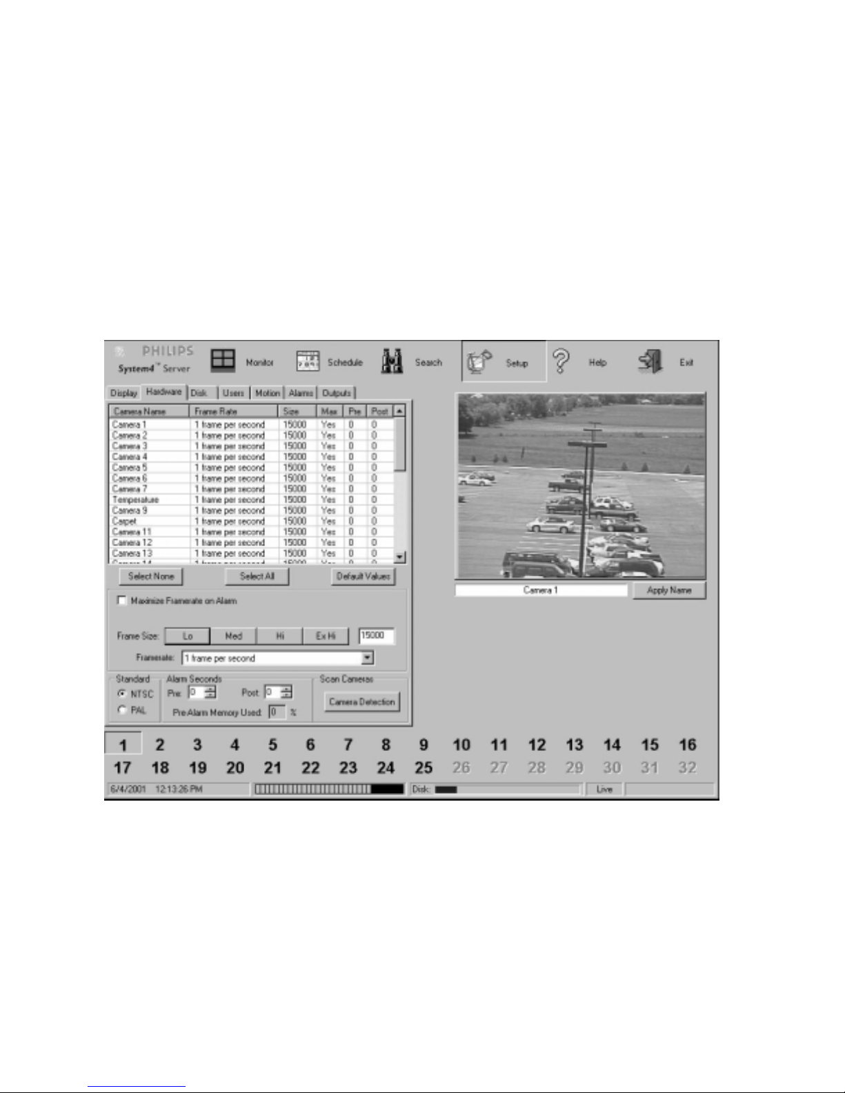
Setup Tab #2: Configuring Hardware
There are several ways to configure the system so that it does not fill the available disk space too quickly. The
procedures below can be executed from the Setup page Hardware tab as long as your are not in the Record mode.
• Compression value. The default setting compresses video to 15 KBytes per image. You can adjust this to any
value from 7 to 40 KBytes. Obviously, setting to a higher value will use disk space up quicker.
• Frame rate selection. The default setting records one frame every second. You can adjust the system to record at
its maximum potential rate or a wide range of rates—from ten frames per second to one frame every ten seconds.
The maximum number will depend on the number of cameras attached to your system.
• Setting prealarm and postalarm recording. This allows you to record events that occur immediately before and
after an alarm event. Prealarm recording temporarily stores a certain amount of video at all times in case an alarm
occurs. This requires a reserved amount of storage space. The amount of prealarm recording time you can
program is limited by the recording rate and image size specified for all cameras set for prealarm recording. The
amount of memory used is determined by the resolution and record rate selection for each camera. The Pre-
Alarm Memory Used field indicates the percentage of the prealarm memory that has already been assigned.
Working with the Hardware Tab Screen
1. Select one or more camera input from the list (or click Select All to choose all inputs).
2. Adjust the frame size by clicking Lo (7KB), Med (15KB), Hi (30KB), or Ex Hi (40KB) or adjusting the slider
bar to any intermediate value.
3. Choose a recording rate from the framerate drop-down list, and enter the number of prealarm and postalarm
seconds in the Alarm Seconds area on the screen. The frame size and rate are updated immediately when you
select them.
4. To reset an input to the default values, select the input and click Default Values.
5. To deselect camera inputs, click Select None.
 Loading...