

Page 1
SYSTEM
4822
872
30319
1.
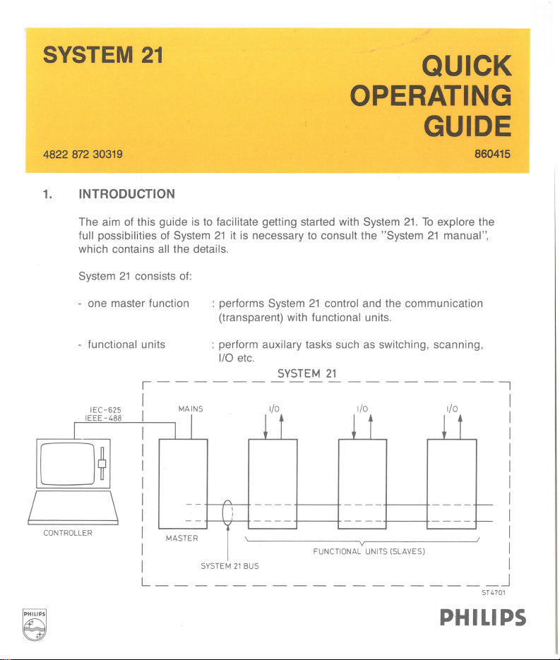
INTRODUCTION
21
QUICK
OPERATING
GUIDE
860415
The aim of this guide is
full possibilities of System
which contains all the details.
System
21
- one master function
functional units
-
IE
C-625
IE
EE
-488
I
0~
I
CONTROLLER
\
to
facilitate getting started with System
21
it
is necessary to consult the "System
consists of:
: performs System
(transparent) with
: perform
1/0
auxilary tasks such as switching, scanning,
etc.
,------------------,
I MAINS 1/0 1/0
I I
I I
I
~
21
functional units.
SYSTEM
t
control and the communication
21
~
t
21.
To
explore the
21
manual ",
1/0
~
t
I
I
I
I
I
I
MASTER
I
I
L
__
--
SYS
TEM
--------------
A
[ :
I
21
BUS
----
FUNCT
----
IONA
L UNITS (SLAVES)
---
r-r--
_j
ST4701
PHILIPS
I
I
I
I
I
I
I
I
I
I
Page 2
CONTENTS
1.
INTRODUCTION
2.
HOW
TO
INTERCONNECT THE UNITS
3.
ADDRESS SELECTION
4. ADDRESSING A MESSAGE
5.
COMMANDS
6.
READING
7. PROGRAMMING WITH IMMEDIATE EXECUTION
8.
PROGRAMMING WITH USE OF PRE-PROGRAMMING AND DIFFERENT
EXECUTION MODES
8.1.
PRE-PROGRAMMING
8.2
. LOADING THE BLOCK-MEMORY
8.3.
CLEARING THE BLOCK-MEMORY
8.4
. INITIATE COMMANDS
8.5. HOW
COMMANDS
8.
6.
HOW
8.
7.
PM-NUMBER ADDRESSED EXECUTION
8.
8.
BLOCK-OPERATION
8.9
. SCAN FUNCTION
DATA
FROM
SYSTEM
TO
EXECUTE THE PROGRAMMED
TO
PROGRAMME A TRIGGER
21
OR
INITIATED FUNCTIONAL
9. HOW
10
. HOW
11.
PROGRAMMING
12.
ANNEX
TO
TO
SEE
IF
UNITS ARE READY WITH THE PROGRAMMED
SEE
IF
UNITS
HAVE
DATA
AVAILABLE
FOR
THE EXPERTS
TASKS
Page 3
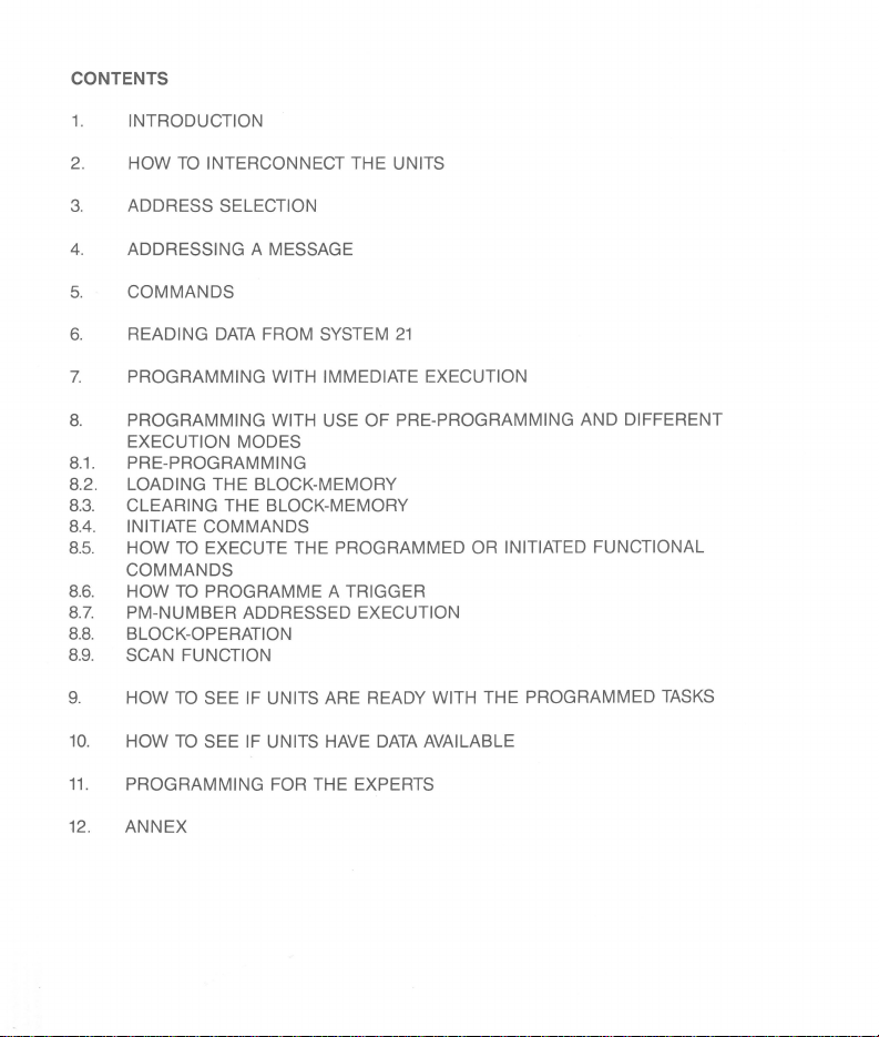
2.
HOW
TO
INTERCONNECT THE UNITS
by clipping the units
each other
Press here, while moving down
the upper unit with the feet
holes of the lower one.
release the button, by wich
Then
the feet hook into the
with cable-set PM2192
by using Rack-mount PM2193
If more distance between the units is required
the data-lines (data high twisted with data low) and the
the synchronization
on
holes.
lines.
top of
in
the
How
to
clip the units together
(.5 m up
to
maximum
OV-
lines may be used, not
150 m), only
ST4698
3
Page 4
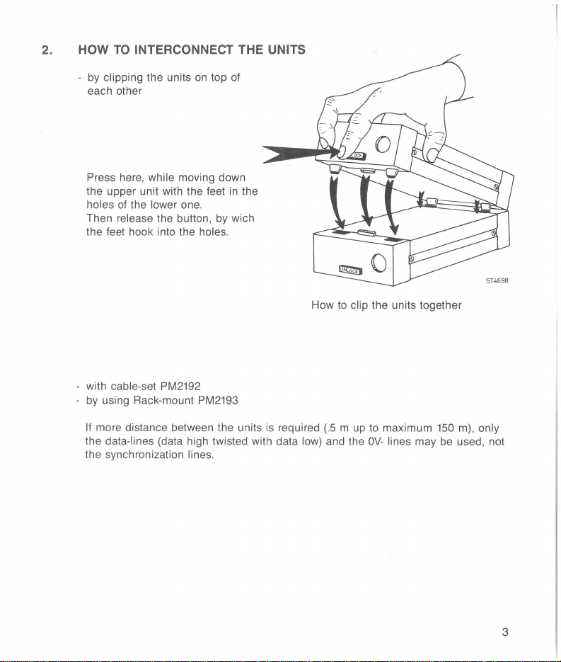
3.
ADDRESS SELECTION
IEEE/IEC-bus address of the Master Unit
(selectable addresses
are
10
...
19)
Warning: When an
even addresses is set, a
Service Request
will occur
after a power-on reset
(not
maskable).
ST4699
Example
Unit address of
of a
PM2101
Functional Units
with IEEEIIEC-device address
(consists of 2 fixed, type number dependent, and a third
20
Example of a PM2120 with unit address
4
203.
11
(default address)
variable digit)
ST4700
Page 5
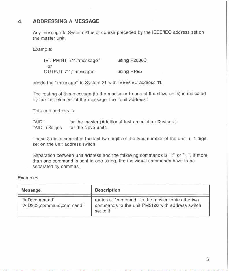
4. ADDRESSING A MESSAGE
Any message to System
the master unit.
Example:
IEC PRINT #11,"message"
or
OUTPUT
sends the "message"
The routing of this message (to the master or to one of the slave units) is indicated
by the first
This unit address is:
"AID"
"AID" +3digits for the slave units.
These 3 digits consist of the
set on the unit address switch.
Separation between unit address and the following commands is
than one command is sent in one string, the
separated by commas.
Examples:
Message
"AID;command"
''AID203;command,command'' commands to the unit
711;
element of the message, the "unit address".
21
is of course preceded by the IEEE/IEC address set on
using P2000C
"message"
to
System
for the master (Additional Instrumentation Devices).
last two digits of the type number of the unit + 1 digit
Description
routes a "
set to 3
using HP85
21
with IEEE/IEC address
individual commands have to be
command"
11.
";" or
to the master routes
PM2120 with address switch
",
the
".
If more
two
5
Page 6
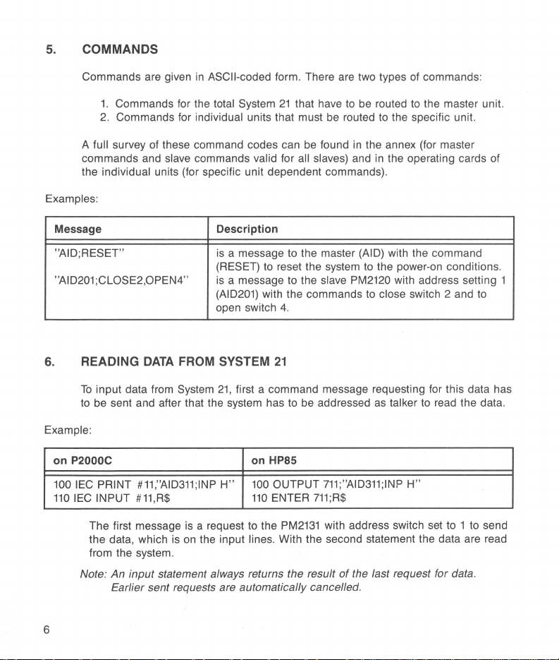
5.
COMMANDS
Commands are given
1.
Commands for the total System
2.
Commands for individual units that must be routed
full survey of these command codes can be found
A
commands and
the
individual units (for specific unit dependent commands).
Examples:
Message Description
"AID;RESET" is a message to the master (AID) with the command
"AI 0201 ;CLOSE2,0PEN4"
6.
READING
To
input data from System
to be sent and after that the system has
Example:
on P2000C on HP85
100
IEC
110
PRINT
IEC INPUT #11,R$
DATA
#11,"AID311;1NP
in
ASCII-coded form. There are two types of commands:
21
that have
slave commands valid for all slaves) and in the operating cards of
(RESET) to reset the system to the power-on conditions.
is
a message to the slave PM2120 with address setting 1
(AID201) with the commands
open switch 4.
FROM
SYSTEM
21,
H"
21
first a command message requesting for this data has
100
110
to
be addressed
OUTPUT
ENTER
to
be routed to the master unit.
in
the annex (for master
to
as
711;"AID311;1NP
711;R$
to
the specific unit.
close switch 2 and
talker to read the data.
H"
to
The first message is a request to the
the data, which is
from the system.
Note: An input statement always returns the result
Earlier sent requests are automatically cancelled.
on
the input lines. With the second statement the data are read
6
PM2131
with address switch set to 1
of
the last request for data.
to
send
Page 7
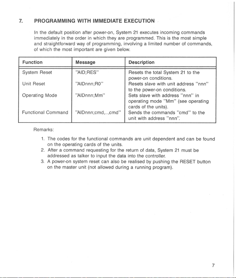
7.
PROGRAMMING WITH IMMEDIATE EXECUTION
In
the default position after power-on, System
immediately in the order
and straightforward way of programming, involving a limited number of commands ,
of which the most important are given
Function Message Description
System Reset "AID; RES"
Unit Reset
Operating Mode
Functional Command
Remarks :
1. The codes for the functional commands are unit dependent and can be found
on the operating cards of the units.
2. After a command requesting for the return of data,
addressed as
3. A power-on system reset can
on
the master unit (not allowed during a running program).
in
which they are programmed. This
"AIDnnn;RO"
"AIDnnn;Mm"
"AIDnnn;cmd,
talker to input the data into the controller.
..
,cmd"
also be realised
21
executes incoming commands
below.
Resets the total System
power-on conditions .
Resets slave with unit address "nnn"
to the power-on conditions.
Sets slave
operating mode
of
cards
Sends
unit with address
the units).
the commands
by
is
the most simple
with address
"Mm"
(see operating
"cmd"
"nnn
".
System
21
pushing the RESET button
21
to the
"nnn"
must be
in
to the
7
Page 8
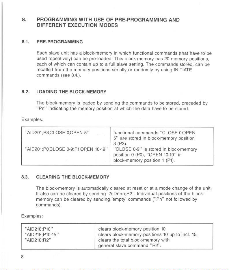
8.
PROGRAMMING WITH USE
DIFFERENT EXECUTION MODES
8.1. PRE-PROGRAMMING
OF
PRE-PROGRAMMING AND
Each slave unit has a block-memory
used repetitively) can
each of which can contain up
recalled from the memory positions serially or randomly by using INITIATE
commands (see
8.4.).
be
pre-loaded. This block-memory has 20 memory positions,
in
which functional commands (that have
to
a full slave setting. The commands stored, can be
8.2. LOADING THE BLOCK-MEMORY
The block-memory is loaded
"Pn"
indicating the memory position
Examples:
"AID201;P3,CLOSE
"AID201;PO,CLOSE 0-9;P1,0PEN
O,OPEN
by
sending the commands to
at
which the data have
5" functional commands "CLOSE
10-19
5"
are stored
3
(P3).
" "CLOSE 0-9" is stored
position
block-memory position 1
in
block-memory position
0
(PO),
"OPEN
8.3. CLEARING THE BLOCK-MEMORY
The block-memory
It also can be cleared
memory can be cleared
commands).
Examples:
is
automatically cleared
by
sending "AIDnnn;R2". Individual positions of the block-
by
sending 'empty' commands
at
reset or at a mode change of the unit.
("Pn"
be
stored, preceded by
to
be
stored.
O,OPEN
in
block-memory
10-19" in
(P1).
not followed by
to
be
"AID218;P10"
"AID218;P10-15"
"AID218;R2"
8
clears block-memory position
clears block-memory positions
clears the total block-memory with
general slave command "R2".
10.
10
up
to
incl.
15.
Page 9

8-4. INITIATE COMMANDS
With initiate commands, it is possible to recall the functional commands from the
block-memory. There are two possibilities:
Random recall: One can recall (initiate) any block-memory position. This is done
by
"I
n"
Serial recall: This is used with
where n (
example see
8.8.
=0 ...
19)
"Block
is the memory position to be initiated.
Operation". For a description with
Example of a random recall at unit address
"AID213;1
2"
The initiating of commands from the
programming.
It does not automatically conclude that these commands are also
213:
Block-memory position 2 is initiated.
block-memory is comparable with direct
executed. Execution only follows when execution conditions are met (see next part).
8.5- HOW
TO
EXECUTE THE PROGRAMMED OR INITIATED
FUNCTIONAL COMMANDS
the default position of the system, the execution of commands sent to the slaves
In
is immediately after receipt of the individual commands. This is the "Execute
mode.
To
Unconditional"
enable synchronisation of actions within a slave
between different slaves, two further execution modes are available:
- "Execute on
executed on the first following character
"Execute
next
trigger-impulse
X"
where programmed or initiated commands are simultaneously
on Trigger" where programmed
on
the System
"X"
received by the slave.
or
21
initiated commands are executed on
internal trigger line (see
8.6).
These execution modes of the individual slaves can be programmed by
following commands (example with unit address
312)
:
Command Description
"
AID312;E~U
"
AID312;E~X
"
AID312;E~T
"
"
"
Execute Unconditional mode
Execute on command "X" mode
Execute on Trigger mode (see
8.6)
or
the
9
Page 10

8.6. HOW
TO
PROGRAMME A TRIGGER
(impulse
on the trigger-line of the System
21
bus)
This can be done with
System
21
or
master command
IEEE-bus command GET (Group Execute Trigger)
"
AID;XCU~T
"
Examples:
"
on HP85
OUTPUT
TRIGGER
711
711
Using on P2000C
IEC
master command
IEEE command GET
PRINT
IEC
TRIGGER #
#11
,
"AID;XCU~T
11
8.7. PM-NUMBER ADDRESSED EXECUTION
When only a group of identical units have to receive an execute command this can
be done by the command
"Scan Function").
execution command
"AID;XCU nn " addressed to the master (see also 8.9.
"nn"
stands for the last two digits of the slaves type number. This
is
independent of execution mode setting.
Example:
"AID;
XCU
20"
All PM
2120
units will execute their received commands (also initiate
commands), independent
on
the execution modes selected.
8.8. BLOCK OPERATION
Block operation is the sequential execution of functional commands stored on
successive positions
from memory; see also
recall
I~B
[,n)". The section enclosed within ( ] is optional.
value 0 ..........
value "n", the default value will be
the
step by step by giving
selected,
or
a PM-number addressed execution command (see
at
the block-memory, always starting with position 0 (serial
8.4).
Block operation is initiated
19
indicating the last block-memory position to be executed. Omitting
"X"
or a trigger command, depending
19.
After that, execution can be performed
"n"
represents
by
command "AIDnnn;
on
the execution mode
8.7.).
Unconditional mode is not allowed for block operation. "Block operation, once
initiated, may
(commands with
only be followed by execution commands or request commands
"?")
. All other commands will cancel block operation.
10
;
"
AID;XCU~T
an
integer
The Execute
"
Page 11

Example with unit address 200:
"
AID200;E._)(,I~B,5,X
"
"AID200;X"
8.9. SCAN FUNCTION
Execute on
the first,
"X"
mode, initiate block operation and execute
block-memory position.
Execution of second position
position
5.
etc.
up
to
and including block
(Available only
The scan function is used for the
scan-cycle can be executed over channels of several units
in
some slave units)
sequential select of inputs, switches, channels. A
on
the condition that:
All units are of the same PM-number.
All units are set for the same operating mode (see the System
the operating cards of the
in
No unit is
The units have
Execute Unconditional mode (see
successive-addres.~s
The scan is initiated by the command "AID nnn;l s
slave units).
-
8.5)
.
with settings starting at
;;
,'
~h~te
'
rtnn
slave address. The execution is done with a number of execute commands or
triggers
equal
to
the number of channels
to
be scanned. Under the above
conditions a scan cycle will start with the lowest channel number of the unit with
to
address-switch set
initiated, may not
commands
will cancel the scan.
zero and continue along all channels and units. A scan , once
be
followed by other than execution commands. All other
Example:
"
AID200;E._)(
"AID201;E._)(,I~S"
"
AID202;E._)(,I~S
,
I~S
"
"
Initiate
a scan on PM2120 units with
addresses
200,
201
and 202.
Repetitively:
;X
CU
"AID
20"
Execute
to
all PM2120 units. The scan starts with
lowest channel of unit 200, and steps along all
channels
with the successive execute commands.
21
manual and
0.
r,ep~e.sents
the
11
Page 12

9.
HOW
TO
SEE IF UNITS ARE READY WITH THE PROGRAMMED TASKS
Default, the slaves pull the ready-line low as long as the programmed actions are
not finished. However each slave can be disabled to
pull the ready-line
low.
Command
"AID213;R~E"
"AID213;R~D"
The state of the ready-line can be read by the master command
Addressing System
"AID;RDY
"AID;RDY
10. HOW
Command
"AIDnnn;S
0"
1"
If more than one slave controls the
the different
ready·fsee System
are not
TO
SEE IF UNITS
The most appropriate
command:
?"
The response is "AIDnnn;S
availability (see
21
slaves..wtttr'1tf!Jnnn;S ?" to see which ones are ready and which ones
System
Description
ready-line control enable (default): unit
the ready-line low when not ready.
ready-line control disable: unit
the ready-line low (keeps ready passive true).
as
talker will give
ready-line is low: the unit(s) are not ready.
ready-line is high: the unit(s) are ready.
21
manual).
HAVE
way
to check for data availability at a unit is by the following
Description
ask for the status of unit with address "nnn".
"+
< 9 digits
21
manual).
as
response:
rea.4-~
DATA
AVAILABLE
>,
where digit number 5 represents data
trnor
213
213
will never pull
"AID;
ROY
user
can appry a status request to
will pull
?".
12
Page 13

11.
PROGRAMMING
System
21
offers
FOR
THE EXPERTS
an
extensive range of further facilities such as:
Service Request for several reasons, which can
Identification of
Configuration request
Status information of the master
Test
routines
A description of the use of above facilities is beyond the scope of this quick
operating guide .
study of the
System
21
master and slave units
to
see which unit addresses are present
as
• power fail
• address not present
• unit busy
• end of block or scan
• warning flags of slave units
• selected modes
• data available
To
explore all these possibilities of System 21, a more detailed
System
21
manual is required.
well the slaves such
be
masked separately
as:
13
Page 14

12. ANNEX
A summary of commands with descriptions is given below. The headings indicate
the functions
command
given for
except for the Group Execute Trigger and the Serial Poll commands where the
complete statements are given, because of the different command structure.
Defaults are given where applicable. The last column gives the section number
where the function is mentioned or
"Sys.M"
mentioned, it is referred
the command syntax, a space-character is necessary for command recognition.
Where a space
Default
IEEE/IEC address of
Unit address of slaves
Command level
0
IEEE/IEC-interface
Master
0
Slave
•
Function I Command
to
which the commands are related. The left column gives the
level
to
P2000C and HP85, the commands shall be filled
is mentioned,
addresses
which each command is applicable.
it
is referred to the System
to
the Operating Card of the slave. Where
is
given (for readability), it is optional.
PM2101
Statement
IEC
PRINT #11,"cmd" OUTPUT 711;"cmd"
IEC PRINT #11,"AID;cmd" OUTPUT 711;"AID;cmd"
IEC PRINt
Description Default See
handled
11
nnO
on
# 11,"AIDnnn;cmd" OUTPUT
in
this Quick Operating ·Guide. Where
21
Address switch
Address switch
are the last 2 digits of PM-number.
P2000C Statement on HP85
In
the following statements
in in
the place of
manual; where "Op.Crd" is
in
position
in
position
711;
"~"
"AIDnnn;cmd"
"cmd"
is given
1.
0.
nn
in
14
0
•
•
•
Reset
"RES"
"
RO"
"R1"
"R2"
RESet the complete System 7
to
the power-on conditions.
Reset unit
Reset unit
Clear the block memory
of the unit.
as
after power-on 7
as
after mode change .
Sys.M
8.3
Page 15

Function I Command Description Default
Operating mode
"Mn"
•
Functional command (slave command)
"CLOSE
•
Pre-programming
"Pn, cmd, ... , cmd" Functional commands
•
Block-memory clear memory
"Pn"
•
"Pn-m"
•
"R2"
•
Initiating
"In"
•
"I
•
"I~S"
•
Set trigger mode
"
TRG~R
0
0
"TRG~U"
~B
1"
[,n]"
"
Select operating mode n .
Example of a functional 7
command. These commands are
unit specific and are
in
the operating cards of the
different
"cmd, ... . ,
memory position n
Clears memory position n .
Clears
including m, where
O<=n<m<=19
Clears all memory positions.
Initiate block-memory position n
Initiate block
including memory position
Initiate a scan (see "scan
function).
TRiGger if Ready mode: enable
the trigger-commands GET and
"XCU T" only when the readyline
trigger command
line becomes true.
TRiGger Unconditional mode: "TRG
the trigger-commands GET
"
rate
slave units.
cmd"
memory position n up
is
true or delay the received
XCU
T" will unconditionally gene-
an
impulse
only handled
are stored
(n=0
...
.
operation, up
until the ready-
on
the trigger-line.
on
19).
to
n.
and
to
and
cleared
R"
See
7
8.1
8.2
8.3
8.3
8.3
8.1
8.4
8.4/
8.8
8.9
Sys.M
Sys.M
Sys.M
15
Page 16

Function I Command
execution mode
Set
"E~U"
•
"
E._)("
•
"E~T"
•
Trigger and execute commands
"X"
•
IEC TRIGGER #
0
TRIGGER
0
"
XCU~T
0
"XCU
0
Block operation
"
1~8
•
nn"
[,n]"
"
711
11
J
Description
Execute Unconditional mode.
This mode is not allowed for
block and scan operations.
Execute on command
Execute on trigger mode (low
impulse on the trigger-line).
eXecute (if in " E
Statements for P2000C and HP85
to generate a
cute Trigger). Generates a
on the System
enabled (see
eXeCUte the units by a pulse on
the System
enabled (see "Set trigger mode").
eXeCUte all units with "PM21nn"
numbers independent on the
execution mode of the units. This
command is
"I~S"
scan by more than one unit of the
same type number.
Initiate block operation,
and including memory position n.
This command is to be
by a repetitive execute command.
Each execute command executes
the present
position and initiates a next one.
The Execute
"
E~U
GET
"Set
21
useful when using
commands to perform a
block-memory
Unconditional mode
"
is not allowed here.
"X"
X"
mode).
(Group Exe-
21
trigger-line if
trigger mode"
trigger-line if
up
followed
mode.
pulse
to
Default
"E
).
U"
See
8.5
8.5
8.5
8.5
8.5
8.5
8.6
8.6
.6
8
8.7
8.8
8.8
.
16
Page 17

Function I Command
Scanning
"
I~S
•
•
D
D
D
•
D
D
D
0
•
D
D
•
"
Request f
"?"
Setting separators
"SPA
"BSP n"
Request Identity data
"
ID
"I?"
Request Configuration
"AID
Request Status
IEC
S=SPOLL
"
STA
"S ?"
Test
"
TSI~U
"
TSI
"T n"
un
n[,m]"
?"
?"
POLL #11,S
(711)
?"
"
" +CHR$(1-
Description
Initiates a scan. This command is
to
be
followed by a repetitive
execute command.
cute command the next channel,
switch or
Execute
"
E~U
ctional data Sys.M
Request for functiona l data. The 61
kind of data is determined
previous command.
cases the
n and m (optional) are the "SPR 10"
decimal values of the !SO-codes
to
m
n is the decimal value of the
code
n <
Identity of PM2101+HW and
rei.
Identity
Which unit addresses
See "Serial Poll".
]
Status
Status
70)
Test
Test
Perform test
I/O-line is selected. The
Unconditional mode
"
is not allowed here.
"?
be the record separator. n and
< 32 and #
to
be
the block separator.
32
and #
of
slave
data of System
data of slave ? Op.Crd
IEEE/IEC-interface.
IEEE/IEC-interface.
On
In
" is optiona
27
(ESC).
27
(ESC).
+HW
are
n.
each
many
l.
and
present?
21
?
by
SW
Default See
8.9
8.9
exe-
the Op.Crd
PM2101
. S
..
"
PM2101
PM2101
Sys.M
PM2101
Op.Crd
Sys.M
Sys.M
PM2101
PM2101
Sys.M
PM2101
PM2101
ISO
- "BSP 10"
SW
rei.
=
LF
=
LF
"
PM2101
"
PM21
... S .. "
17
Page 18

Function I Command
Service Request masking
"MSR
D
n"
Description
Mask Service Request with
decimal value
n=
0 ....
511
Default
"MSR
0"
See
PM2101
0
Mask-values:
decimal
value
"MSK"+
digits:
values may be added to enable
more conditions to generate
Service Request when:
enable
256
128
16
<digits>
PM2101
A System
PM2101
Mask System
is no longer BUSY
21
received
(maximum 9 digits). A zero digit
disables the corresponding event
to generate a
"1"
A slave had a power fail,
received a power-on reset or
an
received
illegal code or illegal
sequence.
"
2"
An addressed module is not
present.
"3"
All units became ready
performing the programmed
actions.
''4''
All units are ready with the
received data and may receive
new data.
"5"
"6"
A unit has data available.
All units are ready with the
block or scan.
"7" A unit has a warning.
"8" The ready-line became high
(ready true)
"9"
A trigger-pulse was captured
the trigger-line.
event occurred
an
illegal code
21
events
Service Request.
SRQ.
on
"MSK
"0
"
"0"
"0"
"0"
"0"
"
0"
"0"
"0"
"0"
0"
Sys.M
18
Page 19

Function I Command Description Default See
Poll
Serial
D
IEC
POLL
#11
D
•
•
0
0
0
•
0
•
•
0
0
0
•
0
0
Additional
"BBS
"
S=SPOLL
Ready-line
"
R~D
"
"
R~E
"
"
ROY?
"
Sequential
"
SEQ~ON
"
SEQ~OFF
Request
"M ?"
"
TAG?
"
"E
?"
"R ?"
"MSK ?"
"
SEQ?
"
"DMP ?"
"D ?"
?"
DAV
?"
,S Statement to perform Serial Poll
(711)
control/read
execution
"
"
settings I modes
requests;
on
P2000C; status byte returned
inS
.
Statement
on
inS.
Ready-line control disable.
Ready-line control enable.
Logic state
Sequential execution. "SEQ ON"
Parallel execution possible .
Actual
Trigger mode of master ? "
Execution mode of slave ?
Ready-line control mode ? "R E"
System
SEQuential
Dump data
Dump data of slave ?
warning:
Which unit addresses are Busy
with a Block or a Scan ?
Which unit addresses have
Available?
to
HP85; status byte returned
perform Serial Poll
of
the ready-line ? "
operating mode
21
event mask ? "MSK 000000000"
execution mode ?
of
master ?
slow
responses
of
slave ?
"R E"
ROY
TRG
"E U"
"
SEQ ON"
"MSK 000000000,
TAG R,SEQ ON"
"M.,E U, R E"+
< functional
DAta
~
1"
R"
PM2101
PM2101
PM2101
9
9
9
9
Sys
.M
Sys.M
Sys.M
Sys
.M
settings>
Sys.M
10
19
Page 20

DATA-
AND STATUS-REQUEST COMMANDS WITH RESPONSES
A summary of all request commands for output- and status-data with the
corresponding responses is given
to
which each command is applicable.
and HP85, the commands shall be filled
command
data.
"AID;", those from the slaves are preceded by "AID nnn; ".
Command level
D
IEEEIIEC-interface
Master
0
Slave
•
shall
be
All responses, mentioned
followed by
Statement on P2000C
IEC
IEC
IEC PRINT
below. The left column gives the command level
In
the followi
an
in
PRINT #11,''
PRINT #11,''
in in
INPUT/ENTER command
the summary, from the master are preceded by
cmd"
AID;cmd"
# 11,''AIDnnn;cmd" OUTPUT
ng
the place of "cmd". The request
statements given for P2000C
Statement on HP85
OUTPUT
OUTPUT
I "nnn" represents the unit address of the addressed slave
Requested data Command data Description
Functional data
•
Response:
0 Data available
Response: "
Example: "DAV
Ready-line
0
0
Response:
Busy Block or Scan
Response:
Example:
Response data
"?"
< slave data> These data are specified
DAV
?"
"
DAV
" + < addresses> List of addresses of all units which
310,311,312
"ROY?"
"
ROY
0"
"ROY 1"
"BBS ?"
"BBS" + < addresses>
210,211,212
"BBS
Request for functional data.
operating cards of the units.
Request for the unit addresses
which have DAta
,''
have data available.
Warning: The master will poll all
PM-numbers,
few seconds maximum.
Logic state of the ready-line ?
if ready-line is low (ready false)
if ready-line is high (ready true).
Which units are Busy with
Block or a Scan ?
a
all units which are Busy
List of
,'' with a Block or a Scan.
to
read the requested
711
,''
cmd"
711
,''
AID;cmd "
711
,''
A1Dnnn
in
Available.
which may take a
;cmd "
the
20
Page 21

Requested data Command data Description
~
•
0
•
•
0
!ingmode
Response:
Example:
Trigger-mode
Response:
Execution mode
Response:
Ready-line
control mode
Response:
Event mask
Response:
digits:
Response data
"M
?"
"Mn"
"M2"
"
TAG?"
"TAG
R"
"TAG
U"
"E
?"
"E
U"
"
EX"
"E
T"
"R
?"
"R E"
"R D"
"MSK ?"
"MSK "+ <9 digits>
"1"
"2"
"3"
"4"
"5"
"6"
"
7"
"8"
"9"
Ask current operating mode .
Mode n
Selected
Read current trigger-mode.
Trigger if ready mode.
Trigger unconditional mode.
Ask current execution mode.
Execute Unconditional mode.
Execute
Execute
Ask ready-line control mode.
Ready-line control Enabled.
Ready-line control Disabled.
Read current System
mask. Indicates which events set
the abnormal bit (AB) together with
the EF3 bit
A slave had a power fail, received
a power-on reset or received
illegal code or illegal sequence.
An
present.
All units became ready performing
the programmed actions.
All units are ready with the
received data and may receive
new data.
A unit has data available.
All units are ready with the block
or scan.
A unit has a warning.
The ready-line became high (ready
true).
A trigger-pulse was captured
the trigger-line.
is
selected.
operating mode
on
"X" mode.
on
trigger mode.
in
the Serial Poll byte.
addressed module is not
21
2.
event
an
on
21
Page 22

Requested data Command data Description
0 Identity
Response:
Example: "PM21010 S0
Identity
•
Respons
Example: "
L Configuration
0
0
•
Response:
Example: "
Sequential mode
Response:
Dump data of
master
Response:
DumR data of slave
Response: < operating mode> +
Response data
"
ID
?"
"PM2101h Snn"
1"
"I?"
"PM21nnh Smm" PM21nn hardware version " h" with
e:
PM21310
"
AID?
"
AID
< unit adresse
AID
"
SEQ?
"SEQ ON" Sequential mode on.
"SEQ OFF" Sequential mode off.
"DMP
the master.
< event mask> +
<trigger mode > +
<sequential
"D ?" Ask tor the programming data of
< execution mode> +
<ready-line mode> +
<funct.
S01
"
"
" +
200,
s>
301
,"
" Sequential execution
?"
mode>
settings >
Ask tor the IDentity of the
PM2101
software
PM2101
with sotware release
Ask tor the Identity
functional unit.
software
PM2131
with software release 01.
Which addresses present?
List of all available addresses
PM2120
PM2130 with unit address 1 are
present.
Warning: The master will poll all
PM-numbers,
seconds maximum.
Ask tor the programming data of
See above.
the
Can be used to reprogram the
unit with the same settings.
hardware version "h
release "
hardware version 0,
release "mm".
hardware version 0
with unit address 0, and
slave.
nn"
01.
of
which may take a few
ON
PM2101
.
",
with
the addressed
or
OFF ?
22
Page 23

Requested data
System
0
21
status
Response:
digits:
Example:
Command data
Response data
"
STA
?"
"STA" +
<9
"1" Master detected a power-on reset.
"
2"
"3" A unit is busy.
"
4"
digits>
"5"
"6" One
Description
Request system
The addressed unit was not
present.
A unit is not ready with the
received data.
A unit has data available and
should be read.
or
more units are busy with a
block or scan.
21
STAtus.
"7'' A unit has a warning.
"8"
"9"
STA
"
103056700"
The master detected the readyline high; ready is true (available
on PM
2101
on all masters).
The master captured a trigger pulse
on the trigger-line (available on
PM2101
masters).
Digits
cleared when read.
A digit which is
related message is not true.
the
master; not available
master; not available on all
"1
", "2",
"8" and "9" are
"0", indicates that
23
Page 24

Requested data
Slave-status
•
Response:
Digits:
(flags)
Command data
Response data
"S ?"
"S "+
<9
digits>
"1" Power-on reset or power fail.
"2"
"3"
"4"
"5"
"6" Busy with a block or a scan.
"7"
"8" Warning 2 specified per unit
"9"
Description
Ask for the status of the unit.
A non-zero digit represents one of
the messages given
digit means that the message
belonging
digit
Alarm
This event
the
but this masks all System
events.
Illegal
error).
Functional commands are
cancelled because of
command sequence.
Data available; unit should
Warning 1 J
Warning 3
The message -
"5" and "6
"S ?" with the next IEEE/IEC-bus
input.
to
in
the string, is
(not applicable
can
"MSR ''command (" MSR
code received (programming
",
below. A zero
the position of the
not
true.
to
only
flags, except digits
are
all units).
be
masked by
an
illegal
reset after
21
be
128
read.
")
24
 Loading...