

Page 1
I
N
1
I
N
2
I
N
3
I
N
4
S
E
L
E
C
T
M
O
D
E
A
U
T
O
M
A
N
U
A
L
R
-
A
U
D
I
O
-
L
Y
G
V
I
D
E
O
P
b
B
P
r
R
I
N
P
U
T
4
S
-
V
I
D
E
O
EN User manual 3
SP Manual de utilizador 5
SWS2821T/17
FR
Manuel d'utilisateur 8
1
Page 2
EN
Introduction
Introduction
Congratulations on your purchase of PHILIPS Multi-video input
A/V switcher. Your A/V switcher is designed to accept up to 4
signals from any AV equipment and deliver them to a TV or a
Home Theater System. The switcher accepts video input signals
from component, s-video or composite video sources and audio
input signals from a stereo audio source to provide a single
audio/video output to your TV. NOTE:The switcher can convert an s-video signal to composite video, and vice versa. But it
can not convert component video signals.The switcher is
designed to operate either in Manual mode or Automatic mode.
Parts Required
You will need the following items, not supplied with your AV
switcher.
Stereo audio cable
Component video cable
S-Video cable OR
Composite Video cables
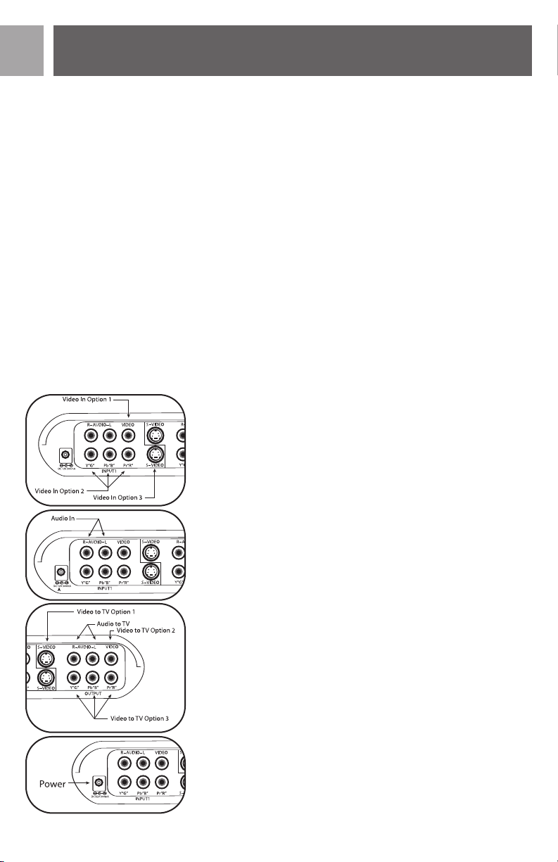
Connection
Follow these steps to connect your AV Switcher.
• Connect one end of a video cable plug (S-Video, composite
video or component video) to the output jack(s) of your
video source then connect the other end of a video cable
plug to any one of the input jacks on your AV switcher.
OR
• Connect the stereo audio cable plugs between the audio output jacks of an audio source and the audio input jacks (red &
white) on your AV switcher.
• Connect a video and an audio cable between the video and
audio output jacks of the AV switcher and the video and
audio input jacks of your TV.
• Connect DC power plug on the back of the unit and plug the
AC/DC power adapter to an 120VAC outlet.
2-pin
Note: You must use matching cables for input and output connections in order for the unit to work properly. (for example, if
you use a component video cable as an input, you must use a
component video cable for output.)
2
Page 3
Operation
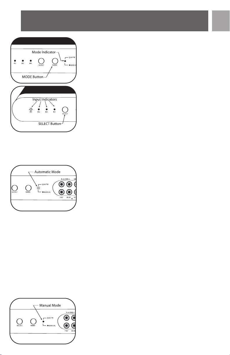
MODE Button
The MODE button toggles between the automatic mode and the
manual mode. In the automatic mode, the red LED is normally
ON. In the manual mode, the red LED is OFF. By default, the
AV switcher will be in the automatic mode. To change from an
automatic mode to manual mode, simply press the MODE button once, the red LED will turn OFF.
SELECT Button
The SELECT button is available only when the AV switcher is in
the manual mode. By default, the AV switcher selects input-1
when switching from automatic mode to manual mode.To select
a desired input simply press the SELECT button and the AV
switcher changes inputs from Input-1 to Input- 2 and IN2 LED
will be lit. Press the SELECT button again, Input-3 will be selected and IN3 LED will be lit. Pressing the SELECT button again
will select next input which is Input-4 and IN4 LED will be lit.
The input selection is cyclic.
Automatic Mode Operation
When the MODE LED is ON, the unit is in automatic mode.
The unit automatically searches for all video inputs to find the
last active video signal. The unit is designed to select the last
active video input automatically. For Example:
EN
→
→
→
→
→
→
IN2
IN3
→
→
If a user selected video inputs in this sequence IN1
→
→
IN3
IN4, at this time, the video output will be from IN4
(front Input). If there is no video signal for IN4 input, the unit
automatically switches to next previous input source. (in this
case, it will be IN3).
If the user selects video input in this sequence: IN1
→
→
IN4
IN2, at this time, the video output will be IN2. If there is
no video signal for IN2 input, the unit will switch to next previous video input source (in this case, it will be IN4).
Note: When the switcher is in automatic mode and the user
decides to change to Manual mode, the output of this unit will
be routed to the last active input.
Manual Mode Operation
When the user presses the MODE button, the unit enters into
the LED IN1
The mode indicating LED will g
ual mode
man
will be lit.
user presses the SELECT button, the LED IN2 will be lit and
LED IN1 will go off. The output of this box will now be routed
.
The output of this bo
x will be routed to IN1. If the
o off,
3
Page 4

EN
Operation
to input 2. This procedure is cyclic, user can manually change
inputs from IN1 to IN4 in sequence.
Note:When the unit is being used in the Manual mode operation and the user changes to Automatic mode, the operation will
begin as outlined in the Automatic Mode Operation.
Technical Support
Technical Support
For Technical Support send an email with the model number of
the product and a detailed description of your problem to:
Email: accessorysupport@philips.com
Warranty
Limited Lifetime Warranty
The manufacturer warrants that this product shall be free from
defects in material, workmanship and assembly,under normal use,
in accordance with the specifications and warnings, for as long as
you own this product.This warranty extends only to the original
purchaser of the product, and is not transferable. Defective products, together with the dated proof of purchase, must be returned
to the place of purchase for repair or replacement. THERE ARE
NO OTHER EXPRESS WARRANTIES. Incidental and consequential damages are disclaimed where permitted by law. This warranty gives you specific legal rights,and you may also have other rights
which vary from state to state.
©2006
Accessories Ser
Philips Accessories and Computer Peripherals,
Ledgewood, NJ 07852 USA
Quality assured in USA
Printed in China
4
vice Center
Page 5

Introduccción
Introducción
Felicitaciones por su compra del selector de entrada A/V PHILIPS
Multi-video. Su selector A/V ha sido diseñado para admitir hasta 4
señales de cualquier equipo AV (audio/video) y enviarlos a un TV o
un sistema de “cine en casa” (Home Theater). El selector admite la
entrada de señales de video desde fuentes de video de un componente, S-video o combinado, y la entrada de señales de audio de una
fuente de audio estéreo que suministra una salida simple de
audio/video a su TV.
NOTA: El selector puede convertir una señal de S-video a una señal
de video combinada y viceversa, pero no puede convertir las señales
de video de un componente. El selector ha sido diseñado para
operar ya sea en modo manual o en modo automático.
Accesorios Necesarios
Se requieren los siguientes artículos no suministrados con el selector AV.
Cable de audio estéreo
Cable de componente de video O
Cable de S-video O
Cables de video combinados
Conexión
Seguir los siguientes pasos para conectar su selector AV.
• Conectar el terminal de un cable de video (S-video, video combinado o componente de video) al (a los) conector(es) de la fuente
de video y luego conectar el otro extremo de un cable de video a
cualquiera de los conectores de entrada en su selector AV.
SP
• Enchufar los conectores del cable de audio estéreo entre la salida
de audio de una fuente de audio y los conectores de entrada de
audio (rojo & blanco) en el selector AV.
• Conectar un cable de video y un cable de audio entre los conectores de video y de audio del selector de AV y los conectores de
entrada de video y audio de su TV.
• Conectar el enchufe de corriente DC al dorso de la unidad y
enchufar el adaptador de corriente AC/DC de 2 clavijas a un
enchufe de corriente de 120VAC.
Nota: Debe utilizar cables que coincidan para las conexiones de entrada y salida para que la unidad funcione en f
lo, si utiliza un cable de video de componente como una entrada, debe
utilizar un cable de componente de video para la salida.)
orma adecuada.
(por ejemp
-
5
Page 6

SP
Operacion
Operacion
Botón MODE
El botón MODE permite alternar entre el modo automático y el
modo manual. En el modo automático, el indicador LED rojo, normalmente está encendido (ON). En el modo manual, el indicador
LED rojo esta apagado (OFF). Por defecto el selector AV se encuentra en el modo automático. Para cambiar del modo automático al
modo manual, simplemente presionar el botón MODE una vez, el
LED rojo se apagará.
Botón SELECT
El botón SELECT está disponible únicamente cuando el selector AV
se encuentra en el modo manual. Por defecto, el selector AV selecciona Entrada-1 al cambiar del modo automático al modo manual.
Para seleccionar la entrada deseada, simplemente presionar el botón
SELECT y el selector AV cambia las entradas desde Entrada-1 a
Entrada-2 y el indicador LED IN2 se encenderá. Presionar el botón
SELECT nuevamente, se selecciona Entrada-3 y el indicador LED IN3
se encenderá. Al presionar el botón SELECT nuevamente, se selecciona la siguiente entrada que es la Entrada-4 y se enciende el indicador LED IN4.
Esta selección de entrada es cíclica.
Modo de Operacón Automática
Cuando el MODO LED está en ON (encendido), la unidad se
encuentra en el modo automático. La unidad automáticamente
explora todas las entradas de video en busca de la última señal de
video activa. La unidad ha sido diseñada para seleccionar la última
señal activa de entrada de video.
Por ejemplo:
Si un usuario ha seleccionado las entradas de video en la secuencia
→
→
→
IN2
IN1
IN4 (entrada frontal).
Si no hay señales de video para la entrada IN4 la unidad automáticamente cambia a la siguiente fuente de entrada previa (en este caso
será IN3).
Si el usuario selecciona la entrada de video en esta secuencia: IN1
→
→
IN3
IN4
hay señal de video para la entrada IN2 la unidad cambia a la siguiente
fuente de entrada de video previa (en este caso será IN4).
Cuando el selector se encuentra en el modo automático y el
Nota:
usuario decide cambiar al modo Manual, la salida de esta unidad se
canaliza a la última entrada activa previa.
6
→
→
→
IN3
IN4, esta vez la salida de video será desde
→
→
IN2, en este caso la salida de video será IN2. Si no
→
→
Page 7

Operacion
Modo de Operacion Manual
Cuando el usuario presiona el botón de MODO, la unidad ingresa al
modo de operación manual. El indicador de modo LED se apaga, se
enciende LED INI. La salida de esta caja se canaliza hacia INI. Si el
usuario presiona el botón SELECT, se enciende LED IN2 y se apaga
LED INI.
La salida de esta caja se canaliza a la salida 2. Este procedimiento es
cíclico. El usuario puede cambiar manualmente las entradas desde INI
a IN4 secuencialmente.
Nota: Cuando la unidad está en uso en el modo de operación
Manual y el usuario cambia al modo de operación Automático, la
operación comenzará según se indica en Modo de Operación
Automática.
Asistencia Técnica
Correo electrónico:
accessorysupport@philips.com
Garantía
SP
Garantía limitada de por vida
El fabricante garantiza que este producto carece de defectos de material,
manufactura o armado, bajo uso normal y de acuerdo con las especificaciones y advertencias, durante el tiempo que éste sea de su propiedad. Esta
garantía cubre únicamente al comprador original del producto y no es
erible. Los productos defectuosos deben ser de
transf
vendedor, junto con la prueba de compra que indique la fecha, para su
reparación o reposición. NO EXISTEN OTRAS GARANTÍAS
EXPLÍCITAS. No se aceptan reclamos por daños incidentales e indirectos,
de acuerdo a lo permitido por la ley. Esta garantía le otorga derechos
legales específicos, y usted puede tener otros derechos que pueden variar
de estado a estado.
©2006
Accesorios
vicio de
o de Ser
Centr
Philips
Accessories and Computer P
Ledgewood, NJ 07852 USA
Calidad comprobada en los EE.UU.
Imprimido en China
eripherals,
vueltos al comercio
7
Page 8

FR
Introduction
Nos félicitations à l’occasion de l’achat du commutateur A/V
multi-vidéo de PHILIPS.Votre commutateur A/V est conçu pour
accepter 4 signaux en provenance de tout appareil AV afin de les
envoyer vers votre maison ou système home-cinéma. Le commutateur accepte les signaux d’entrée composant, s-vidéo ou composite vidéo ainsi que les signaux d’entrée audio stéréo afin de
permettre une seule sortie audio/vidéo à votre téléviseur.
REMARQUE : Le commutateur peut convertir un signal s-vidéo
en composite vidéo et vice-versa. Par contre, il ne peut pas convertir les signaux vidéo composant. Le commutateur est conçu
pour fonctionner en mode manuel ou en mode automatique.
Pièces Requises
Vous aurez besoin des pièces suivantes, qui ne sont pas livrées
avec vote commutateur AV, pour raccorder votre commutateur
AV entre une source d’entrée vidéo (jeu vidéo, lecteur DVD,
magnétoscope, récepteur satellite, caméra vidéo) et votre
téléviseur.
Câble audio stéréo
Câble composant vidéo OU
Câble s-vidéo OU
Câbles vidéo composite
Connexion
Suivez les étapes suivantes afin de connecter votre commutateur AV.
• Connectez la fiche de l’une des extrémités d’un câble vidéo
(s-vidéo, vidéo composite ou vidéo composant) sur la ou les
prise(s) de sortie de votre source vidéo puis connectez la
fiche de l’autre extrémité du câble vidéo sur l’une des prises
de sortie de votre commutateur AV.
• Connectez les fiches du câble audio stéréo entre les prises de
sortie audio d’une source audio et les prises d’entrée audio
(rouge et blanc) de votre commutateur AV.
• Connectez un câble vidéo et un câble audio entre les prises
de sortie audio et vidéo de votre commutateur AV et les
prises d’entr
• Connectez votre cordon d’alimentation CC derrière votre
appareil et branchez votre adaptateur secteur à 2 broches
CA/CC dans une prise de 120 V CA.
que :Vous devez utiliser les câbles correspondants pour
Remar
les connexions d’entrée et de sortie afin que votre appareil
puisse fonctionner correctement. (Par exemple, si vous utilisez
un câble vidéo composant comme entrée, vous devez utiliser un
câble vidéo composant comme sortie.)
ée audio et vidéo de v
otre téléviseur.
8
Page 9

Fonctionnement
Bouton MODE
Le bouton MODE permet de basculer entre le mode automatique et manuel. En mode automatique, le témoin lumineux
rouge est normalement ALLUMÉ. En mode manuel, le témoin
rouge est ÉTEINT. Par défaut, le commutateur AV est en mode
automatique. Pour passer du mode automatique au mode
manuel, appuyez simplement sur le bouton MODE, le témoin
lumineux rouge s’éteindra.
Bouton SELECT
Le bouton SELECT fonctionne uniquement lorsque le commutateur est en mode manuel. Par défaut, le commutateur AV sélectionne l’entrée-1 lors du passage du mode automatique au mode
manuel. Pour sélectionner une entrée particulière, appuyez simplement sur le bouton SELECT et le commutateur AV modifie
les entrées de l’entrée-1 à l’entrée-2 et le témoin lumineux IN2
s’allume. Si vous appuyez de nouveau sur le bouton SELECT, l’entrée-3 est sélectionnée et le témoin lumineux IN3 s’allume. Si
vous appuyez encore une fois sur le bouton SELECT, cela sélectionne la prochaine entrée, c’est-à-dire l’entrée-4 et le témoin
lumineux IN4 s’allume. La sélection de l’entrée est cyclique.
Fonctionnement en Mode Automatique
Lorsque le témoin lumineux MODE est ALLUMÉ, l’appareil est
en mode automatique. L’appareil recherche automatiquement
toutes les entrées vidéo afin de trouver le dernier signal vidéo
actif. L’appareil est conçu pour sélectionner la dernière entrée
vidéo active automatiquement. Par exemple :
FR
Si un utilisateur sélectionne les entrée vidéo dans cet ordre IN1
→
→
→
IN2
ment IN4 (entrée avant). S’il n’y a pas de signaux vidéo pour
l’entrée IN4, l’appareil passe automatiquement à la source d’entrée précédente (dans ce cas, IN3).
Si un utilisateur sélectionne une entrée vidéo dans cet ordre :
→
→
IN1
S’il n’y a pas de signal vidéo pour l’entrée IN2, l’appareil passe
automatiquement à la source d’entrée vidéo précédente (dans
ce cas, IN4).
Remar
et si l’utilisateur décide de passer au mode manuel, la sortie de
cet appareil sera acheminée sur la dernière entrée précédente
active.
→
→
→
IN3
→
→
IN3
IN4
que :
Lorsque le comm
IN4, à cet instant, la sortie vidéo est première-
→
→
IN2, à cet instant, la sortie vidéo est IN2.
utateur est en mode automatique
9
Page 10

FR
Fonctionnement
Fonctionnement en Mode Manual
Lorsque l’utilisateur appuie sur le bouton MODE, l’appareil passe
au mode manuel. Le témoin lumineux indiquant le mode s’éteint,
le témoin lumineux IN1 s’allume. La sortie de cette boîte est
acheminée vers IN1. Si l’utilisateur appuie sur le bouton SELECT,
le témoin lumineux IN2 s’allume et le IN1 s’éteint. La sortie de
cette boîte est maintenant acheminée vers l’entrée 2. Cette
procédure est cyclique. L’utilisateur peut manuellement modifier
les entrées de IN1 à IN4 en séquence.
Remarque : Lorsque l’appareil est en cours d’utilisation dans le
mode de fonctionnement manuel et si l’utilisateur passe au
mode automatique, le fonctionnement se fait comme il est précisé dans la partie fonctionnement en mode automatique.
Assistance Technique
Assistance technique
Courriel : accessorysupport@philips.com
10
Garantie
Garantie à vie limitée
Le fabricant garantit que ce produit ne présentera aucun défaut
de matériel, de fabrication ou d’assemblage dans des conditions
d’utilisation normale conformes aux spécifications et mises en
garde afférentes, et ce aussi longtemps que ce produit demeure
en votre possession. Cette garantie s’applique seulement à l’acheteur initial du produit et elle n’est pas transférable. Les produits défectueux doivent être retournés au point de vente avec
une preuve d’achat datée en vue d’une réparation ou d’un remplacement. AUCUNE AUTRE GARANTIE EXPRESSE NE S’APPLIQUE. Dans la mesure où la loi l’autorise, les dommages accessoires ou indirects ne sont pas couverts.Cette garantie vous confère des droits juridiques spécifiques et vous pouvez aussi avoir
d’autres droits qui varient d’un pays à l’autre.
Page 11

Garantie
©2006
Accessories Service Center
Philips Accessories and Computer Peripherals,
Ledgewood, NJ 07852 USA
Fabriqué en Chine
Qualité contrôlée aux États-Unis
FR
11
Page 12

Specifications ar
Trademarks are property of Philips Accessories and Computer Peripherals
2006© Philips Accessories and Computer Peripherals, Ledgewood, NJ USA
12
e subject to change without notice
www.philips.com
x
 Loading...