

Page 1

Service
Service
Active Subwoofer
Service
Service
Service
SW3000/00S/06S
SW3500/02S/06S/17S
Service Manual
TABLE OF CONTENTS
Location of PC Boards/Specifications........................1-2
Specifications..............................................................1-2
Measurement Setup ...................................................1-3
ESD & Safety Instruction............................................1-4
Disassembly Instructions & Service Positions ..............2
Set Block & Wiring Diagram ..........................................3
Power Board ..................................................................4
Combi Board.................................................................. 5
Mechanical Exploded View & Parts List........................6
Page
©
Copyright 2002 Philips Consumer Electronics B.V. Eindhoven, The Netherlands
All rights reserved. No part of this publication may be reproduced, stored in a retrieval system or
transmitted, in any form or by any means, electronic, mechanical, photocopying, or otherwise
without the prior permission of Philips.
Published by KC-ET0212 Service AudioPrinted in The Netherlands Subject to modification
Version 1.0
GB
3139 785 30057
Page 2
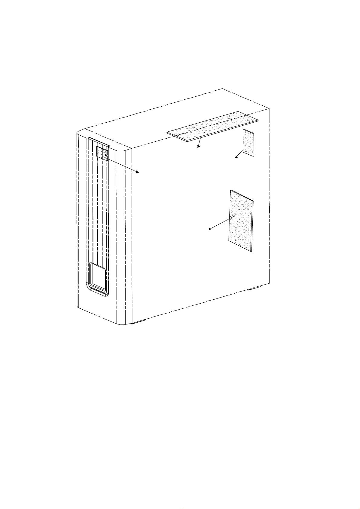
LOCATION OF PC BOARDS
LED
BOARD
1-2
AMPLIFIER
BOARD
INPUT
BOARD
POWER
BOARD
SPECIFICATIONS
SUBWOOFER
Subwoofer (not magnetically shielded design).......................................................................................................6.5"
Output Power.........................................................................................................................................75W (4Ω,DIN)
THD (Total Harmonic Distortion) ...................................................................................10% at 80 Hz (output power)
Reproduction Frequency Response.......................................................................................................30 Hz-180 Hz
Phase Switch....................................................................................................................................................00,180
Input Sensitivity (Subwoofer In).................................................................................................................200 mVrms
AC Power (for SW3500/37S) ..................................................................................................................120V / 60 Hz
AC Power (for SW3000/06S; SW3500/06S) .................................................................................110 ~ 127V / 60 Hz
AC Power (for SW3000/00S) ........................................................................................................ 220 ~ 240V / 50Hz
AC Power (for SW3000/00S;SW3500/02S) .......................................................................... 220 ~ 240V / 50 / 60 Hz
power Consumption...........................................................................................................53 W (at 1/8 Rated Power)
Dimensions (w x h x d)...................................................................................................130 mm x 337 mm x 375 mm
Weight...................................................................................................................................................................7 Kg
0
Page 3
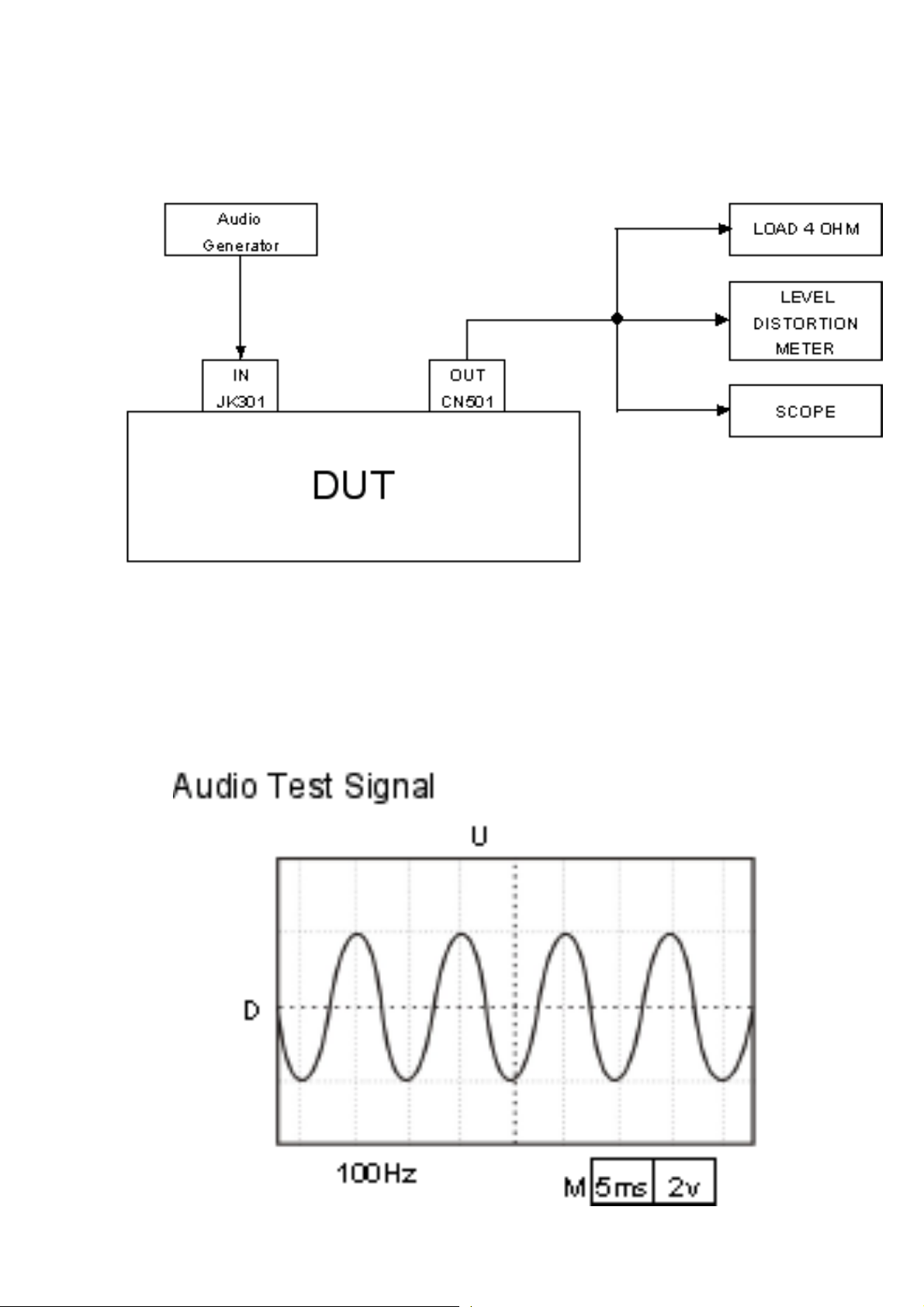
MEASUREMENT SETUP
1-3
Page 4

ESD & SAFETY INSTRUCTION
WARNING
GB
All ICs and many other semi-conductors are
susceptible to electrostatic discharges (ESD).
Careless handling during repair can reduce life
drastically.
When repairing, make sure that you are
connected with the same potential as the mass
of the set via a wrist wrap with resistance.
Keep components and tools also at this
potential.
F
ATTENTION
Tous les IC et beaucoup d’autres
semi-conducteurs sont sensibles aux
décharges statiques (ESD).
Leur longévité pourrait être considérablement
écourtée par le fait qu’aucune précaution n’est
prise à leur manipulation.
Lors de réparations, s’assurer de bien être relié
au même potentiel que la masse de l’appareil et
enfiler le bracelet serti d’une résistance de
sécurité.
Veiller à ce que les composants ainsi que les
outils que l’on utilise soient également à ce
potentiel.
D
Alle ICs und viele andere Halbleiter sind
empfindlich gegenüber elektrostatischen
Entladungen (ESD).
Unsorgfältige Behandlung im Reparaturfall kan
die Lebensdauer drastisch reduzieren.
Veranlassen Sie, dass Sie im Reparaturfall über
ein Pulsarmband mit Widerstand verbunden
sind mit dem gleichen Potential wie die Masse
des Gerätes.
Bauteile und Hilfsmittel auch auf dieses gleiche
Potential halten.
1-4
ESD
WARNUNG
WAARSCHUWING
NL
Alle IC’s en vele andere halfgeleiders zijn
gevoelig voor electrostatische ontladingen
(ESD).
Onzorgvuldig behandelen tijdens reparatie kan
de levensduur drastisch doen verminderen.
Zorg ervoor dat u tijdens reparatie via een
polsband met weerstand verbonden bent met
hetzelfde potentiaal als de massa van het
apparaat.
Houd componenten en hulpmiddelen ook op
ditzelfde potentiaal.
I
AVVERTIMENTO
Tutti IC e parecchi semi-conduttori sono
sensibili alle scariche statiche (ESD).
La loro longevità potrebbe essere fortemente
ridatta in caso di non osservazione della più
grande cauzione alla loro manipolazione.
Durante le riparazioni occorre quindi essere
collegato allo stesso potenziale che quello della
massa dell’apparecchio tramite un braccialetto
a resistenza.
Assicurarsi che i componenti e anche gli utensili
con quali si lavora siano anche a questo
potenziale.
GB
Safety regulations require that the set be restored to its original
condition and that parts which are identical with those specified,
be used.
NL
Veiligheidsbepalingen vereisen, dat het apparaat bij reparatie in
zijn oorspronkelijke toestand wordt teruggebracht en dat onderdelen,
identiek aan de gespecificeerde, worden toegepast.
F
Les normes de sécurité exigent que l’appareil soit remis à l’état
d’origine et que soient utiliséés les piéces de rechange identiques
à celles spécifiées.
D
Bei jeder Reparatur sind die geltenden Sicherheitsvorschriften zu
beachten. Der Original zustand des Geräts darf nicht verändert werden;
für Reparaturen sind Original-Ersatzteile zu verwenden.
“Pour votre sécurité, ces documents
doivent être utilisés par des spécialistes agréés, seuls habilités à réparer
votre appareil en panne”.
I
Le norme di sicurezza esigono che l’apparecchio venga rimesso
nelle condizioni originali e che siano utilizzati i pezzi di ricambio
identici a quelli specificati.
"After servicing and before returning set to customer perform a
leakage current measurement test from all exposed metal parts to
earth ground to assure no shock hazard exist. The leakage current
must not exceed 0.5mA."
Page 5
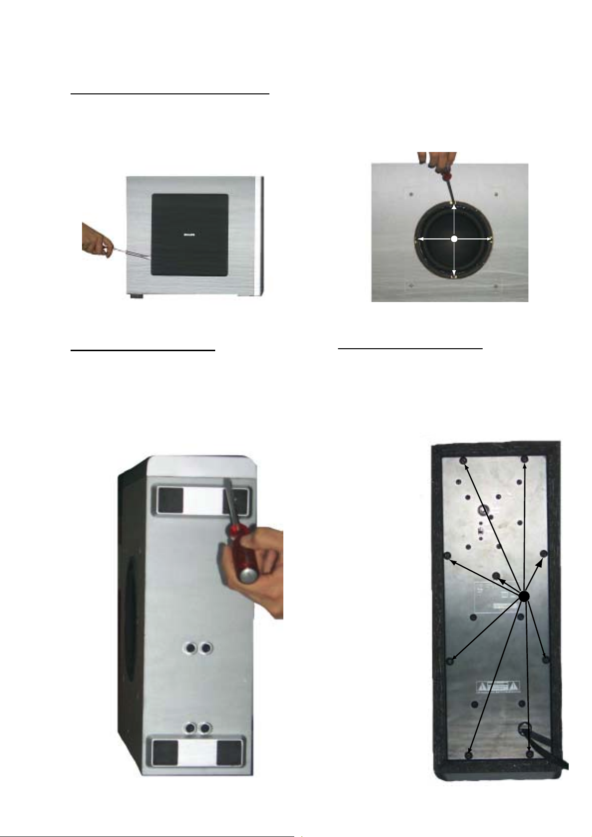
DISASSEMBLY INSTRUCTIONS
Dismantling the Grill Base & Speaker Driver
1. Place the Subwoofer Box as shown in the Picture 1
and use a screw driver to force open the Grill Base.
Caution: Take care the surface when take out the
Grill Base of Subwoofer
2-1
2. Place the Subwoofer Box as shown in the Picture 2
and loosen 4 screws A to remove the Speaker Driver.
A
Picture 1
Dismantling the Front Assembly
1. Place the Subwoofer Box as shown in the Picture 3
(Bottom view) and use a screw driver to force open the
front assembly.
Caution: Do not break the bundle of wires to the front.
Take care the surface when take out the front
panel of subwoofer
Picture 2
Dismantling the Rear assembly
1. Loosen 9 screws B as shown in the Picture 4 (Rear
View) to pull out the Printed Circuit Board assembly.
Caution: Do not break the bundle of wires to the front.
B
Picture 3
WARNING: THERE IS ONLY HAS A
LED BETWEEN FRONT PANEL AND
WOOD BOX. IF NO NECCESSARY,
PLEASE DON’T TRY TO OPEN THE
FRONT P ANEL!!!
Picture 4
Page 6
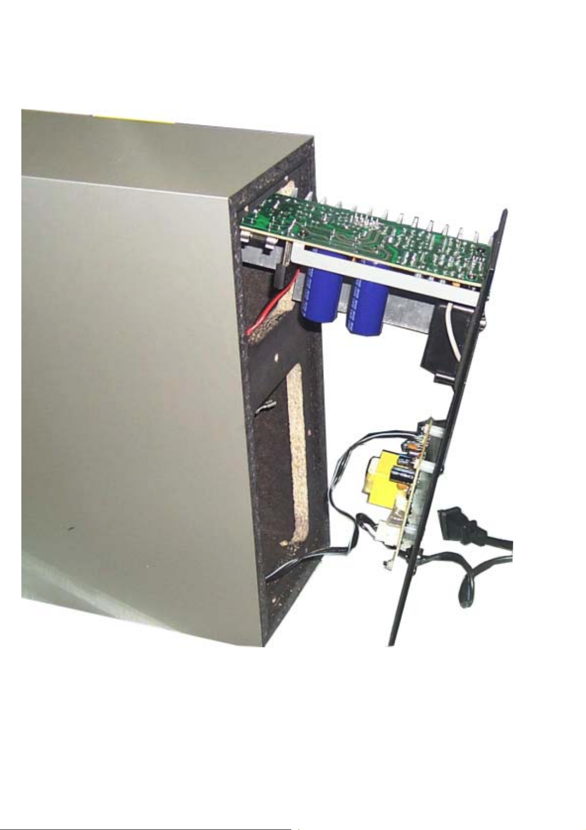
SERVICE POSITION
2-2
Page 7

SET BLOCK DIAGRAM
INPUT BOARD
3-1
3-1
AMPLIFIER BOARD
LED BOARD
POWER BOARD
Page 8

SET WIRING DIRGRAM
INPUT PCB
LVM0180C021
3-2
3-2
53
54
LVM0180C011
AMPLIFIER PCB
52
LVM0180C031
51
either
or
fixed
LED PCB
50
POWER PCB
detachable
Page 9

4-1
POWER BOARD
TABLE OF CONTENTS
PCB Layout View............................................................................4-1
Circuit Diagram...............................................................................4-2
Electrical Parts List.........................................................................4-3
4-1
PCB LAYOUT VIEW - POWER BOARD
C358 F3
C359 F3
C361 E1
C362 E2
C363 E2
C364 F2
C901 C3
CN901 B2
CN902 B3
D353 E3
D354 D1
D355 D1
D356 D3
F901 C2
Q354 E4
Q355 E4
Q357 E2
Q377 E3
R378 E3
R379 E3
R380 E4
R381 E4
R382 E2
R383 E2
RB351 F3
RL901 C4
T901 C4
ZD350 F2
Page 10

CIRCUIT DIAGRAM - POWER BOARD
4-2
4-2
C358 C3
C359 B1
C361 B2
C362 B2
C363 B2
C364 B1
C901 C4
CN901 C5
CN902 B5
D353 C3
D354 A3
D355 B3
D356 C3
!
!
!
!
!
F901 C4
Q354 C2
Q355 C3
Q357 B2
R377 C2
R378 C3
R379 B3
R380 C3
R381 C3
R382 B2
R383 B2
RB351 C1
RB901 C5
RB902 B5
RB906 A6
RL901 C4
T901 B6
T902 B4
ZD350 B2
!
!
!
!
!
Page 11

ELECTRICAL PARTS LIST - POWER BOARD
MISCELLANEOUS
CN901 9965 000 12636
CN902 9965 000 12636
F901 9965 000 12638
F901 4822 070 33152
F901 9965 000 12500
RL901 9965 000 09708
T902 9965 000 12602
T902 9965 000 12603
!
CONNECTOR 4 PIN P=3,96MM
!
CONNECTOR 4 PIN P=3,96MM
!
FUSE T2A 250V SLOW /00S/02S
!
FUSE T3,15A 250V SLOW /17S
!
FUSE T3,15A 250V SLOW /06S
!
RELAY GJ-SH-112DM 320OHM
!
TRANSFORMER 120V /06S/17S
!
TRANSFORMER 230V /00S/02S
CAPACITORS
C358 9965 000 12639 22UF 16V 20%
C359 9965 000 12559 100UF 16V 20%
C361 9965 000 12640 470UF 35V 20%
C362 2038 554 00065 100NF +80-20% 50V
C363 9965 000 12559 100UF 16V 20%
C364 2038 554 00065 100NF +80-20% 50V
C901 9965 000 12604 0,01UF 20%
4-3
RESISTORS
R377 4822 050 22203 22K 1% 0,6W
R378 9965 000 12641 62K 1/6W 5%
R379 4822 116 83868 150R 5% 0,5W
R380 9965 000 12629 30K 1/6W 5%
R381 4822 050 24703 47K 1% 0,6W
R382 4822 116 52218 300R 5% 0,5W
R383 4822 116 52263 2,7K 5% 0,5W
DIODES
D353 4822 130 30621 1N4148
D354 4822 130 31438!1N4001G
D355 4822 130 31438
D356 4822 130 31438
!
1N4001G
!
1N4001G
ZD350 9965 000 12642 ZENER 11,1-11,6V 0,5W
TRANSISTORS
Q354 4822 130 41198 2SC945P
Q355 4822 130 41198 2SC945P
Q357 4822 130 41198 2SC945P
Note: Only the parts mentioned in this list are normal service spare
parts.
Page 12

5-1
COMBI BOARD
5-1
INTERNAL IC DIAGRAM
TABLE OF CONTENTS
Internal IC Diagram...................................................................... 5-1
Circuit Diagram...............................................................................5-2
PCB Layout View............................................................................5-3
Electrical Parts List.........................................................................5-4
Page 13

CIRCUIT DIAGRAM - COMBI BOARD
5-2
5-2
!
AMPLIFIER SCHEMATIC
INPUT SCHEMATIC
!
!
LED SCHEMATIC
!
!
!
!
Page 14

PCB LAYOUT VIEW - COMBI BOARD
5-3
5-3
Page 15

5-45-4
ELECTRICAL PARTS LIST - AMPLIFIER PART ELECTRICAL PARTS LIST - AMPLIFIER PART
MISCELLANEOUS
CN906 9965 000 12617 CONNECTOR 3PIN PITCH=3,96 M
F902 4822 070 34002!FUSE T4A 250V SLOW
!
F903 4822 070 34002
FUSE T4A 250V SLOW
CAPACITORS
C303 4822 124 21913 1UF 20% 63V
C304 9965 000 08286 0,022UF 100V 5%
C305 4822 124 21913 1UF 20% 63V
C306 9965 000 08286 0,022UF 100V 5%
C340 9965 000 12559 100UF 16V 20%
C351 4822 124 22652 2,2UF 20% 50V
C352 2038 554 00065 100NF +80-20% 50V
C353 9965 000 12614 47PF 50V 5%
C354 9965 000 12522 4,7UF 50V 20%
C355 9965 000 12614 47PF 50V 5%
C356 9965 000 12559 100UF 16V 20%
C357 9965 000 12558 220UF 16V 20%
C360 9965 000 12559 100UF 16V 20%
C401 4822 122 33293 100PF 5% 50V
C402 4822 121 41935 12NF 5% 250V
C403 5322 121 42662 68NF 5% 250V
C404 5322 121 42662 68NF 5% 250V
C405 5322 121 42489 33NF 5% 250V
C406 4822 121 42077 6,8NF 10% 400V
C407 4822 124 22652 2,2UF 20% 50V
C410 4822 124 40433 47UF 20% 25V
C411 4822 124 40433 47UF 20% 25V
C412 4822 122 30103 22NF 80% 63V
C413 9965 000 12613 0,22UF 50V +80-20%
C414 9965 000 12613 0,22UF 50V +80-20%
C415 4822 122 30103 22NF 80% 63V
C422 5322 121 42662 68NF 5% 250V
C507 4822 122 33293 100PF 5% 50V
C508 5322 124 41945 22UF 20% 35V
C509 4822 124 40433 47UF 20% 25V
C510 9965 000 12614 47PF 50V 5%
C511 5322 121 42578 100NF 5% 250V
C512 9965 000 12536 100UF 50V 20%
C513 2038 554 00065 100NF +80-20% 50V
C514 9965 000 12536 100UF 50V 20%
C515 2038 554 00065 100NF +80-20% 50V
C516 4822 124 40433 47UF 20% 25V
C905 9965 000 12619
C906 9965 000 12619
!
6800UF 50V 20%
!
6800UF 50V 20%
C907 2038 554 00065 100NF +80-20% 50V
C908 2038 554 00065 100NF +80-20% 50V
C913 9965 000 11041 0,01UF 500V 20%
C914 9965 000 11041 0,01UF 500V 20%
C916 2038 554 00065 100NF +80-20% 50V
C917 4822 124 40207 100UF 20% 25V
C918 2038 554 00065 100NF +80-20% 50V
C919 4822 124 40207 100UF 20% 25V
RESISTORS
R304 4822 050 26202 6,2K 1% 0,6W
R340 9965 000 12620 1,8K 1/6W 5%
R350 4822 050 24703 47K 1% 0,6W
R351 4822 050 21004 100K 1% 0,6W
R352 4822 050 21004 100K 1% 0,6W
R353 9965 000 09725 4,7K 1/6W 5% CF
R354 9965 000 12621 2K 1/6W 5%
R355 9965 000 12622 2,2M 1/6W 5%
R356 4822 050 21003 10K 1% 0,6W
R357 9965 000 12623 82R 1/6W 5%
R358 9965 000 12624 270K 1/6W 5%
R359 9965 000 12624 270K 1/6W 5%
R360 4822 050 21003 10K 1% 0,6W
R361 4822 050 21003 10K 1% 0,6W
R362 9965 000 12519 1K 1/6W 5% CF
R363 9965 000 12625 560K 1/6W 5%
R364 9965 000 08284 220K 1/6W 5% CF
R365 9965 000 12626 1M 1/6W 5%
R366 9965 000 12627 680K 1/6W 5%
R367 9965 000 12628 82K 1/6W 5%
R368 9965 000 12627 680K 1/6W 5%
R369 4822 050 22203 22K 1% 0,6W
R370 4822 050 21003 10K 1% 0,6W
R371 9965 000 12629 30K 1/6W 5%
R373 9965 000 12620 1,8K 1/6W 5%
R374 4822 050 22702 2,7K 1% 0,6W
R375 9965 000 13450 910R 5% 1/6W
R376 4822 050 24703 47K 1% 0,6W
R401 9965 000 12631 180K 1/6W 5%
R402 4822 050 21003 10K 1% 0,6W
R403 9965 000 08285 18K 1/6W 5% CF
R404 4822 050 21504 150K 1% 0,6W
R405 9965 000 09724 3,9K 1/6W 5% CF
R406 9965 000 08285 18K 1/6W 5% CF
R410 4822 050 21001 100R 1% 0,6W
R411 4822 050 21001 100R 1% 0,6W
R412 9965 000 08285 18K 1/6W 5% CF
R413 9965 000 09725 4,7K 1/6W 5% CF
R414 9965 000 09725 4,7K 1/6W 5% CF
R513 9965 000 12519 1K 1/6W 5% CF
R513 9965 000 09725 4,7K 1/6W 5% CF
R514 4822 050 24703 47K 1% 0,6W
R515 9965 000 12519 1K 1/6W 5% CF
R517 9965 000 12629 30K 1/6W 5%
R518 9965 000 12629 30K 1/6W 5%
R519 4822 116 81753 4,7R 5% 0,5W
R520 4822 050 23303 33K 1% 0,6W
R521 4822 050 21502 1,5K 1% 0,6W
R522 4822 116 52291 56K 5% 0,5W
R523 4822 116 52228 680R 5% 0,5W
R902 9965 000 12632 1K 1W 5%
R903 9965 000 12632 1K 1W 5%
DIODES
D351 4822 130 30621 1N4148
D352 4822 130 30621 1N4148
D504 4822 130 31438
DB901 4822 130 70035
!
1N4001G
!
RS402L
ZD501 4822 130 34281 BZX79-B15
ZD502 9965 000 12635 ZENER 9,1-9,5V 0,5W
ZD901 4822 130 34281 BZX79-B15
ZD902 4822 130 34281 BZX79-B15
TRANSISTORS & INTEGRATED CIRCUITS
IC351 4822 209 83631 NJM4558DD
IC401 4822 209 32742 TL074IN
IC502 9965 000 12633
!
LM3886T POWER IC
Q351 4822 130 41198 2SC945P
Q352 9965 000 12634 2SC946P
Q353 4822 130 41198 2SC945P
Note: Only the parts mentioned in this list are normal service spare
parts.
ELECTRICAL PARTS LIST - INPUT PART
MISCELLANEOUS
JK301 4822 267 41238 CINCH SOCKET 1P, AUDIO-IN
SW301 4822 277 11821 SLIDE SWITCH, PHASE
CAPACITORS
C301 4822 122 33293 100PF 5% 50V
C302 4822 124 21913 1UF 20% 63V
RESISTORS
R301 4822 050 21003 10K 1% 0,6W
R302 4822 050 25602 5,6K 1% 0,6W
R303 4822 050 21003 10K 1% 0,6W
Note: Only the parts mentioned in this list are normal service spare
parts.
ELECTRICAL PARTS LIST - LED PART
9965 000 12978 LED PCB ASSEMBLY
LD401 9965 000 12618 LED RED/GREEN
Note: Only the parts mentioned in this list are normal service spare
parts.
Page 16

MECHANICAL EXPLODED VIEW
LINE CORD (TYPE)
6-1 6-1
A2
use for SW3000/00S ; SW3500/02S
use for SW3000/00S/06S ; SW3500/06S /17S
A1
Page 17

6-2
13-2
MECHANICAL & ACCESSORIES PARTS LIST - MAIN UINT
A1 9965 000 12977 FRONT PANEL ASSY SW3000/00S/06S
A1 9965 000 12983 FRONT PANEL ASSY SW3500/02S/06S
A1 9965 000 12985 FRONT PANEL ASSY SW3500/17S
A2 9965 000 12980 CLOTH FRAME ASSY SW3000 GREY
A2 9965 000 12984 CLOTH FRAME ASSY SW3500 ORANGE
4 9965 000 12978 LED PCB ASSEMBLY
8 9965 000 12979 MAINS TRANSFORMER 120V /06S/17S
8 9965 000 12982 MAINS TRANSFORMER 230V /00S/02S
29 9965 000 12818 MAINS CORD /17S FIXED
29 9965 000 12819 MAINS CORD /06S FIXED
29 9965 000 12820 MAINS CORD /00S/02S DETACHABLE
29 9965 000 12821 MAINS CORD /00S AUSTRALIA FIXED
30 9965 000 07092 BUSHING, FIXED CORD
30 9965 000 12443 AC SOCKET, DETACHABLE CORD
38 4822 532 13065 WASHER
39 9965 000 08278 SPEAKER DRIVER 100W 6,5” 4OHM
44 9965 000 12981 RUBBER FOOT
SCREW LIST - MAIN UINT
5 D3 x 6
6 M3,8 x 25
14 M3 x 8
26 M2 x 6
27 D3 x 10
28 D3,6 x 14
31 M3 x 22
36 M3 x 14
46 M3 x 12
Note: Only the parts mentioned in this list are normal service spare
parts.
 Loading...