

Page 1
Register your product and get support at
www.philips.com/welcome
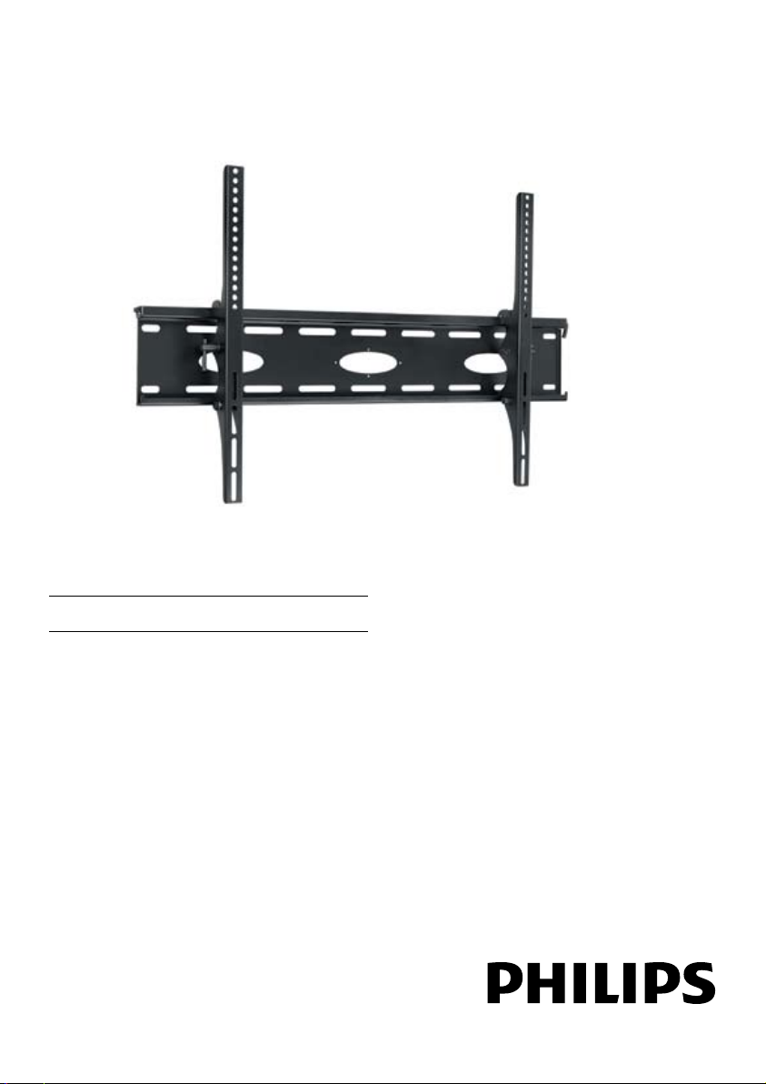
EN Tilting wall mount 3
SQM5322/27
Support mural inclinable 9
FR
ES Soporte de pared basculante 16
1
Page 2

2
Table of contents
1 Important 3
2 Your tilting wall mount
2.1 What’s in the box 4
2.2 What you’ll also need 4
3 Installing your wall mount
3.1 Mounting the wall plate (drywall) 5
3.2 Mounting the wall plate (concrete) 5
3.3 Attaching the arms to the display 6
4 Mounting and adjusting
5 Guarantee and service
3
5
7
8
Page 3

1 Important
Take time to read this manual before you
use your wall mount. It contains important
information and notes regarding operating your
wall mount.
© 2008 Koninklijke Philips Electronics N.V.
All rights reserved. Reproduction in whole or in
part is prohibited without the written consent of
the copyright owner. Trademarks are the
property of Koninklijke Philips Electronics N.V.
or their respective owners.
B Warnings
• Make sure these instructions are read
and thoroughly understood before
attempting installation. If you are
unsure of any part of this installation,
contact a professional installer for
assistance or contact Customer Service
at 1-919- 573-7854.
• This product has been designed
for application on a vertical wall in
commercial and residential buildings,
constructed of wood wall studs or
masonary (solid concrete, brick, and
stone). If you are unsure of your wall
composition or for assistance with other
surfaces, contact a qualified installer.
• This product is not designed for use on
walls constructed of metal studs. If you
are unsure of your wall composition
or for assistance with other surfaces,
contact a qualified installer.
• The wall or mounting surface must be
capable of supporting the combined
weight of the mount and the display;
otherwise the structure must be
reinforced.
• Do not exceed the maximum load
capacity of 165lbs for this product.
• Safety gear and proper tools must
be used. Failure to do so can result in
property damage and/or serious injury.
• A minimum of two people are required
for this installation. Do not attempt
to install this mount alone under any
circumstance.
• Follow all instructions and
recommendations regarding adequate
ventilation and suitable locations for
mounting your display. Consult the
owner’s manual for your display for
more information.
• This mount is equipped with a safety
device that must be used whenever
the mount holds a display. Not using
the safety device can cause property
damage, serious injury, or death.
2 Your tilting wall mount
Congratulations on your purchase and welcome
to Philips!
To fully benefit from the support that Philips
offers, register your product at
www.philips.com/welcome.
Designed to fit most TV brands with a focus
on safety and ease of use. Includes Easy 1-2-3
installation kit, complete with: all necessary
hardware for mounting on different types of
walls, mounting templates, stud finder and
bubble level. C-UL US listed for weight capacity
up to 165lbs.
3
Page 4
4
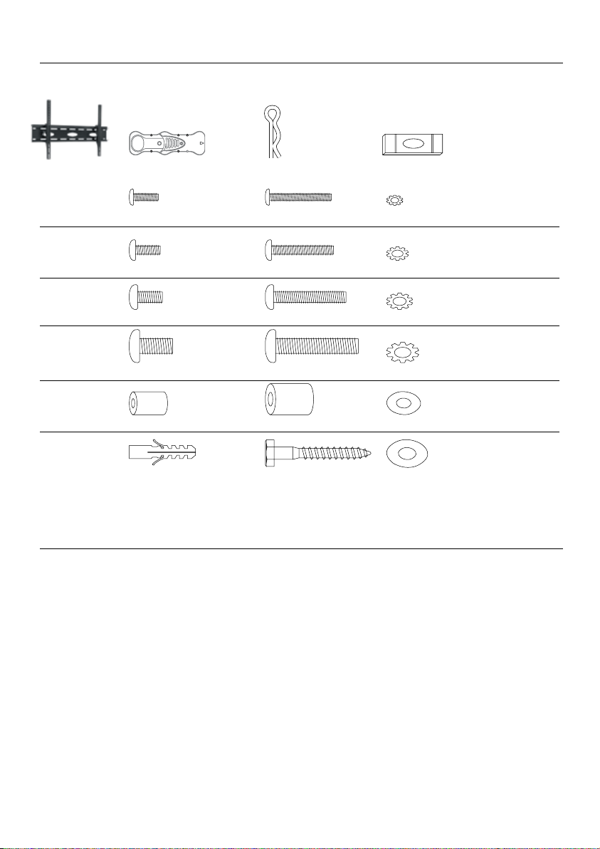
2.1 What’s in the box.
Wall mount Stud finder Cotter pin Bubble level
Bag #1 (A) M4x12 Bolt (x4) (B) M4x30 Bolt (x4) (C) M4 Lock Washer (x4)
Bag #2 (D) M5x12 Bolt (x4) (E) M5x30 Bolt (x4) (F) M5 Lock Washer (x4)
Bag #3 (G) M6x12 Bolt (x4) (H) M6x35 Bolt (x4) (I) M6 Lock Washer (x4)
Bag #4 (J) M8x16 Bolt (x4) (K) M8x40 Bolt (x4) (L) M8 Lock Washer (x4)
Bag #5 (M) Small Spacer (x4) (N) Large Spacer (x4) (O) M6 Washer (x4)
Bag #6 (P) Concrete Anchor (x6) (Q) M8x63 Lag Bolt (x6) (R) Lag Bolt Washer (x6)
2.2 What you’ll also need.
• Phillips head screwdriver
• Ratchet or driver with 1/2” (13 mm) socket
• Portable or electric drill
• 1/4” (6 mm) drill bit and stud finder for drywall installation
• 3/8” (10 mm) masonry bit for concrete installation
Page 5
3 Installing your wall mount
In this chapter, the basic steps to get you started
are described.
B Warning
Carefully read the safety precautions
in “Section 1 Important” before you
install the wall mount.
3.1 Mounting the wall plate (drywall)
B Warning
For safety reasons, this mount must
be secured to three adjacent wood
studs at least 16” apart. The studs
must be capable of supporting the
combined weight of the mount and
display.
See enclosed mounting template for
1
diagram and guide of how to mount
properly on the wall.
Using a stud finder, locate and mark three
2
adjacent studs for securing the mount
(make sure your marks are in the center
of each stud). You can use your own stud
finder or the one included in the hardware
kit.
D Note
Once studs have been located you will
need to verify with a hammer and a
nail
A) Simply place the nail over your
mark on the wall and tap in with
hammer. If the nail encounters
resistance and is secure in wall you
have veried a stud location
B) If it just pushes through with no
resistance you will need to start
over and locate the stud.
Using the enclosed mounting template,
3
place the diagram against the wall and mark
six locations (two per stud) on the wall
where the mount Is to be Installed. Be sure
to use the center of each stud.
With the help of another person, place the
4
mount against the wall and level it using the
bubble guide.
5 While another person holds the mount in
place, mark six locations (two per stud) on
the wall where the mount is to be installed.
Be sure to use the center of each stud.
(these marks should line up with the ones
made in step 3 above using the template).
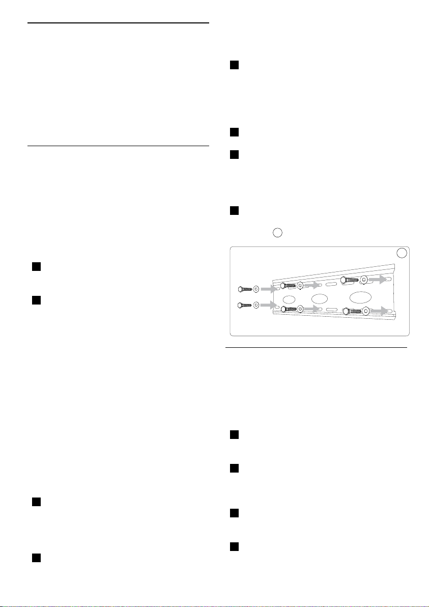
6 Set the mount aside and drill a 1/4” (6 mm)
pilot hole at each marked location.
7 Place the mount back against the wall and
secure it using the lag bolts (Q) and lag bolt
washers (R) provided. Do not over-tighten
these bolts and do not release the mount
until all bolts are in place.
Once all (6) lag bolts are in place you must
8
tighten each one. Be sure not to over
tighten.
1
3.2 Mounting the wall plate (concrete)
B Warning
For safety reasons, the concrete wall
must be capable of supporting the
combined weight of the mount and
display.
See enclosed mounting template for
1
diagram and guide of how to mount
properly on the wall.
Using the enclosed mounting template,
2
place the diagram against the wall and mark
six locations on the wall where the mount
Is to be Installed.
With the help of another person, place the
3
mount against the wall and level it using the
bubble guide.
While another person holds the mount in
4
place, mark six locations on the wall where
1
5
Page 6
6
the mount is to be installed.
5 Set the mount aside and drill a 3/8” (10
mm) pilot hole at each marked location.
Remove any excess dust from the holes.
6 Insert a concrete anchor (P) into each hole
so that it is flush with the concrete surface.
A hammer can be used to lightly tap the
anchors into place if necessary.
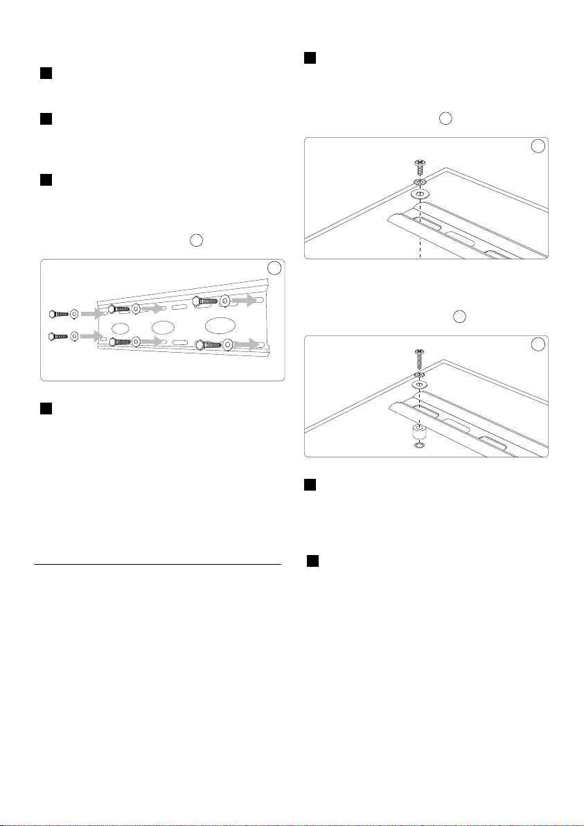
7 Place the mount back against the wall and
secure it using the lag bolts (Q) and lag bolt
washers (R) provided. Do not over-tighten
these bolts and do not release the mount
until all bolts are in place. 2
8 Once all (6) lag bolts are in place you must
tighten each one. Be sure not to over
tighten.
1 Examine the back of your television.
If the back of your display is at:
You will be using one of the shorter bolts
from the hardware kit.
2
If the back of your display is curved
or recessed: You will be using one of the
longer bolts and a spacer.
3
3
4
4
D Note
If the concrete wall is covered
by a layer of plaster or drywall,
the concrete anchor must pass
completely through the layer to rest
ush with the concrete surface.
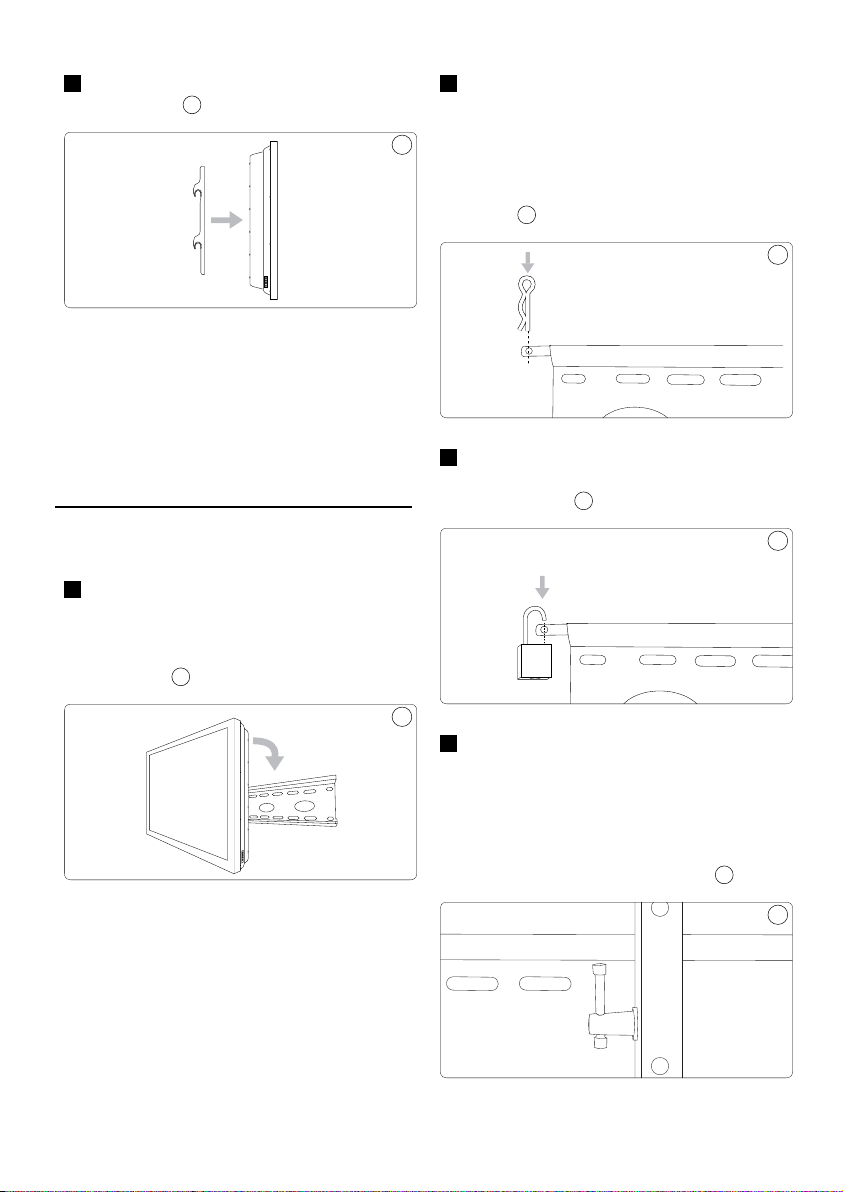
3.3 Attaching the arms to the display
B Warning
Use extra care during this part of
the installation. Avoid laying your
display face down if possible as it may
damage the viewing surface.
Determine the correct diameter bolt to
2
use by trying one bolt each from Bags 1
- 4 of the hardware kit. Do not force any
of the bolts – if you feel resistance stop
immediately to avoid damaging your display
.3 Attach the arms to the back of your display
using the bolts identified in Steps 1 and 2
and the corresponding lock washer (C, F, I,
or L). You will need to use the M6 washers
(O) if you are using the M4, M5, or M6 bolts.
If your display has a curved or recessed
back, you may also need to use a Spacer (M
or N).
Page 7
4 Make sure the screws are snug, but do not
over-tighten. 5
E Tip
Use a longer bolt and spacer for
displays with curved or recessed
backs. Do not use the M6 Washer (O)
if you are using the M8 Bolts (J or K).
2 This MUST be done in order to secure
the display to the mount. NOTE: A cotter
pin (included) Is used to secure the arms
5
to the mount OR a padlock (not included)
can be inserted into the hole at the end of
the saftey bar to help prevent theft of your
display.
7
A small padlock can be used to help
3
prevent theft of your display.
(not included)
8
7
4 Mounting and adjusting
With the help of another person, carefully
1
lift your display and place it on the wall
plate. Do not release the display until the
mounting arms have securely hooked onto
the mount.
B Warning
Insert the safety bar at the top of the
mount to avoid having the display
accidentally knocked off the mount.
6
6
To adjust the tilt position, have one person
4
hold the display in position while another
person loosens the two tilt adjustment
knobs located on either side of the wall
plate. Once the knobs are loose, move the
display to the desired angle. Re-tighten the
knobs before releasing the display.
8
9
9
7
Page 8

5 Guarantee and service
Please contact Philips directly if you have any
questions in the installation process of the wall
mount. Call 1-919-573-7854.
Limited Two-Year Warranty
Philips warrants that this product shall be free
from defects in material, workmanship and
assembly, under normal use, in accordance with
the specications and warnings, for two years
from the date of your purchase of this product.
This warranty extends only to the original
purchaser of the product, and is not transferable.
To exercise your rights under this warranty, you
must provide proof of purchase in the form of
an original sales receipt that shows the product
name and the date of purchase. For customer
support or to obtain warranty service, please
call 919-573-7854. THERE ARE NO OTHER
EXPRESS OR IMPLIED WARRANTIES. Philips’
liability is limited to repair or, at its sole option,
replacement of the product. Incidental, special
and consequential damages are disclaimed where
permitted by law. This warranty gives you specic
legal rights. You may also have other rights that
vary from state to state.
Register your product and get support at
www.philips.com/welcome
8
Page 9

9
Table des matières
1 Consignes de sécurité
importantes 10
2 Votre support mural inclinable
2.1 Contenu de la boîte 11
2.2 Outils requis 11
3 Installation du support mural
3.1 Installation de la plaque murale sur
un mur de gypse 12
3.2 Installation de la plaque murale sur
un mur de béton 12
3.3 Fixation des bras sur le téléviseur 13
4 Montage et réglage
5 Garantie et service
10
12
13
15
Page 10

1 Consignes de sécurité importantes
Lisez ce manuel attentivement avant d’utiliser
votre support mural. Il contient des informations
importantes concernant l’installation et
l’utilisation du support.
© Koninklijke Philips Electronics N.V., 2008.
Tous droits réservés. La reproduction de la
totalité ou d’une partie du présent manuel est
interdite sans l’autorisation écrite du titulaire du
droit d’auteur. Les marques de commerce sont
la propriété de Koninklijke Philips Electronics
N.V. ou de leur détenteur respectif.
B Avertissements
• Assurez-vous de bien comprendre
les instructions avant d’installer le
support mural. Si vous n’êtes pas
certain de bien comprendre une étape,
consultez un installateur professionnel
ou communiquez avec le service à la
clientèle, au 1 (919) 573-7854.
• Le support mural est conçu pour être
fixé sur les murs ayant une ossature
en bois et sur les murs en béton, en
briques ou en pierres. Si vous n’êtes pas
certain de la composition du mur ou si
vous voulez installer le support mural
sur une autre surface, consultez un
installateur professionnel.
• Le support mural n’est pas conçu
pour être fixé aux murs de gypse dont
la structure est faite de montants
métalliques. Si vous n’êtes pas certain
de la composition du mur ou si vous
voulez installer le support mural
sur une autre surface, consultez un
installateur professionnel.
• Le mur ou la surface porteuse choisie
doit pouvoir supporter le poids combiné
du support et du téléviseur. Si le poids
total est trop important pour la surface
choisie, celle-ci doit être renforcée.
• Ne dépassez pas la capacité de charge
maximum du produit, soit 74,84 kg
(165 lb).
• Pour réduire les risques de dommages
matériels et de blessure, portez
l’équipement de sécurité nécessaire et
utilisez les outils appropriés.
• L’installation doit être effectuée par au
moins deux personnes. N’essayez pas
d’installer le support mural sans l’aide
d’une autre personne.
• Suivez toutes les instructions et
recommandations concernant le
dégagement autour du téléviseur et
l’emplacement choisi pour le support
mural. Pour en savoir davantage,
consultez la documentation du
téléviseur.
• Le support mural est doté d’une vis
de verrouillage de sûreté qui doit
être utilisée lorsqu’un téléviseur y est
installé. Si la vis de sûreté n’est pas
utilisée, le support mural risque de
causer des dommages matériels, des
blessures ou même la mort.
2 Votre support mural inclinable
Félicitations pour votre achat et bienvenue dans
le monde Philips!
Pour bénéficier pleinement de l’assistance
offerte par Philips, enregistrez votre produit sur
le site www.philips.com/welcome
Conçu pour s’adapter à la plupart des marques
de téléviseur, en gardant à l’esprit la sécurité et
la facilité d’utilisation. Comprend une trousse
d’installation en trois étapes faciles avec tout
le matériel nécessaire pour fixer le support
sur différents types de murs, des modèles
de montage, un détecteur de montant et un
niveau à bulle. Homologué C-UL pour un poids
maximal de 74,84 kg (165 lb).
10
Page 11

11
2.1 Contenu de la boîte
Support mural Détecteur de montants Goupille fendue Niveau à bulle d’air
Sac #1 (A) Boulon M4x12 (x4) (B) Boulon M4x30 (x4) (C) Rondelle frein M4 (x4)
Sac #2 (D) Boulon M5x12 (x4) (E) Boulon M5x30 (x4) (F) Rondelle frein M5 (x4)
Sac #3 (G) Boulon M6x12 (x4) (H) Boulon M6x35 (x4) (I) Rondelle frein M6 (x4)
Sac #4 (J) Boulon M8x16 (x4) (K) Boulon M8x40 (x4) (L) Rondelle frein M8 (x4)
Sac #5 (M) Petite rondelle (N) Grande rondelle (O) Rondelle M6 (x4)
d’espacement (x4) d’espacement (x4)
Sac #6 (P) Ancrage en béton (x6) (Q) Boulon M8x63 (x6) (R) Rondelle pour boulon (x6)
2.2 Outils requis
• Tournevis cruciforme
• Clé à cliquet ou broche mandarin avec douille de 1/2 po (13 mm)
• Perceuse portative ou électrique
• Foret de 1/4 po (6 mm) et détecteur de montant pour l’installation sur cloison sèche
• Foret de maçonnerie de 3/8 po (10 mm) pour l’installation sur béton
Page 12

3 Installation du support mural
Cette section explique les étapes de base de l’installation.
B Avertissement
Avant d’installer le support mural,
lisez attentivement la section 1,
Consignes de sécurité importantes.
3.1 Installation de la plaque murale sur un
mur de gypse
B Avertissement
Pour assurer une installation sécuritaire,
le support mural doit être xé à trois
montants en bois, espacés d’au moins
40,64 cm (16 po). Les montants doivent
pouvoir supporter le poids combiné du
support et du téléviseur.
1 Reportez-vous au gabarit de montage
fourni pour savoir comment fixer le
support au mur correctement.
2 À l’aide d’un détecteur de montants, repérez
et marquez l’emplacement des trois montants
adjacents où vous voulez fixer le support
mural, en vous assurant que la marque est
bien au centre de chaque montant. Vous
pouvez utiliser votre détecteur de montant
ou celui livré avec le support mural.
D Remarque
Après avoir marqué le centre des
montants, vériez la solidité de
l’emplacement en procédant comme
suit :
A) Avec un marteau, enfoncez un
clou partiellement sur la marque.
Si le clou s’enfonce avec résistance
et qu’il est bien solide, la marque
est vis-à-vis un montant.
B) Si le clou s’enfonce sans résistance,
recommencez la procédure de
localisation du montant.
3 Placez le gabarit fourni sur le mur et
marquez l’emplacement des 6 trous (deux
par montant) où sera fixée la plaque
murale. Assurez-vous que les marques sont
bien au centre de chaque montant.
12
4
Avec l’aide d’une autre personne, placez la
plaque sur le mur et utilisez le niveau fourni
pour vous assurer qu’elle est parfaitement
horizontale.
5
Pendant que l’autre personne tient la plaque
en place, marquez l’emplacement des 6 trous
(deux par montant) où sera fixée la plaque
murale. Assurez-vous que les marques sont
bien au centre de chaque montant. (Ces
marques doivent s’aligner avec celles qui ont
été faites à l’étape 3 en utilisant le gabarit.)
6
Mettez la plaque de côté et percez un trou de
guidage de 6 mm (1/4 de po) sur chaque marque.
7
Positionnez le support dos au mur et fixez-
le à l’aide des boulons (Q) et des rondelles
de boulons (R) fournis. Ne serrez pas trop
les boulons et tenez le support jusqu’à ce
que tous les boulons soient bien en place.
8 Une fois les 6 boulons placés, vissez-les
chacun solidement. Ne les serrez pas trop. 1
1
3.2 Installation de la plaque murale sur un
mur de béton
B Avertissement
Pour assurer une installation
sécuritaire, le mur de maçonnerie
doit pouvoir supporter le poids
combiné du support et du téléviseur.
1 Reportez-vous au gabarit de montage
fourni pour savoir comment fixer le
support au mur correctement.
2 Placez le gabarit fourni sur le mur et
marquez l’emplacement des 6 trous où sera
fixée la plaque murale.
3 Avec l’aide d’une autre personne, placez la
plaque sur le mur et utilisez le niveau fourni
pour vous assurer qu’elle est parfaitement
horizontale.
Page 13

13
4 Pendant que l’autre personne tient la
plaque en place, marquez l’emplacement
des 6 trous où sera fixée la plaque murale.
5 Mettez la plaque de côté et percez un
trou de guidage de 10 mm (3/8 de po)
sur chaque marque. Enlevez l’excès de
poussière dans les trous.
6 Enfoncez une cheville pour mur de
béton (B) dans chaque trou, pour qu’elle
soit bien encastrée sans dépasser le mur,
en utilisant un marteau au besoin.
7 Positionnez le support dos au mur et fixez-le
à l’aide des boulons (Q) et des rondelles de
boulons (R) fournis. Ne serrez pas trop les
boulons et tenez le support jusqu’à ce que
tous les boulons soient bien en place. 2
8 Une fois les 6 boulons placés, vissez-les
chacun solidement. Ne les serrez pas trop.
D Remarque
Si le mur de maçonnerie est
recouvert de plâtre ou de gypse,
les chevilles doivent traverser
complètement la surface externe,
sans dépasser le mur de maçonnerie.
3.3 Fixation des bras sur le téléviseur
B Avertissement
Prenez toutes les précautions qui
s’imposent lors de cette partie de
l’installation. Ne posez pas l’écran du
téléviseur face au sol, car la surface
de visionnement risquerait d’être
endommagée.
1 Examinez la partie arrière du téléviseur.
Si l’arrière du téléviseur est plat :
utilisez un des boulons courts fournis avec
le support.
3
Si l’arrière du téléviseur est courbé ou
2
avec une rondelle d’espacement.
Déterminez quel diamètre de boulon est
2
en retrait :
utilisez un des boulons longs
nécessaire en essayant un boulon des sacs
1 à 4 de la trousse de matériel. Ne forcez
pas les boulons : si vous sentez une
résistance, arrêtez immédiatement pour
éviter d’endommager le téléviseur
.3 Fixez les bras à l’arrière du téléviseur à
l’aide des boulons identifiés aux étapes 1 et
2 avec les rondelles frein correspondantes
(C, F, I ou L). Vous aurez besoin des
rondelles M6 (O) si vous utilisez les
boulons M4, M5 ou M6. Si l’arrière de
votre écran est courbé ou en retrait, vous
aurez peut-être besoin d’une rondelle
d’espacement (M ou N).
3
4
4
Page 14

4 Assurez-vous que les vis sont serrées, mais
pas trop. 5
E Conseil
Utilisez un boulon plus long et une
rondelle d’espacement pour les
téléviseurs dont l’arrière est courbé
ou encastré. N’utilisez pas la rondelle
M6 (O) si vous utilisez les boulons M8
(J ou K).
4 Montage et réglage
Avec l’aide d’une autre personne, soulevez
1
l’écran avec précautions puis placez-le sur
la plaque murale. Tenez l’écran en place
jusqu’à ce que les bras de montage soient
fixés solidement sur le support.
6
2 Cette étape DOIT être effectuée pour fixer
l’écran sur le support. REMARQUE : Une
goupille fendue (incluse) est utilisée pour
5
fixer les bras sur le support; un cadenas
(non inclus) peut aussi être inséré dans le
trou à l’extrémité de la barre de sécurité
pour empêcher le vol du téléviseur.
Vous pouvez utiliser un petit cadenas pour
3
empêcher le vol de votre téléviseur
(non inclus).
Pour régler la position inclinée, demander
4
6
à quelqu’un de tenir le téléviseur en place
8
alors que vous desserrez les deux boutons
de réglage d’inclinaison situés d’un des
côtés de la plaque murale. Lorsque les
boutons sont desserrés, positionnez l’écran
dans l’angle que vous désirez. Resserrez
ensuite les boutons avant de relâcher
l’écran.
9
7
7
8
B Avertissement
Vous devez serrer la barre de sûreté
pour empêcher que le téléviseur
tombe accidentellement du support.
14
9
Page 15

5 Garantie et service
Si vous avez des questions au sujet du support
mural ou de son installation, communiquez
avec le service à la clientèle de Philips au
1 (919) 573-7854.
Garantie limitée de deux ans
Philips garantit que ce produit est exempt de
défauts de matériel et de main-d’œuvre, dans
des conditions normales d’utilisation conformes
aux spécications et aux avertissements, pour
une période de deux ans à compter de la date
d’achat du produit. Cette garantie s’applique
uniquement à l’acquéreur initial du produit et
n’est pas cessible. Pour exercer vos droits dans
le cadre de cette garantie, vous devez fournir le
reçu de caisse original sur lequel gure le nom
du produit et la date d’achat. Pour communiquer
avec le service à la clientèle ou obtenir des
services en vertu de la garantie, composez
le 1 (919) 573-7854. IL N’EXISTE AUCUNE
AUTRE GARANTIE EXPRESSE OU IMPLICITE.
La responsabilité de Philips se limite à la
réparation ou, à sa discrétion, au remplacement
du produit. Philips décline toute responsabilité
quant aux dommages accidentels, spéciaux ou
induits, lorsque la loi l’autorise. Cette garantie
vous confère des droits juridiques spéciques.
Vous pouvez également bénécier d’autres
droits qui varient selon les pays.
Enregistrez votre produit et obtenez de l’aide
sur le site www.philips.com/welcome.
15
Page 16

16
Índice
1 Importante 17
2 Soporte de pared basculante
2.1 Contenido del kit 18
2.2 Otros elementos necesarios 18
3 Instalación del soporte de pared
3.1 Montaje de la placa de pared
(para paredes de cartón yeso) 19
3.2 Montaje de la placa de pared
(para paredes de hormigón) 19
3.3 Colocación de los brazos en la
pantalla 20
4 Montaje y ajuste
5 Garantía y servicio técnico
17
19
21
22
Page 17

1 Importante
Lea este manual con atención antes de utilizar el
soporte de pared, pues contiene información y
datos importantes que le servirán de gran ayuda.
© 2008 Koninklijke Philips Electronics N.V.
Todos los derechos reservados. Queda
prohibida la reproducción total o parcial sin la
autorización escrita del titular de los derechos
de propiedad intelectual. Las marcas comerciales
son propiedad de Koninklijke Philips Electronics
N.V. o sus respectivos titulares.
B Advertencias
• Lea las instrucciones con detenimiento
antes de comenzar la instalación. Si
tiene dudas, comuníquese con un
instalador profesional o con el servicio
de atención al cliente al 1-919-573-7854.
• Este producto ha sido diseñado para
utilizarse en edificios comerciales y
viviendas, sobre paredes con vigas de
madera o de mampostería (hormigón,
ladrillo o piedra). Si no sabe con
seguridad de qué material son sus
paredes o si desea colocar el soporte
en otro tipo de superficie, pónganse en
contacto con un instalador profesional.
• Este producto no puede utilizarse en
paredes con vigas de metal. Si no sabe
con seguridad de qué material son sus
paredes o si desea colocar el soporte
en otro tipo de superficie, pónganse en
contacto con un instalador profesional.
• La pared o superficie debe ser capaz
de sostener el peso del soporte y de la
pantalla. De lo contrario, la estructura
deberá ser reforzada.
• No exceda los 74 kg. de capacidad de
carga máxima del producto.
• Utilice equipos de seguridad y
herramientas apropiadas. De no
hacerlo, podría ocasionar serios daños
materiales o sufrir lesiones graves.
• La instalación debe ser realizada
por dos personas o más. No intente
colocar el soporte sin ayuda en ninguna
circunstancia.
• Siga todas las instrucciones y
recomendaciones de ventilación
y ubicación del soporte. Para más
información, consulte el manual de la
pantalla.
• Este soporte incluye un dispositivo
de seguridad que debe utilizarse
siempre para sostener la pantalla. De
lo contrario, pueden ocasionarse daños
materiales, lesiones graves y hasta la
muerte.
2 Soporte de pared basculante
Felicitaciones por su compra y bienvenido a
Philips.
Para poder recibir la asistencia técnica de Philips,
registre su producto en www.philips.com/welcome.
El diseño de este producto se adapta a casi
todas las marcas de televisores y es seguro y
fácil de usar. El kit de instalación simple incluye
todos los accesorios necesarios para diferentes
tipos de pared: plantillas de montaje, detector
de vigas y nivel de burbuja. Capacidad de hasta
74 kg. conforme a C-UL US.
17
Page 18

18
2.1 Contenido del kit
Soporte Detector de vigas Chaveta Nivel de burbuja
Kit Nº 1 (A) 4 pernos M4x12 (B) 4 pernos M4x30 (C) 4 arandelas de bloqueo M4
Kit Nº 2 (D) 4 pernos M5x12 (E) 4 pernos M5x30 (F) 4 arandelas de bloqueo M5
Kit Nº 3 (G) 4 pernos M6x12 (H) 4 pernos M6x35 (I) 4 arandelas de bloqueo M6
Kit Nº 4 (J) 4 pernos M8x16 (K) 4 pernos M8x40 (L) 4 arandelas de bloqueo M8
Kit Nº 5 (M) 4 espaciadores pequeños (N) 4 espaciadores grandes (O) 4 arandelas M6
Kit Nº6 (P) 6 tarugos (Q) 6 tirafondos M8x63 (R) 6 arandelas para tirafondos
2.2 Otros elementos necesarios.
• Destornillador Philips
• Trinquete con toma de 13 mm (1/2”)
• Taladro portátil o eléctrico
• Broca de 6 mm (1/4”) y detector de vigas para instalación en paredes de cartón yeso
• Broca de 10 mm (3/8”) para instalaciones en paredes de hormigón
Page 19

3 Instalación del soporte
En este capítulo se describen los pasos básicos
para realizar la instalación.
B Advertencia
Antes de instalar el soporte, lea
con atención las precauciones de la
“Sección 1: Importante”.
3.1 Montaje de la placa de pared (para
paredes de cartón yeso)
B Advertencia
Por razones de seguridad, este montaje
debe sujetarse a dos vigas de madera
adyacentes que estén, como mínimo,
a 0,4 m de distancia una de la otra. Las
vigas deben ser capaces de sostener el
peso del soporte y de la pantalla.
4
Con la ayuda de alguien, apoye el soporte
sobre la pared y nivélelo con la guía del
nivel de burbuja.
5
Mientras la otra persona sostiene el
soporte en su lugar, realice seis marcas
sobre la pared (dos por cada viga), en el
lugar donde colocará el soporte. Recuerde
utilizar el centro de la viga (estas marcas
deben estar alineadas con las que realizó en
el paso 3).
6
Deje el soporte a un lado y realice un orificio
de 6 mm (1/4”) en cada lugar marcado.
7
Vuelva a apoyar el soporte sobre la pared y
fíjelo con los tirafondos (Q) y las arandelas
para tirafondos (R) incluidas. No ajuste
demasiado los tornillos ni suelte el soporte
antes de terminar de colocarlos todos.
8 Una vez que todos los tirafondos (6) estén
colocados, ajústelos. Asegúrese de no
ajustarlos demasiado. 1
1 Consulte el diagrama de la plantilla de
montaje incluida en el kit y utilícelo como guía
para colocar el soporte de forma correcta.
2 Utilice el detector de vigas para realizar
tres marcas en las dos vigas adyacentes
donde colocará el soporte (las marcas
deben estar en el centro de cada viga).
Puede utilizar su propio detector de vigas o
el que se incluye en el kit.
D Nota
Controle que realmente haya una viga
con la ayuda de un clavo y un martillo
A) Coloque el clavo sobre la marca
que realizó y golpee con el martillo.
Si el clavo opone resistencia y
no traspasa la pared, es porque
efectivamente hay una viga
B) Si traspasa la pared sin oponer
resistencia, signica que en ese
lugar no hay una viga y, por lo tanto,
deberá volver a realizar la búsqueda.
3 Utilice la plantilla incluida en el kit,
colóquela sobe la pared y realice seis
marcas (dos por cada viga) en el lugar
donde colocará el soporte. Recuerde
utilizar el centro de la viga.
1
3.2 Montaje de la placa de pared (para
paredes de hormigón)
B Advertencia
Por razones de seguridad, la pared de
hormigón debe ser capaz de sostener
el peso del soporte y de la pantalla.
1 Consulte el diagrama de la plantilla de
montaje incluida en el kit y utilícelo como
guía para colocar el soporte de forma
correcta.
2 Utilice la plantilla incluida en el kit, colóquela
sobre la pared y realice seis marcas en el
lugar donde colocará el soporte.
3 Con la ayuda de alguien, apoye el soporte
sobre la pared y nivélelo con la guía del
nivel de burbuja.
19
Page 20

20
4 Mientras la otra persona sostiene el
soporte en su lugar, realice seis marcas
sobre la pared, en el lugar donde colocará
el soporte.
5 Deje el soporte a un lado y realice un
orificio de 10 mm (3/8”) en cada lugar
marcado. Quite el exceso de polvo de los
agujeros.
6 Introduzca un tarugo (B) dentro de cada
orificio, al ras de la superficie de hormigón.
De ser necesario, utilice un martillo para
empujarlos.
7 Vuelva a apoyar el soporte sobre la pared y
fíjelo con los tirafondos (Q) y las arandelas
para tirafondos (R) incluidas. No ajuste
demasiado los tornillos ni suelte el soporte
antes de terminar de colocarlos todos. 2
1 Examine la parte posterior de su televisor.
Si es plana:
Utilice uno de los pernos más cortos que se
incluyen en el kit.
3
Si es curva o con bajo relieve: Utilice
uno de los pernos más grandes y un
2
espaciador.
4
3
4
8 Una vez que todos los tirafondos (6) estén
colocados, ajústelos. No los ajuste demasiado.
D Nota
Si la pared de hormigón está cubierta
con yeso o cartón yeso, el tarugo
debe traspasar completamente esa
capa y quedar al ras de la supercie.
3.3 Colocación de los brazos en la pantalla
B Advertencia
Sea extremadamente cuidadoso en
esta etapa de la instalación. Para
evitar daños, no coloque la pantalla
boca abajo.
Para calcular el diámetro correcto del
2
perno, pruebe todos los tamaños (del 1 al
4) que se incluyen en el kit. No fuerce los
pernos. Si advierte resistencia, deténgase de
inmediato para evitar daños en la pantalla
.3 Coloque los brazos en la parte posterior
de la pantalla con los pernos que se indican
en los pasos 1 y 2 y con las arandelas de
bloqueo correspondientes (C, F, I o L).
Si utiliza los pernos M4, M5 o M6, utilice
las arandelas M6 (O). Si la parte posterior
de la pantalla es curva o con bajo relieve,
también necesitará utilizar un espaciador
(M o N).
Page 21

4 Los tornillos deben estar bien sujetos pero
no demasiado ajustados. 5
E Sugerencia
Para pantallas curvas o con bajo
relieve utilice un perno más largo y
un espaciador. Si utiliza los pernos
M8 (J o K), no utilice las arandelas
M6 (O).
4 Montaje y ajuste
Con la ayuda de otra persona, levante
1
la pantalla con cuidado y colóquela en el
soporte. No suelte la pantalla hasta que los
brazos de montaje estén enganchados con
firmeza.
6
2 Este paso es IMPRESCINDIBLE para
asegurar la pantalla en el soporte. NOTA:
Utilice una chaveta (incluida) para fijar los
5
brazos en el soporte. O BIEN, introduzca
un candado (no incluido) en el orificio del
extremo de la barra de seguridad para
evitar el robo de la pantalla.
7
7
Asimismo, puede utilizar un candado
3
pequeño para prevenir el robo de la
pantalla (no incluido).
8
8
6
B Advertencia
Introduzca la barra de seguridad en la
parte superior del soporte para evitar
que la pantalla se caiga.
Para ajustar la inclinación, una persona debe
4
sostener la pantalla mientras la otra afloja
las dos perillas de ajuste que se encuentran
en ambos lados del soporte. Cuando las
perillas estén flojas, incline la pantalla en
el ángulo que desee. Vuelva a ajustar las
perillas antes de soltar la pantalla.
9
9
21
Page 22

5 Garantía y servicio técnico
Si desea realizar consultas acerca de la instalación,
no dude en comunicarse directamente con
Philips. Llame al 1-919-573-7854.
Garantía limitada por dos años
Philips garantiza que, en condiciones de
uso normales y de conformidad con las
especicaciones y advertencias, este producto
no presentará defectos de fabricación durante
los 2 años posteriores a la fecha de compra. Esta
garantía se extiende sólo al comprador original
del producto y es intransferible. Para poder
hacer uso de la garantía, se exige la presentación
de un comprobante de compra original en el
que guren el nombre del producto y la fecha
de compra. Si desea comunicarse con el servicio
de atención al cliente o solicitar servicios
contemplados en la garantía, llame al 919-573-
7854. NO EXISTEN OTRAS GARANTÍAS
EXPRESAS NI IMPLÍCITAS. La responsabilidad
de Philips se limita a la reparación o sustitución
del producto, a su absoluto criterio. La empresa
no se responsabiliza por daños accidentales,
especiales ni consecuentes de conformidad
con las disposiciones legales vigentes. Esta
garantía le otorga derechos legales especícos
al comprador. Asimismo, es posible que existan
otros derechos, que varían de un estado a otro.
Registre su producto y solicite asistencia técnica
en www.philips.com/welcome
22
Page 23

Page 24

© 2008 Koninklijke Philips Electronics
All rights reserved.
 Loading...