

Philips SQM4512 User Manual
Register your product and get support at
www.philips.com/welcome
EN Full motion wall mount 3
SQM4512
FR Support mural inclinable dans tous les sens 9
ES Soporte de pared móvil 15
1

2
Table of contents
1 Important 3
2 Your full motion wall mount
2.1 What’s in the box.
2.2 What you’ll also need.
3 Installing your wall mount
3.1 Mounting the wall plate (drywall)
3.2 Mounting the wall plate
(concrete/brick installation)
3.3 Attach the mount to your display
3.4 Slide the pieces together
4 Guarantee and service
3
4
4
5
5
5
6
7
7

1 Important
Take time to read this manual before you
use your wall mount. It contains important
information and notes regarding operating your
wall mount.
© 2008 Koninklijke Philips Electronics N.V.
All rights reserved. Reproduction in whole or in
part is prohibited without the written consent of
the copyright owner. Trademarks are the
property of Koninklijke Philips Electronics N.V.
or their respective owners.
B Warnings
• Make sure these instructions are read
and thoroughly understood before
attempting installation. If you are
unsure of any part of this installation,
contact a professional installer for
assistance or contact Customer Service
at 1-919- 573-7854.
• This product has been designed
for application on a vertical wall in
commercial and residential buildings,
constructed of wood wall studs or
masonary (solid concrete, brick, and
stone). If you are unsure of your wall
composition or for assistance with other
surfaces, contact a qualified installer.
• This product is not designed for use on
walls constructed of metal studs. If you
are unsure of your wall composition
or for assistance with other surfaces,
contact a qualified installer.
• The wall or mounting surface must be
capable of supporting the combined
weight of the mount and the display;
otherwise the structure must be
reinforced.
• Do not exceed the maximum load
capacity of 39.68 lbs for this product.
• Safety gear and proper tools must
be used. Failure to do so can result in
property damage and/or serious injury.
• A minimum of two people are required
for this installation. Do not attempt
to install this mount alone under any
circumstance.
• Follow all instructions and
recommendations regarding adequate
ventilation and suitable locations for
mounting your display. Consult the
owner’s manual for your display for
more information.
• This mount is equipped with a safety
device that must be used whenever
the mount holds a display. Not using
the safety device can cause property
damage, serious injury, or death.
2 Your full motion wall mount
Congratulations on your purchase and welcome
to Philips!
To fully benefit from the support that Philips
offers, register your product at
www.philips.com/welcome.
Designed to fit most TV brands with a focus
on safety and ease of use. Includes Easy 1-2-3
installation kit, complete with: all necessary
hardware for mounting on different types of
walls, mounting templates, stud finder and bubble
level. C-UL US listed for weight capacity up to
39.68lbs.
3
4
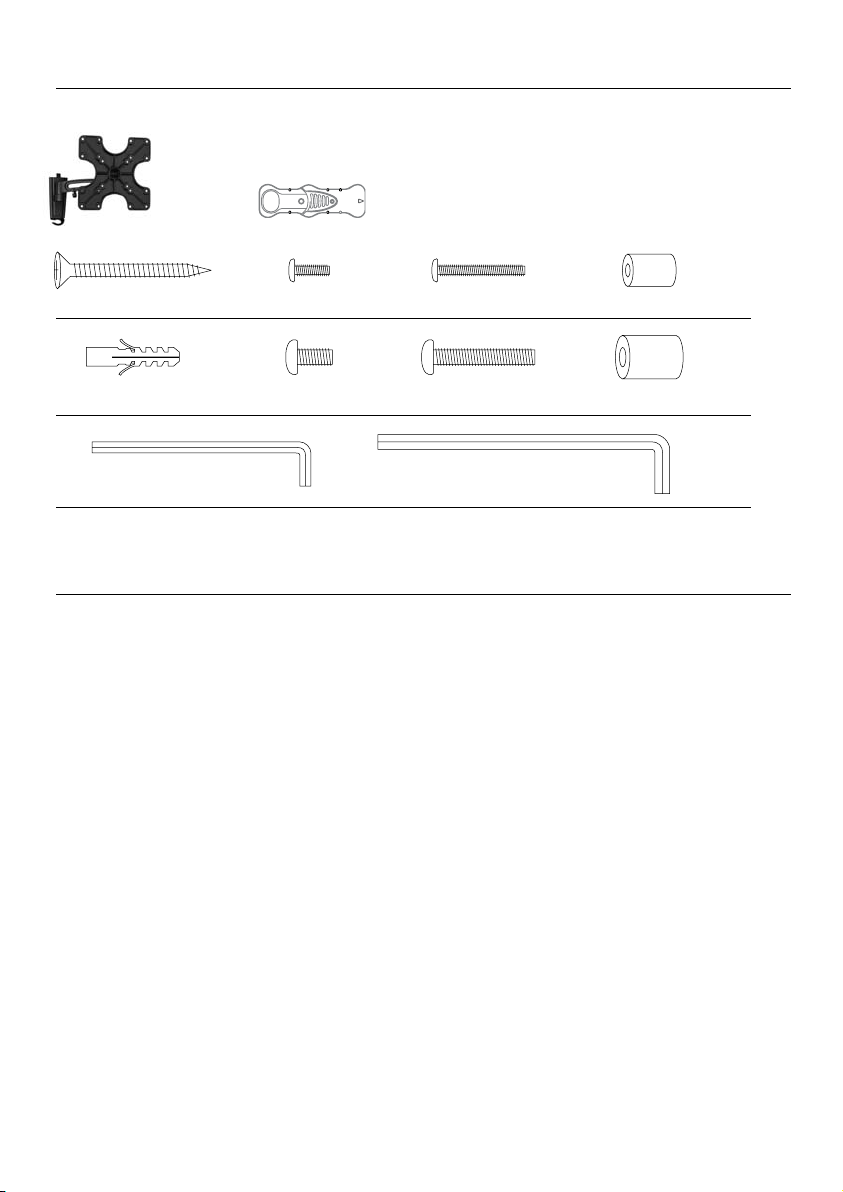
2.1 What’s in the box.
Wall mount Stud finder
(A) Drywall screw x2 (C) M4 x 12 Bolt x4 (E) M4 x 30 Bolt x4 (G) Small spacer x4
(B) Concrete anchor x2 (D) M6 x 12 Bolt x4 (F) M6 x 35 Bolt x4 (H) Large spacer x4
(I) 3mm Allen key x1 (J) 4mm Allen key x1
2.2 What you’ll also need.
• Phillips head screw driver
• Electric or portable drill
• Stud finder and 1/8˝ (3 mm) drill bit for drywall installation
• 5/16˝ (8 mm) masonry bit for concrete installation
3 Installing your wall mount
In this chapter, the basic steps to get you started
are described.
B Warning
Carefully read the safety precautions
in “Section 1 Important” before you
install the wall mount.
3.1 Mounting the wall plate (drywall)
B Warning
For safety reasons, this LCD mount
must be secured to a wood stud. The
stud must be capable of supporting
the combined weight of the mount
and display.
See enclosed mounting template for
1
diagram and guide of how to mount
properly on the wall.
Using a stud finder, locate and mark the
2
stud for securing the mount (make sure
your mark is in the center of the stud).
You can use your own stud finder or the
one included in the hardware kit.
Note: Once stud has been located you will
need to verify with a hammer and a nail
A) Simply place the nail over your mark on
the wall and tap in with hammer. If the
nail encounters resistance and is secure
in wall you have verified a stud location.
B) If it just pushes through with no
resistance you will need to start over
and locate the stud.
Using the enclosed mounting template,
3
place the diagram against the wall and mark
two locations (top and bottom) on the wall
where the mount is to be installed. Be sure
to use the center of the stud.
With the help of another person, place the
4
mount against the wall and level it using the
bubble guide.
While another person holds the mount
5
in place, mark two locations (top and
bottom) on the wall where the mount is
to be installed. Be sure to use the center of
the stud. (these marks should line up with
the ones made in step 3 above using the
template).
6 Set the mount aside and drill a 1/8” (3mm)
pilot hole at each marked location.
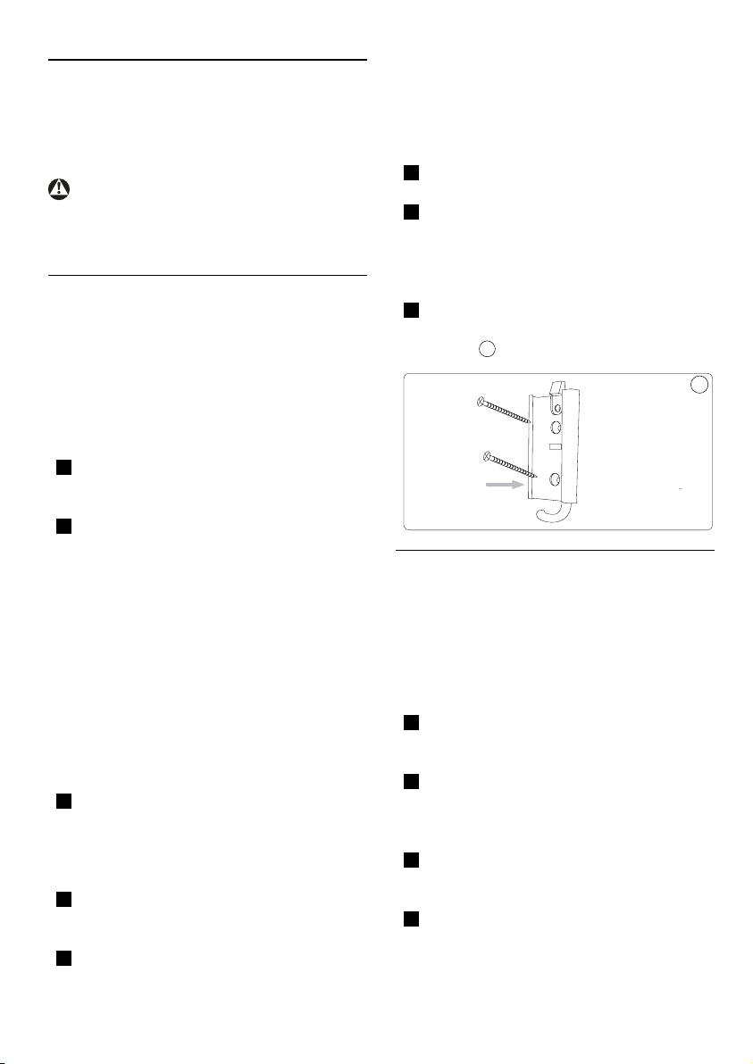
7 Place the mount back against the wall
and secure it using the wood screws (A)
provided. Do not over-tighten these screws
and do not release the mount until all
screws are in place.
8 Once both wood screws are in place you
must tighten each one. Be sure not to over
tighten.
1
3.2 Mounting the wall plate
(concrete/brick installation)
B Warning
For safety reasons, the concrete wall
must be capable of supporting the
combined weight of the mount and
display.
See enclosed mounting template for
1
diagram and guide of how to mount
properly on the wall.
Using the enclosed mounting template,
2
place the diagram against the wall and mark
two locations on the wall where the mount
is to be Installed.
With the help of another person, place the
3
mount against the wall and level it using the
bubble guide.
While another person holds the mount
4
in place, mark two locations on the wall
where the mount is to be installed.
1
5
6
5 Set the mount aside and drill a 5/16” (8mm)
6SDFHU*RU+
2QO\LIXVLQJ(RU)
%ROW&'(RU)
pilot hole at each marked location. Remove
any excess dust from the holes.
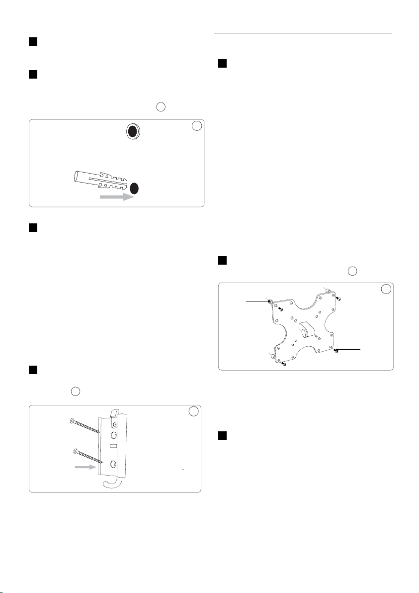
6 Insert a concrete anchor (B) into each hole
so that it is flush with the concrete surface.
A hammer can be used to lightly tap the
anchors into place if necessary.
7 Place the mount back against the wall
2
2
and secure it using the wood screws (A)
provided. Do not over-tighten these screws
and do not release the mount until all
screws are in place.
3.3 Attach the mount to your display
1 Determine the proper length of bolt for
attaching the mount to your display by
examining the back of the display:
a) If your display has a flat back, you will
use one of the shorter bolts from the
hardware kit (C or D). Carefully test each
of the shorter bolts with your display to
determine the correct diameter to use.
b) If the back of your display is curved or
recessed, or if there are any obstructions
preventing the mount from resting flat
against the back, you will use one of the
longer bolts (E or F) along with a spacer (G
or H). Carefully test each of the longer bolts
with your display to determine the correct
diameter to use. Use the small spacer (G)
with the M4 x 30 bolts (E) and the large
spacer (H) with the M6 x 35 bolts (F).
Attach the mount to your display using the
2
hardware determined in Step 1.
4
D Note
If the concrete wall is covered
by a layer of plaster or drywall,
the concrete anchor must pass
completely through the layer to rest
ush with the concrete surface.
8 Once both wood screws are in place you
must tighten each one. Be sure not to over
tighten. 3
E Tip
3
To avoid damage to your display, do
not over-tighten these bolts
Ensure all 4 bolts are used.
3
D Note
For safety reasons it is required that
all 4 bolts are used when mounting
your TV.
4
 Loading...