

Page 1
1 What is in the box
Note
Make sure you have all t hese i tems in •
the box . Cont act your dealer fo r any
missi ng or damaged i tems .
Plastic wall anchor x 2
Screw mount x 2
Movable mount x 1
Fixing mount x 1
Fixing knob x 1
M5 mounting screw x 2
Tools that are needed but not
included:
Drill•
9/64” drill bit•
Philips head screwdriver•
Hammer•
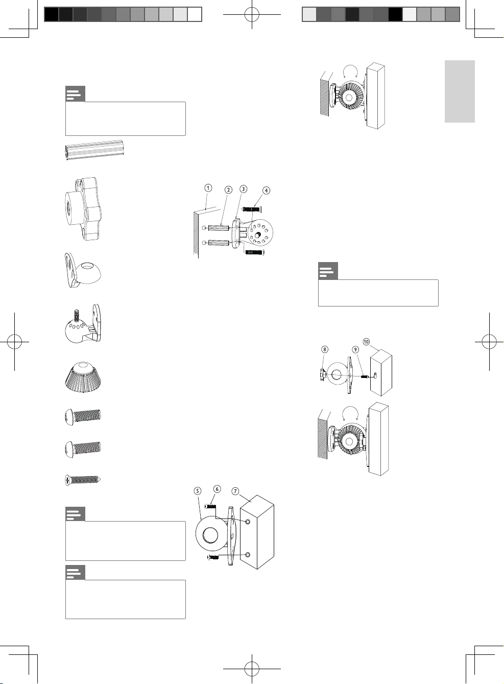
2 Assembly
instructions
1 Drill two holes in the wall. The
size of the holes need to be
slightly smaller than the plastic wall
anchors. The distance bet ween
the two holes must be the same
dist ance a s the two holes on the
fi xing mount.
2 Punch the pla stic wall anchors into
the two holes on the wall.
3 Ensure that the two holes on the
fi xing mount point at the plastic
wall anchors.
4 Put the long screws through the
fi xing mount into the plastic wall
anchors.
T here are two ways to assemble
the rest of your items. Check the
design of the speake r holes and
select a sui table way to fi x your
speaker.
5 Ensur e that the two outside holes
of the movable mount point at t he
speaker holes.
6 Put two M5 (or M6) mounting
screws through the two outside
holes of the movable mount into
the speaker.
7 Ensure the ends of the mounting
screws are fi xed tightly into the
speaker. Place the fi xing knob on
top. Adjust the movable mount
to the desired angle. Then tighten
the lock of the fi xing knob until i t
stops.
Note
In the above case, the screw mount •
is not needed.
For speakers with one hole at
the back:
English
M6 mounting screw x 2
Long screw x 2
Note
Two types of mounting screws (M5 and •
M6) are s upplied bu t only one type
is needed. Check the desi gn of your
speaker hol es fi rst.
Note
The items described are the quantity •
su pp li ed per un it pa ck . For SQ B1111
and SQB1131, 2 packs and 5 packs are
supplied in t he package respectively.
For speakers with two holes at
the back:
8 Ensur e that the scr ew mount
point s at the centr al hole of the
movable mount.
9 Put the M5 (or M6) mounting
screw through the centr al hole of
the movable mount into the screw
mount.
10 Ensure the head of the mount-
ing screw is fi xed tightly into the
speaker. Place the fi xing knob on
top. Adjust the movable mount
to the desire angle . Then tighten
the lock of the fi xing knob until i t
stops.
1SQB1111 / SQB1131
A5_SQB1111_indesign_updatedDec12.indd 1A5_SQB1111_indesign_updatedDec12.indd 1 2008-12-17 2:49:34 PM2008-12-17 2:49:34 PM
Page 2
Contenido de la caja
Nota
Aseg úres e de que la caja incluye todos •
los ele mentos siguientes. Póngase
en cont acto con el distr ibui dor si
falt a algú n elemento o s i alguno est á
dañado.
2 anclajes de plástico para pared
2 tuercas de montaje de rosca
1 sopor te de montaje móvil
1 sopor te de montaje fi jo
1 rueda de fi jación
2 tornillos M5
2 tornillos M6
2 tornillos largos
Nota
Se incl uyen dos tipos de tor nillos (M5 •
y M6), per o sólo se neces ita un tipo.
Compruebe pri mero el cali bre de los
orifi cios de los altavoces.
Nota
En la descripción de los elementos •
aparece la ca ntidad que se incluye por
pa qu ete . P ar a l os mo del os SQ B1111 y
SQB1131, se incluyen 2 y 5 pa quetes
respectivam ente en el embalaje.
Herramientas necesarias (no incluidas):
Ta lad ro•
Broca 9/6 4"•
Destornillador para tornillos de •
cabeza Phillips
Mar tillo•
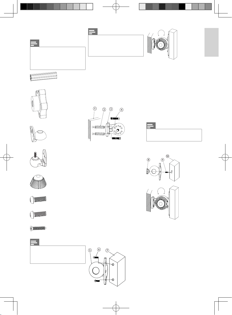
2 Instrucciones de
montaje
1 Perfore dos orifi cios en la pared.
El tamaño de los orifi cios debe
ser ligeramente infer ior al de los
anclajes de plástico para par ed.
La dis tancia entre los dos orifi cios
debe ser la misma que la exis tente
entre los dos orifi cios del sopor te
de montaje fi jo.
2 Introduzca los anclajes de plástico
en los dos orifi cios de la pared.
3 Asegúrese de que los dos or ifi cios
del sopor te de montaje fi jo estén
orientados hacia los anclajes de
plástico para pared.
4 Pase los tornillos largos a través
del sopor te de montaje fi jo e
introdúzcalos en los anclajes de
plástico.
Hay dos for mas de mont ar el resto
de los elementos. Compr uebe
el calibre de los orifi cios de los
altavoces y elija la forma adecuada
de fi jar el alt avoz.
Para altavoces con dos orifi cios
en la parte posterior:
5 Asegúrese de que los dos or ifi cios
exteriores del soporte de montaje
móvil estén orientados hacia los
orifi cios de los altavoces.
6 Inserte los dos tornillos M5 (o
M6) a través de los dos orifi cios
exteriores del soporte de montaje
móvil en el altavoz.
7 Asegúrese de que los extremos
de los tornillos estén bien fi jados
en el altavoz. Coloque la rueda de
fi jación en la parte superior. Ajuste
el soporte de montaje móvil en el
ángulo que desee. Luego, apriete
el bloqueo de la rueda de fi jación
hasta su límite .
Nota
No se necesit a tuerca de montaje de •
rosca para el caso anterior.
Para altavoces con un solo
orifi cio en la parte posterior:
8 Asegúrese de que la tuerca de
montaje de rosca esté or ientada
hacia el orifi cio central del sopor te
de montaje móvil.
9 Inserte el tornillo M5 (o M6)
a través del orifi cio central del
sopor te de mont aje móvil en la
tuerca de montaje de rosca.
10 Asegúrese de que la tue rca de
montaje de rosca esté bien fi jada
en el altavoz. Coloque la rueda de
fi jación en la parte superior. Ajuste
el soporte de montaje móvil en el
ángulo que desee. Luego, apriete
el bloqueo de la rueda de fi jación
hasta su límite .
Español
2SQB1111 / SQB1131
A5_SQB1111_indesign_updatedDec12.indd 2A5_SQB1111_indesign_updatedDec12.indd 2 2008-12-17 2:49:44 PM2008-12-17 2:49:44 PM
 Loading...