

Philips SQB1111/17, SQB1111, SQB1131 User Manual
English
1SQB1111 / SQB1131
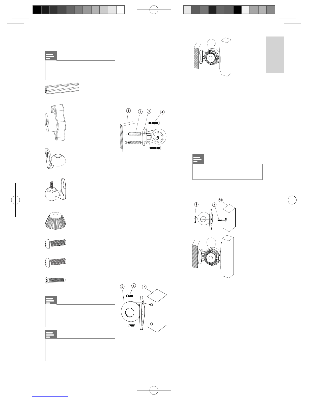
1 What is in the box
Note
Make sure you have all these items in •
the box. Contact your dealer for any
missing or damaged items.
Plastic wall anchor x 2
Screw mount x 2
Movable mount x 1
Fixing mount x 1
Fixing knob x 1
M5 mounting screw x 2
M6 mounting screw x 2
Long screw x 2
Note
Two types of mounting screws (M5 and •
M6) are supplied but only one type
is needed. Check the design of your
speaker holes fi rst.
Note
The items described are the quantity •
su ppli ed p er u nit pack . Fo r SQ B1111
and SQB1131, 2 packs and 5 packs are
supplied in the package respectively.
Tools that are needed but not
included:
Drill•
9/64” drill bit•
Philips head screwdriver•
Hammer•
2 Assembly
instructions
1 Drill two holes in the wall. The
size of the holes need to be
slightly smaller than the plastic wall
anchors. The distance between
the two holes must be the same
distance as the two holes on the
fi xing mount.
2 Punch the plastic wall anchors into
the two holes on the wall.
3 Ensure that the two holes on the
fi xing mount point at the plastic
wall anchors.
4 Put the long screws through the
fi xing mount into the plastic wall
anchors.
There are two ways to assemble
the rest of your items. Check the
design of the speaker holes and
select a suitable way to fi x your
speaker.
For speakers with two holes at
the back:
5 Ensure that the two outside holes
of the movable mount point at the
speaker holes.
6 Put two M5 (or M6) mounting
screws through the two outside
holes of the movable mount into
the speaker.
7 Ensure the ends of the mounting
screws are fi xed tightly into the
speaker. Place the fi xing knob on
top. Adjust the movable mount
to the desired angle. Then tighten
the lock of the fi xing knob until it
stops.
Note
In the above case, the screw mount •
is not needed.
For speakers with one hole at
the back:
8 Ensure that the screw mount
points at the central hole of the
movable mount.
9 Put the M5 (or M6) mounting
screw through the centr al hole of
the movable mount into the screw
mount.
10 Ensure the head of the mount-
ing screw is fi xed tightly into the
speaker. Place the fi xing knob on
top. Adjust the movable mount
to the desire angle. Then tighten
the lock of the fi xing knob until it
stops.
A5_SQB1111_indesign_updatedDec12.indd 1A5_SQB1111_indesign_updatedDec12.indd 1 2008-12-17 2:49:34 PM2008-12-17 2:49:34 PM
2SQB1111 / SQB1131
Español
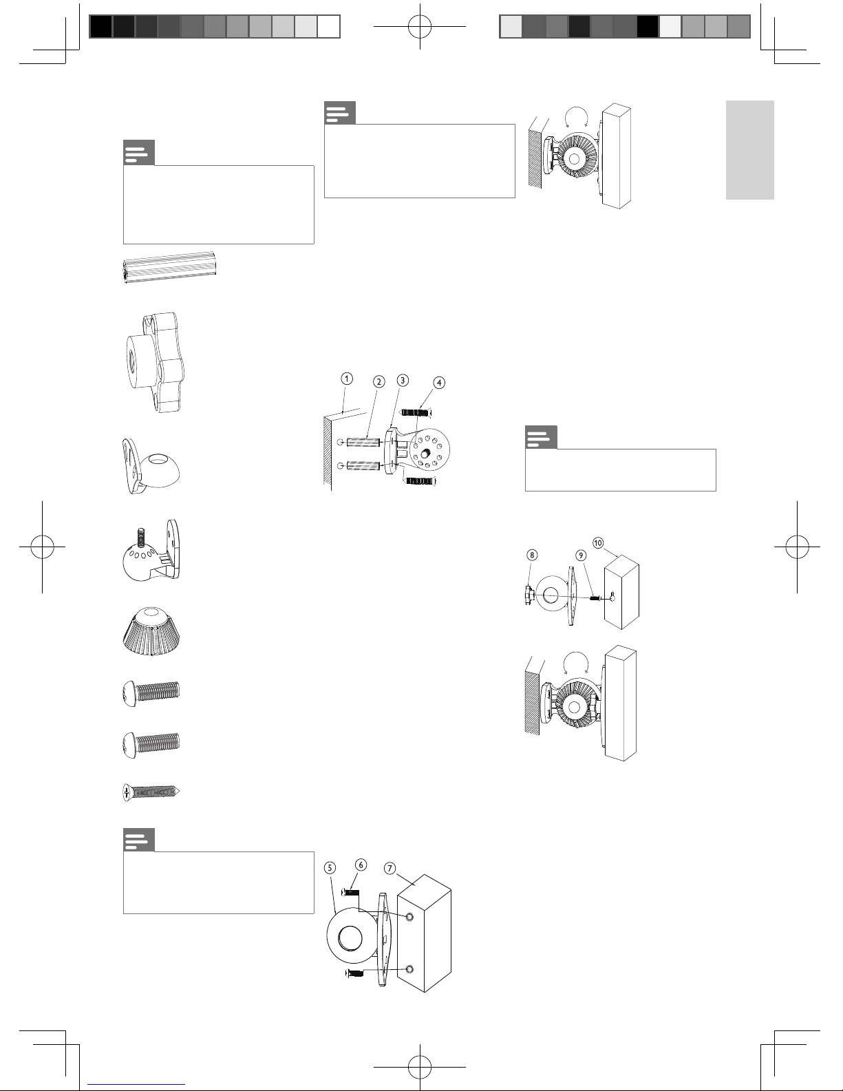
Contenido de la caja
Nota
Asegúrese de que la caja incluye todos •
los elementos siguientes. Póngase
en contac to con el dis tr ibuidor si
falta algún elemento o si alguno está
dañado.
2 anclajes de plástico para pared
2 tuercas de montaje de rosca
1 sopor te de montaje móvil
1 sopor te de montaje fi jo
1 rueda de fi jación
2 tornillos M5
2 tornillos M6
2 tornillos largos
Nota
Se incluyen dos tipos de tornillos (M5 •
y M6), pero sólo se necesi ta un tipo.
Compruebe primero el calibr e de los
orifi cios de los altavoces.
Nota
En la descripción de los elementos •
aparece la cantidad que se incluye por
pa quet e . P ar a l os m ode l os SQB1111 y
SQB1131, se incluyen 2 y 5 paquetes
respectivamente en el embalaje.
Herramientas necesarias (no incluidas):
Ta lad ro•
Broca 9/64"•
Destornillador para tornillos de •
cabeza Phillips
Mar tillo•
2 Instrucciones de
montaje
1 Perfore dos orifi cios en la pared.
El tamaño de los orifi cios debe
ser ligeramente inferior al de los
anclajes de plástico para pared.
La distancia entre los dos or ifi cios
debe ser la misma que la existente
entre los dos orifi cios del sopor te
de montaje fi jo.
2 Introduzca los anclajes de plástico
en los dos orifi cios de la pared.
3 Asegúrese de que los dos or ifi cios
del sopor te de montaje fi jo estén
orientados hacia los anclajes de
plástico para pared.
4 Pase los tor nillos largos a través
del sopor te de montaje fi jo e
introdúzcalos en los anclajes de
plástico.
Hay dos formas de montar el resto
de los elementos. Compr uebe
el calibre de los orifi cios de los
altavoces y elija la for ma adecuada
de fi jar el altavoz.
Para altavoces con dos orifi cios
en la parte posterior:
5 Asegúrese de que los dos or ifi cios
exteriores del sopor te de montaje
móvil estén orientados hacia los
orifi cios de los altavoces.
6 Inserte los dos tornillos M5 (o
M6) a través de los dos orifi cios
exteriores del sopor te de montaje
móvil en el altavoz.
7 Asegúrese de que los extremos
de los tornillos estén bien fi jados
en el altavoz. Coloque la rueda de
fi jación en la par te superior. Ajuste
el sopor te de montaje móvil en el
ángulo que desee. Luego, apriete
el bloqueo de la rueda de fi jación
hasta su límite.
Nota
No se necesita tuerca de montaje de •
rosca para el caso anterior.
Para altavoces con un solo
orifi cio en la parte posterior:
8 Asegúrese de que la tuerca de
montaje de rosca esté orientada
hacia el orifi cio central del sopor te
de montaje móvil.
9 Inserte el tornillo M5 (o M6)
a través del orifi cio central del
soporte de montaje móvil en la
tuerca de montaje de rosca.
10 Asegúrese de que la tuerca de
montaje de rosca esté bien fi jada
en el altavoz. Coloque la rueda de
fi jación en la par te superior. Ajuste
el sopor te de montaje móvil en el
ángulo que desee. Luego, apriete
el bloqueo de la rueda de fi jación
hasta su límite.
A5_SQB1111_indesign_updatedDec12.indd 2A5_SQB1111_indesign_updatedDec12.indd 2 2008-12-17 2:49:44 PM2008-12-17 2:49:44 PM
 Loading...