

Page 1
Philips
Communication &
Security Systems
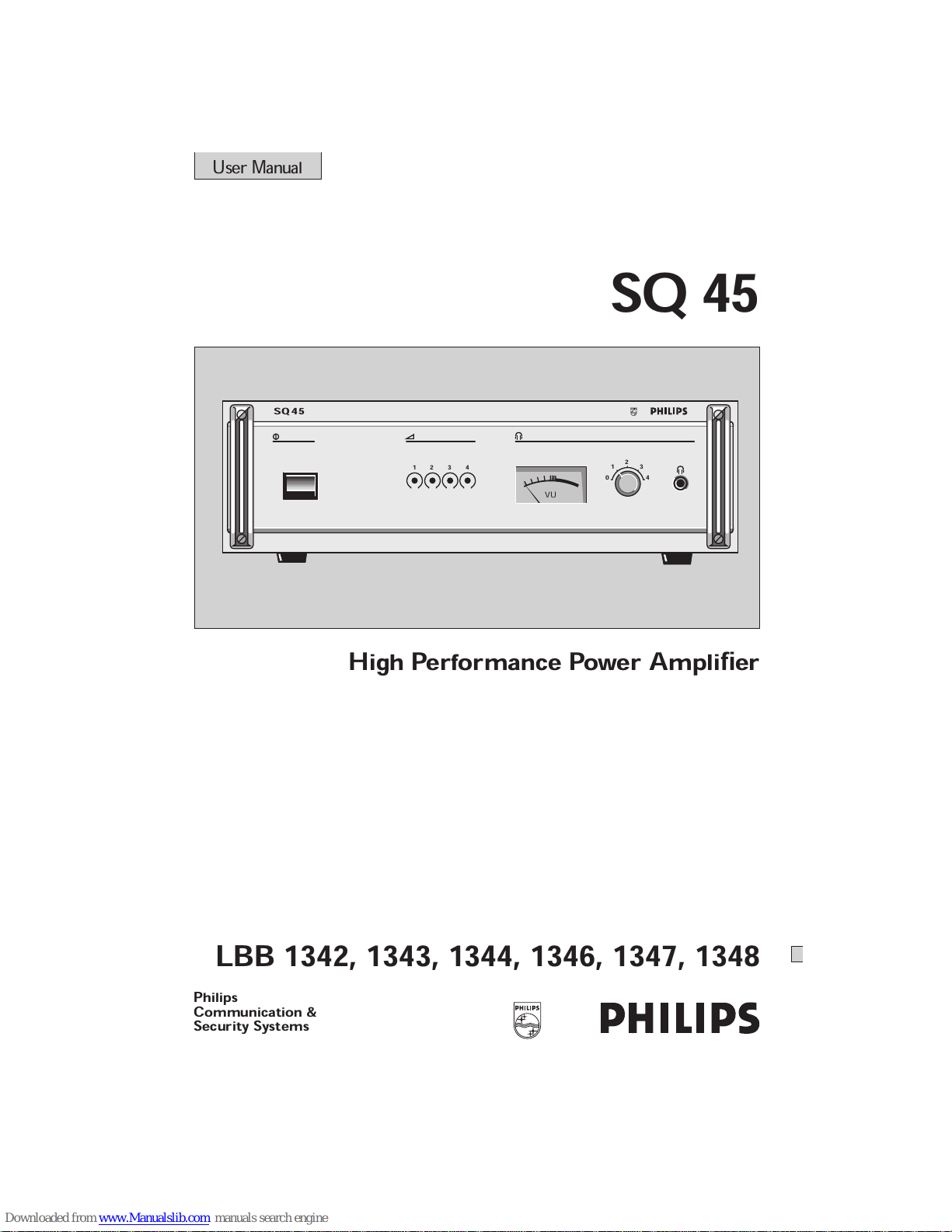
SQ 45
High Performance Power Amplifier
0
1
2
3
4
1 2 3 4
VU
SQ 45
LBB 1342, 1343, 1344, 1346, 1347, 1348
User Manual
Page 2
ENGLISH
Instructions for use page 1
TABLE OF CONTENTS
1 Introduction page 1
2 Installation 2
3 Controls 5
6 Technical data 6
Page 3
0
1
2
3
4
1 2 3 4
VU
SQ 45
1 2 3 4 5
2
1
3
4
6
7
8
9
10
11
12
1
2
3
S 1
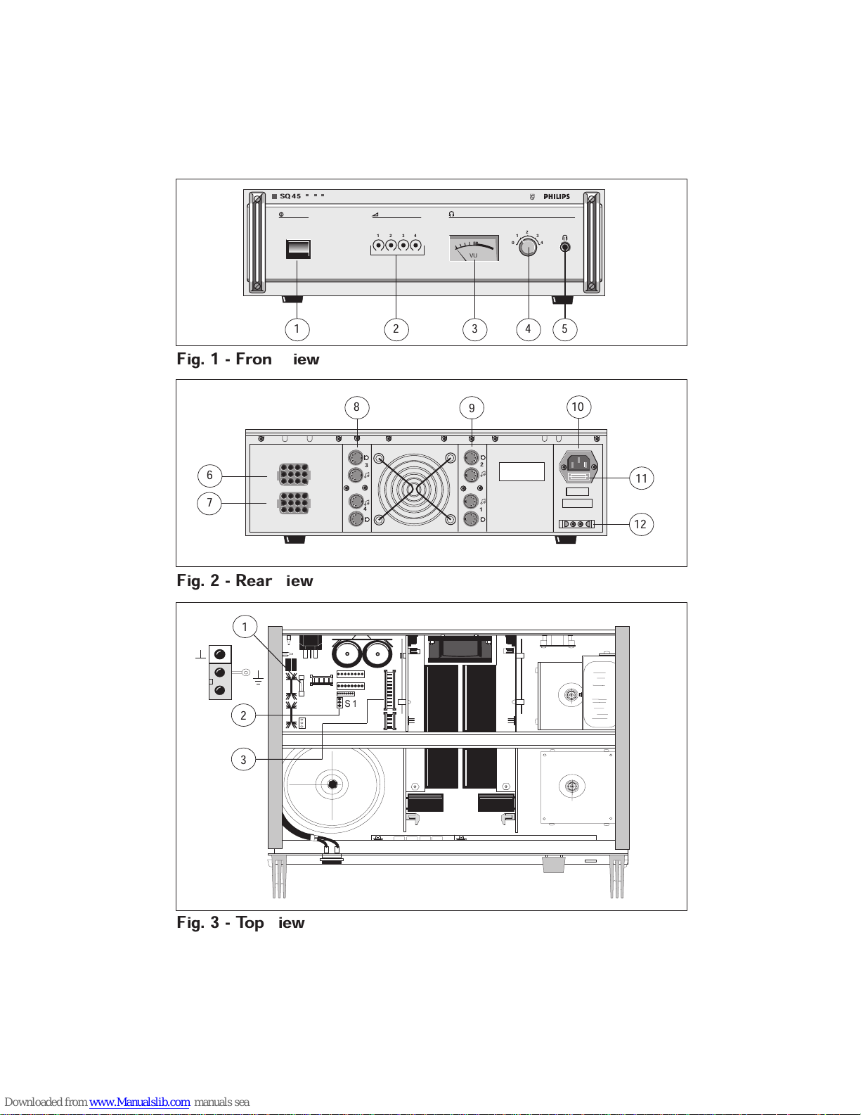
Fig. 1 - Front view
Fig. 2 - Rear view
Fig. 3 - Top view
Page 4
220V - 230V
240V
127V 110V
RED
GRN
BLK
YEL
BLUE
BRN
RED
GRN
BLK
YEL
BLUE
BRN
RED RED
GRN
GRN
BLK
BLK
YEL
YEL
BLUE
BLUE
BRN
BRN
0V + 48 V DC Emergency
battery supply
Remote switch
Open = DC power ON
Closed = DC power OFF
CALL
MUSIC
1
2
3
4
5
100V
70V
50V
0V
0V
0V
TEST INPUT
TEST INPUT
3
5
2
4
1
|
|
|
|
|
|
|
|
|
|
1
2
3
4
48V
MAINS
DC
POWER
+
-
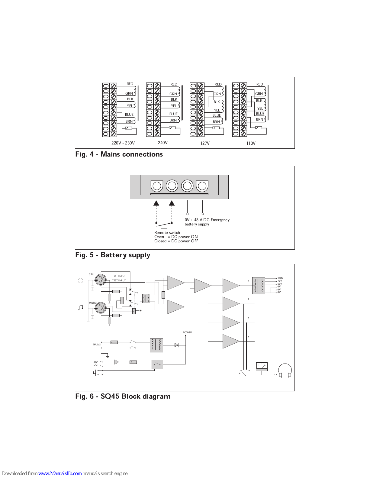
Fig. 4 - Mains connections
Fig. 5 - Battery supply
Fig. 6 - SQ45 Block diagram
Page 5
1
ENGLISH
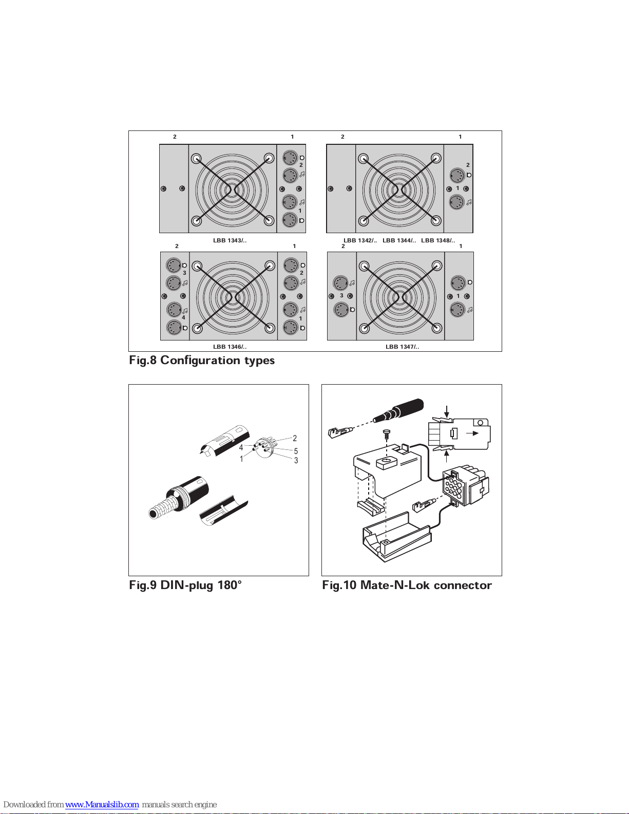
The following list gives the amplifier
configurations (see fig.8) available in the
Power Amplifiers series 100, 70 and 50 V
output:
■
LBB 1342/40 1 x 100 Watt
■
LBB 1343/40 2 x 100 Watt
■
LBB 1344/40 1 x 200 Watt
■
LBB 1346/40 4 x 100 Watt
■
LBB 1347/40 2 x 200 Watt
■
LBB 1348/40 1 x 400 Watt
Illustrations are printed on the inside of the
two-fold-out cover pages.
A mounting kit for table top version is
available under type nr. LBB 1329/30
1 INTRODUCTION
The SQ 45 range of high performance audio
power amplifiers have been designed for
smooth operation in professional Public
Address projects. Ease of installation, along
with good service accessibility and reliability
have been optimized in their design.
The mechanical housing for the range of
SQ 45 amplifiers has been designed to
accommodate up to a maximum of four
individual amplifiers in a single housing,
using a common power supply, therefore
saving both cost and space.
Because of the SQ 45 mechanical housing, a
number of configurations are available to suit
a variety of application needs. The units can
be easily mounted into 19” racks.
Each individual amplifier has two balanced
audio inputs:
■
‘music’ input, with adjustable pre-set level
control, for (continuous) back-ground
music.
■
‘priority’ input with fixed input level for
(occasional) paging and other calls.
The ‘music’ input is normally active until a
call is made, at which time the in-built relay
switches the amplifier to the ‘priority’ input,
overriding the music signal, and its volume
setting. When the call is finished the relay
switches the amplifier back to the music
input and the music signal resumes at its
normal level. The change over from one
input to the other can be controlled
remotely.
An electronically balanced ‘test’ input is
provided, into which an in- audible signal
may be injected. This signal is sampled at
the output to provide continuous
Page 6
2
monitoring of correct amplifier functioning.
Extra equipment must be used to sample the
signal; e.g The Amplifier Surveillance Board
(ASB) from the SM 40 range may be used.
The outputs may be tapped at three different
voltages (100, 70 and 50 V) from the 100 V
output transformer.
Alignment and monitoring are accomplished
via a four position selector switch for
monitoring individual amplifiers via the VU
meter and headphones.
The unit is fitted with an emergency
48 V DC battery supply, which will
automatically power the unit in the event of
a mains failure, or if there is a significant
drop in the mains supply.
2 INSTALLATION
2.1 Mains supply voltage
The unit as supplied is suitable for mains
voltages of 220 - 230 V AC. For adaption to
mains voltages of 110, 127 and 240 V, the
required voltage has to be set accordingly. To
change the voltage, unplug the long grey
coloured screw connector from its connector
block (fig. 3.3), and rewire it for the
appropriate voltage (fig. 4). Push the
connector block firmly back into its place.
For mains voltages of 110 V and 127 V, the
4 amp (T) mains fuse built into the standard
“Europlug” has to be replaced by one with a
value of 8 amp (T) (see fig. 2 10 and 2.11).
To remove the mains fuse, first remove the
mains power lead from the socket at the rear
of the unit. Carefully insert a medium sized
screwdriver under the fuse cover’s small lip
(nearest the socket pins), and gently twist the
screwdriver to lever the fuse holder out.
A self-restoring thermal cut-out operates on
the primary winding of the mains
transformer.
WARNING:
When due to excessive temperature, the
thermal cut-out shuts down the amplifier
although the full mains voltage will still be
present inside the unit.
A suitable earthed AC mains distribution
socket should be provided inside the 19”
rack to provide power for the amplifiers. The
unit is supplied with a 2.5 m long mains
lead, terminated with a standard IEC two
pole earthed mains plug. In some countries it
will be necessary to replace this plug with
one of a local standard type.
Page 7
3
A replacement plug must be wired as follows:
earth - green/yellow
neutral - blue
live - brown
WARNING:
This apparatus must be earthed.
2.2 Emergency power supply 48 Volt
In situations where the mains power supply
is unreliable an emergency 48 V battery
supply may be used. This supply will
automatically be switched in whenever the
mains power fails. A Mate-N-Lok supply
socket is provided to allow the 48 V DC
battery supply to be connected (fig. 2.12).
Details of the connector are shown in fig. 5
and should be wired accordingly. For use in
special applications, a manual on-off switch
can be connected enabling the 48 V DC
power supply to be switched on and off as
and when required.
The value of the 48 V DC fuse (fig. 3.1) is
10 amp.
2.3 Grounding and earth loops
On delivery the electrical and mechanical
earths of the unit are interconnected. When
two or more units are used in a system, it is
necessary to ensure that earth loops are not
introduced by earth wiring. In this case, the
electrical earths of all units should be linked
together via e.g. points 2 of DIN connector,
then joined by one wire link to the
mechanical earth on one unit only. To
disconnect the electrical and mechanical
earths, jumper S1 (fig. 3.2) must be
positioned as shown or removed.
2.4 Input connections
Each of the amplifiers in the unit is provided
with three inputs: ‘priority’, ‘music’ and ‘test’.
The connections for these inputs, and the
wiring for the remotely controlled selection
between the ‘priority’ and the ‘music’ input,
is made via two, 5-pole 180° DIN-type
sockets per amplifier.
The pins of the corresponding plugs (fig. 6)
are to be connected as described next:
2.5 Music input (fig. 6)
pin 1 - music signal, live
pin 2 - music signal, screen
pin 3 - music signal, live (return)
pin 4 - not connected
Pin 5 - input selection*
* To allow remote control of input signal
selection:
Music input - pins 2 & 5 linked
(relay activated)
Priority input - pins 2 & 5 open
2.6 Priority and Test input (fig. 6)
pin 1 - call signal, live
pin 2 - call signal, screen
pin 3 - call signal, live (return)
pin 4 - test signal, live
pin 5 - test signal, live (return)
The ‘test’ input (pins 4 and 5) is active under
both conditions.
NOTE:
The ‘test’ input is provided for ultimate use
with the SM 40 microcomputer controlled
surveillance system.
Page 8
4
2.7 Input sensitivity adjustment
The ‘priority’ input sensitivity is optimised
for use with the SM 40 or SM 30 system,
and pre-set at 1 V on delivery. Improving the
sensitivity to 0.5 V is simply a matter of
removing 1 or up to 4 jumpers S3 (S103)
located on the printed circuit board(s) of the
amplifier. The number of jumpers to be
removed depends on the configuration of the
amplifer. For location details of the jumpers
refer to Service Information code no.
4822 861 05034.
The ‘music’ input sensitivity is adjustable
between 0.5 and 10 V to cope with output
levels from external or domestic music
sources, e.g. CD player, radio tuner, and
cassette player etc.
2.8 Parallel connection of inputs
The pre-amplifier output of, for example, a
mixing amplifier, may be connected to the
input of this amplifier, and to the inputs of
several other power amplifiers. Public
Address systems of practically any wattage
can be built by using this method of
connection.
2.9 Loudspeaker connections
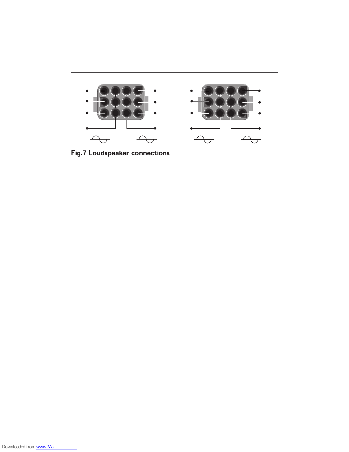
On delivery the amplifier is supplied with a
small plastic bag containing two 12-pole
Mate-N-Lok blocks, complete with contact
pin ejector tool (fig. 10). When fitting the
contact pins to the external wiring, they may
be either soldered or crimped.
Also included in this bag are three small
plastic inserts used to cap any redundant
holes left by the sensitivity controls at the
front of the amplifier.
Mate-N-Lok sockets are mounted on the rear
panel, (fig. 2). These are provided with
corresponding plugs, and serve primarily as
transformer output connections to a variety
of loudspeakers. Socket X5 (fig. 2.6) is for
outputs of amplifiers 2 and 3. Socket X6
(fig. 2.7) is used for the outputs of amplifiers
1 and 4.
2.10 Loudspeakers for 100, 70 or 50V
systems
Loudspeakers with suitable matching
transformers can be connected in parallel
with the 100, 70 or 50 V outputs so long as
the total power does not exceed the nominal
output power rating of the amplifier.
The maximum cable length from the
amplifier to the loudspeakers can also be
determined by the amplifier output’s
maximal load capacitance (see technical
data).
100 V loudspeakers connected to the 100 V
output will consume their nominal power. If,
however,100 V loudspeakers are connected
to the 70 V output, then the loudspeakers
power consumption will be equal to one half
of their nominal rated power. This means
that twice as many loudspeakers can be
connected without overloading the amplifier.
Similarly, if 100 V loudspeakers are
connected to the 50 V output they will only
consume a quarter of their nominal power,
and an increase of up to four times as many
loudspeakers is possible.
2.11 In-phase connection of loudspeakers
Disturbing effects can occur, particularly
when loudspeakers are mounted close
together, which are caused by the
loudspeakers being connected in anti-phase.
To ensure an in-phase connection in 100 V
Page 9
5
systems, all similar loudspeaker terminals (in
most cases one terminal is marked with a red
dot) must be connected to the same wire on
the distribution cable.
2.12 Mounting the unit into a 19” rack
WARNING:
For safety reasons this unit may only be
mounted in a 19” rack with lockable top
and bottom covers, side panels, and rear
door(s), which can only be opened by
skilled technicians, and should be fitted so
that mains terminals and all live parts are
not accessible from outside the rack.
The unit may be mounted into a rack by
means of four bolts with washers, via slots in
the front panel. No further mechanical
support is necessary.
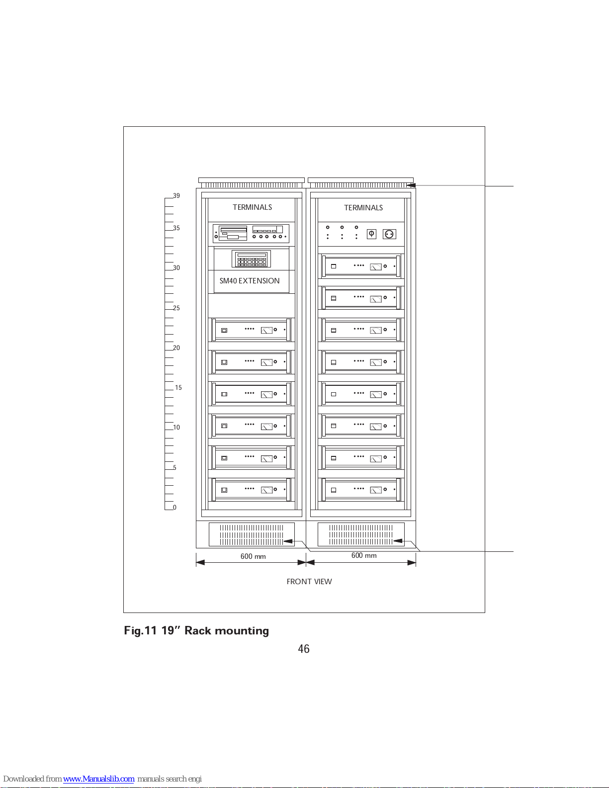
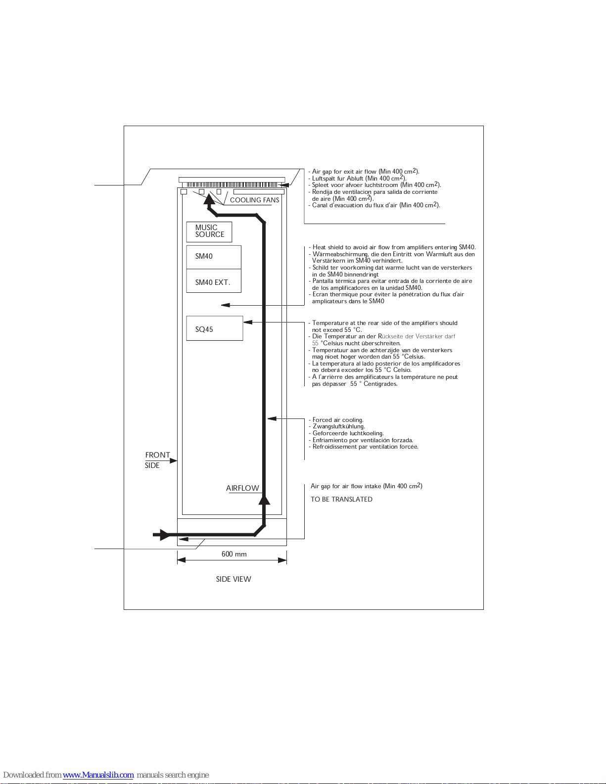
The units should be mounted with 1HE
spacing panels (fig. 11) and rack forced
cooling should be considered, especially
when the units are used continuously at full
power with music and speech (call) at an
ambient temperature of 55°C max. (acc.
IEC 65).
Mounted in a (19”) cabinet, the temperature
inside the cabinet will be valid as ambient
temperature for the amplifier. Exceeding this
temperature can cause a decrease in the
amplifiers expected life-time. Depending on
the installed power in a cabinet, a number of
precautions are advised . (Refer also to
fig. 11).
3 CONTROLS (see fig. 1)
1 Mains on/off switch.
2 Sensitivity control pre-set for ch-1, ch-2,
ch-3 and ch-4 ‘music’ inputs only.
3 Output leven VU-meter plus illuminated
scale (mains on).
4 Four position selector switch for
monitoring individual amplifier channels
via the VU-meter and headphones.
5 Headphones socket (6.3 mm standard
jack socket).
Page 10
6
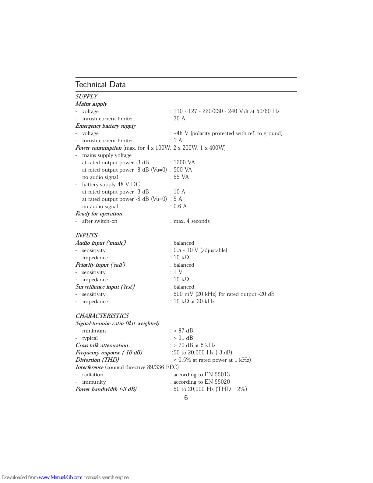
Technical Data
SUPPLY
Mains supply
- voltage : 110 - 127 - 220/230 - 240 Volt at 50/60 Hz
- inrush current limiter : 30 A
Emergency battery supply
- voltage : +48 V (polarity protected with ref. to ground)
- inrush current limiter : 1 A
Power consumption
(max. for 4 x 100W; 2 x 200W; 1 x 400W)
- mains supply voltage
at rated output power -3 dB : 1200 VA
at rated output power -8 dB (Vu=0) : 500 VA
no audio signal : 55 VA
- battery supply 48 V DC
at rated output power -3 dB : 10 A
at rated output power -8 dB (Vu=0) : 5 A
no audio signal : 0.6 A
Ready for operation
- after switch-on : max. 4 seconds
INPUTS
Audio input (‘music’)
: balanced
- sensitivity : 0.5 - 10 V (adjustable)
- impedance : 10 k
Ω
Priority input (‘call’)
: balanced
- sensitivity : 1 V
- impedance : 10 k
Ω
Surveillance input (‘test’)
: balanced
- sensitivity : 500 mV (20 kHz) for rated output -20 dB
- impedance : 10 kΩat 20 kHz
CHARACTERISTICS
Signal-to-noise ratio (flat weighted)
- minimum : > 87 dB
- typical : > 91 dB
Cross talk attenuation
: > 70 dB at 5 kHz
Frequency response (-10 dB)
::50 to 20,000 Hz (-3 dB)
Distortion (THD)
: < 0.5% at rated power at 1 kHz)
Interference
(council directive 89/336 EEC)
- radiation : according to EN 55013
- immunity : according to EN 55020
Power bandwidth (-3 dB)
: 50 to 20,000 Hz (THD = 2%)
Page 11
7
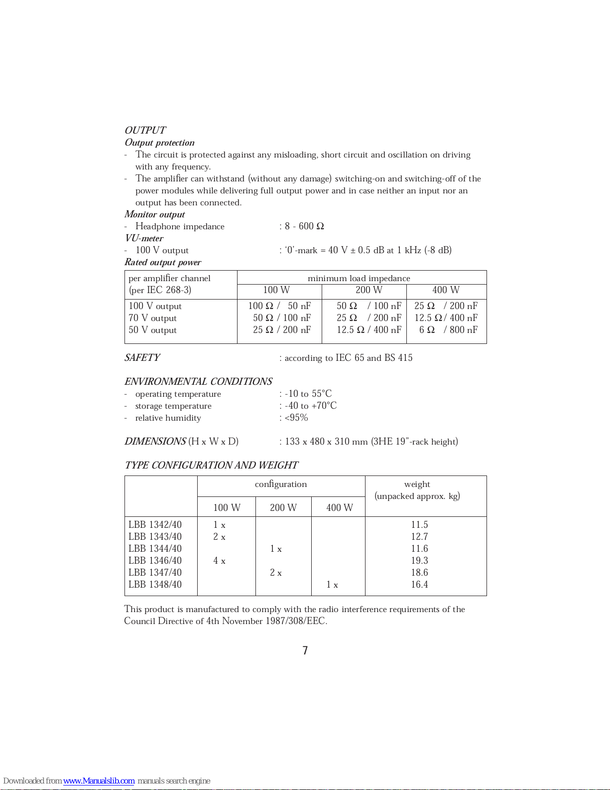
OUTPUT
Output protection
- The circuit is protected against any misloading, short circuit and oscillation on driving
with any frequency.
- The amplifier can withstand (without any damage) switching-on and switching-off of the
power modules while delivering full output power and in case neither an input nor an
output has been connected.
Monitor output
- Headphone impedance : 8 - 600
Ω
VU-meter
- 100 V output : ‘0’-mark = 40 V ± 0.5 dB at 1 kHz (-8 dB)
Rated output power
SAFETY
: according to IEC 65 and BS 415
ENVIRONMENTAL CONDITIONS
- operating temperature : -10 to 55°C
- storage temperature : -40 to +70°C
- relative humidity : <95%
DIMENSIONS
(H x W x D) : 133 x 480 x 310 mm (3HE 19”-rack height)
TYPE CONFIGURATION AND WEIGHT
This product is manufactured to comply with the radio interference requirements of the
Council Directive of 4th November 1987/308/EEC.
per amplifier channel minimum load impedance
(per IEC 268-3) 100 W 200 W 400 W
100 V output 100 Ω/ 50 nF 50 Ω/ 100 nF 25 Ω/ 200 nF
70 V output 50 Ω/ 100 nF 25 Ω/ 200 nF 12.5 Ω/ 400 nF
50 V output 25 Ω/ 200 nF 12.5 Ω/ 400 nF 6 Ω/ 800 nF
configuration weight
(unpacked approx. kg)
100 W 200 W 400 W
LBB 1342/40 1 x 11.5
LBB 1343/40 2 x 12.7
LBB 1344/40 1 x 11.6
LBB 1346/40 4 x 19.3
LBB 1347/40 2 x 18.6
LBB 1348/40 1 x 16.4
Page 12
46
0
5
10
15
20
25
30
35
39
TERMINALS
SM40 EXTENSION
TERMINALS
FRONT VIEW
600 mm
600 mm
|
|
|
|
|
|
|
|
|
|
|
|
|
|
|
|
|
|
|
|
|
|
|
|
|
|
|
|
|
|
|
|
|
|
|
|
|
|
|
|
|
|
|
|
|
|
|
|
|
|
|
|
|
|
|
|
|
|
|
|
|
|
|
|
|
|
|
|
|
|
|
|
|
|
|
|
|
|
|
|
|
|
|
|
|
|
|
|
|
|
|
|
|
|
|
|
|
|
|
|
|
|
|
|
|
|
|
|
|
|
|
|
|
|
|
|
|
|
|
|
|
|
|
|
|
|
|
|
|
|
|
|
|
|
|
|
|
|
|
|
|
|
|
|
|
|
|
|
|
|
|
|
|
|
|
|
|
|
|
|
|
|
|
|
|
|
|
|
|
|
|
|
|
|
|
|
|
|
|
|
|
|
|
|
|
|
|
|
|
|
|
|
|
|
|
|
|
|
|
|
|
|
|
|
|
|
|
|
|
|
|
|
|
|
|
|
|
|
|
|
|
|
|
|
|
|
|
|
|
|
|
|
|
|
|
|
|
|
|
|
|
|
|
|
|
|
|
|
|
|
|
|
|
|
|
|
|
|
|
|
|
|
|
|
|
|
|
|
|
|
|
|
|
|
|
|
|
|
|
|
|
|
|
|
|
|
|
|
|
|
|
|
|
|
|
|
|
|
|
|
|
|
|
|
|
|
|
|
|
|
|
|
|
|
|
|
|
|
|
|
|
|
|
|
|
|
|
|
|
|
|
|
|
|
|
|
Fig.11 19” Rack mounting
Page 13
600 mm
AIRFLOW
SIDE VIEW
FRONT
SIDE
COOLING FANS
- Air gap for exit air flow (Min 400 cm2).
- Luftspalt fur Abluft (Min 400 cm2).
- Spleet voor afvoer luchtstroom (Min 400 cm2).
- Rendija de ventilacion para salida de corriente
de aire (Min 400 cm2).
- Canal d'evacuation du flux d'air (Min 400 cm2).
- Heat shield to avoid air flow from amplifiers entering SM40.
- Wärmeabschirmung, die den Eintritt von Warmluft aus den
Verstärkern im SM40 verhindert.
- Schild ter voorkoming dat warme lucht van de versterkers
in de SM40 binnendringt
- Pantalla térmica para evitar entrada de la corriente de aire
de los amplificadores en la unidad SM40.
- Ecran thermique pour éviter la pénétration du flux d'air
amplicateurs dans le SM40
- Temperature at the rear side of the amplifiers should
not exceed 55 °C.
- Die Temperatur an der R
ückseite der Verstärker darf
55
°Celsius nucht überschreiten.
- Temperatuur aan de achterzijde van de versterkers
mag nioet hoger worden dan 55 °Celsius.
- La temperatura al lado posterior de los amplificadores
no deberá exceder los 55 °C Celsio.
- A l'arrièrre des amplificateurs la température ne peut
pas dépasser 55 ° Centigrades.
- Forced air cooling.
- Zwangsluftkühlung.
- Geforceerde luchtkoeling.
- Enfriamiento por ventilación forzada.
- Refroidissement par ventilation forcée.
SQ45
SM40 EXT.
Air gap for air flow intake (Min 400 cm2)
TO BE TRANSLATED
SM40
SOURCE
MUSIC
Page 14
100 V
X5
Channel 2
Channel 3
100 V
70 V
70 V
50 V
+
0 V
0 V
50 V
+
100 V
X6
Channel 1
Channel 4
100 V
70 V
70 V
50 V
+
0 V
0 V
50 V
+
Fig.7 Loudspeaker connections
Page 15
2
1
3
4
1
3
2
2
1
12 1
2
LBB 1343/..
LBB 1346/.. LBB 1347/..
LBB 1342/.. LBB 1344/.. LBB 1348/..
1 2 1
2
1
1
2
4
5
3
Fig.8 Configuration types
Fig.10 Mate-N-Lok connectorFig.9 DIN-plug 180°
Page 16

3922 988 33394 94-08 All specifications subject to modification without notice
 Loading...