

Page 1
sPDS-60ca
Compact power / data supply for low-voltage linear fi xtures
Page 2
sPDS-60ca
Compact power / data supply for low-voltage linear fi xtures
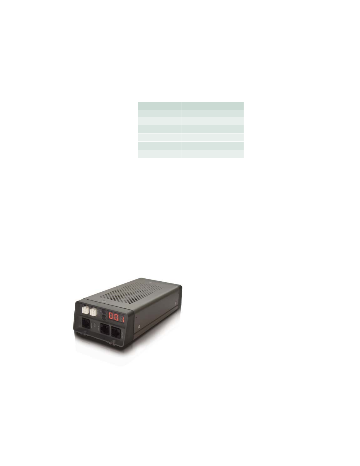
sPDS-60ca 24 V is a compact power / data supply designed for up to 30 low-voltage linear fixtures
Color Kinetics
sPDS-60ca 24 V is compatible with both
Ethernet and DMX controllers and
accommodates input voltages ranging from
100 VAC to 240 VAC. All power and data
connections are made via an external panel
for reduced installation time. Short-circuit
protection prevents failure due to incorrectly
wired fixtures.
Onboard push-button controls offer the ability
to address all connected fixtures, eliminating
need for additional addressing tools or software.
The sPDS -60ca 24 V enclosure is designed for
use in dry locations.
.
Compatible Fixtures
the
Fixture Max. Quantity
eW Flex SLX 60 nodes
iColor Flex LMX 60 nodes
iColor Cove EC 7 in 30 fi xtures
iColor Cove EC 12 in 30 fi xtures
iColor Cove QLX 6 in 30 fi xtures
iColor Cove QLX 12 in 20 fi xtures
Per sPDS-60ca 24 V
from Philips
Compact Power and Data
for Low-Voltage Linear
Installations
Provides on-board addressing
capabilities and external fixture
ports for easy installation, and
provides power, data, and short
circuit protection for up to 30 lowvoltage fixtures.
sPDS-60ca Product Guide2
Page 3
Specifi cations
Due to continuous improvements and innovat ions, specif ications may change without notice.
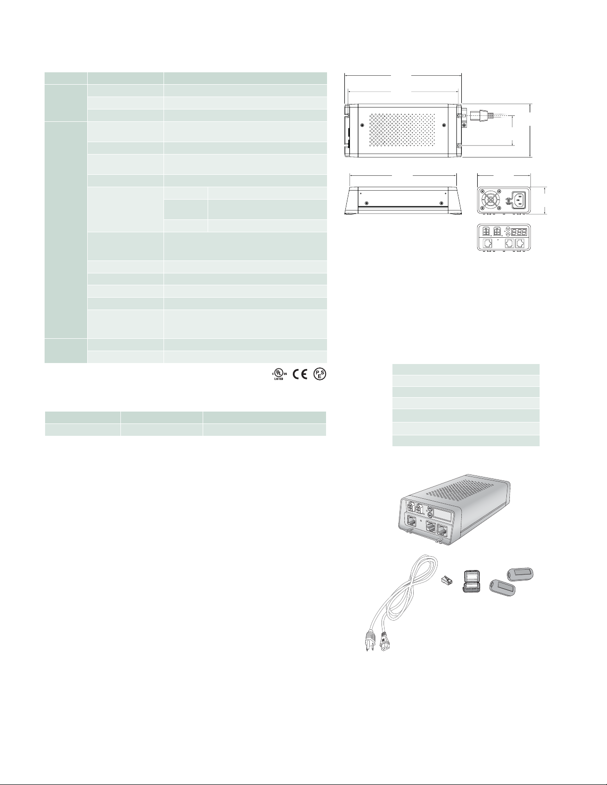
Item Specifi cation Details
Input Voltage 100 – 240 VAC, auto-switching, 50 / 60 Hz
Electrical
Maximum Input Current 1.7 A at 100 VAC, 1.5 A at 120 VAC, .75 A at 240 VAC
Power Output 24 VDC, 62 W maximum
Dimensions
(Height x Width x Depth)
2.0 x 4.0 x 8.8 in (51 x 102 x 224 mm)
Weight 2.0 lb (.91 kg)
Construction
Aluminum case with impact-resistant, injection-molded
plastic end caps, surface mount design
Finish Gray and black matte
Data RJ45 input and output connectors
ower
Physical
Connectors
P
Output
Power Input
(2) 4-pin output ports
IEC 320 receptacle type C13, locking clamp
14° – 104° F (-10° – 40° C) Operating
Temperature Ranges
14° – 122° F (-10° – 50° C) Startup
-40° – 176° F (-40° – 80° C) Storage
Humidity 0 – 95%, non-condensing
Cooling Thermostatically controlled fan
Airfl ow Top cover input, back panel output
Heat Dissipation 25% of total power input at maximum load
Philips full range of controllers, third-party DMX
Data Input
controllers, or KiNET-compatible*
third-party Ethernet
controllers
Certifi cation
and Safety
*
KiNET
Classifi cation UL Class 2 power supply
Environment Dry Location, IP20
is the Ethernet lighting protocol from Philips Color Kinetics.
Ordering Information
Item Item Number Philips 12NC
sPDS-60ca 24
V 109-000021-02 910503700106
Use Item Number when ordering in North America.
8.8 in
(224 mm)
8.3 in
(211 mm)
8.0 in
(203 mm)
4.0 in
(102 mm)
OUT 1
IN
DATA
ENET
Included in the box
sPDS-60ca 24 V power / data supply
(2) White clamp-on EMI suppression cores
Black clamp-on EMI suppression cores
DMX data terminator
IEC power cable
RJ45 terminator
Installation Instructions
2.3 in
(58 mm)
ALT
OUT 2
IN
DMX
4.0 in
(102 mm)
OUT
DMX
2.0 in
(51 mm)
ALT
OUT 2
DATA
ENET IN
DMX IN
DMX OUT
sPDS-60ca Product Guide 3
Page 4
Installation
sPDS-60ca is a power / data supply designed
lighting installations.
sPDS-60ca
uses up to 30 low-voltage fixtures from Philips Color
Kinetics and delivers 62 watts of low-voltage output via two ports. It automatically
accommodates input voltages ranging from 100 VAC to 240 VAC. On-board controls
allow you to set fixture addresses.
Owner / User Responsibilities
It is the responsibility of the contractor, installer, purchaser, owner, and user to install,
maintain, and operate
sPDS-60ca
in such a manner as to comply with all applicable
codes, state and local laws, ordinances, and regulations. Consult with the appropriate
electrical inspector to ensure compliance.
for low-voltage linear DMX and Ethernet
Plan the Installation
To streamline installation and ensure accurate confi guration, start with a layout or
a lighting design plan that shows the physical layout of the installation and identifi es
the locations of all lighting fi xtures,
cables.
DMX and Ethernet Confi gurations
sPDS-60ca
can be used in either DMX or Ethernet networks. DMX is appropriate
for relatively simple installations, or for installations in which groups of lights operate
in unison (for example, for accent lighting, perimeter lighting, or cove lighting
applications).
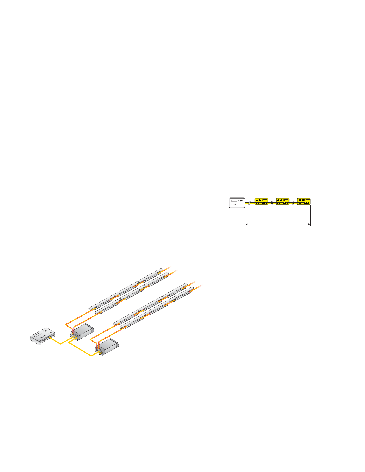
Typical DMX installations with fixtures from Philips Color Kinetics use a controller
such as iPlayer 3, a Controller Keypad for turning lights on and off and triggering light
shows, and one or more sPDS-60ca devices. sPDS-60ca devices can be connected in
series to deliver DMX data from a single controller to all connected lights. Note that
the maximum for DMX data run lengths is 1000 ft (305 m).
power / data supplie
s, controllers, switches, and
E Refer to the sPDS -60ca Installation
Instructions for specifi c warning and
caution statements.
Controller
1000 ft (305 m) Max
DMX maximum data run length
iColor Cove QLX
iPlayer 3
sPDS-60ca 24V
Typical DMX installation
sPDS-60ca Product Guide4
Page 5
328 ft (100 m) Max
Ethernet maximum data cable length
Compatible fixtures
Fixture Max. Quantity
eW Flex SLX 60 nodes
iColor Flex LMX 60 nodes
iColor Cove EC 7 in 30 fi xtures
iColor Cove EC 12 in 30 fi xtures
iColor Cove QLX 6 in 30 fi xtures
iColor Cove QLX 12 in 20 fi xtures
Included in the box
sPDS-60ca 24 V power / data supply
(2) White clamp-on EMI suppression cores
Black clamp-on EMI suppression core
DMX data Terminator
IEC power cable
RJ45 terminator
Installation Instructions
sPDS-60caController
Per sPDS-60ca 24 V
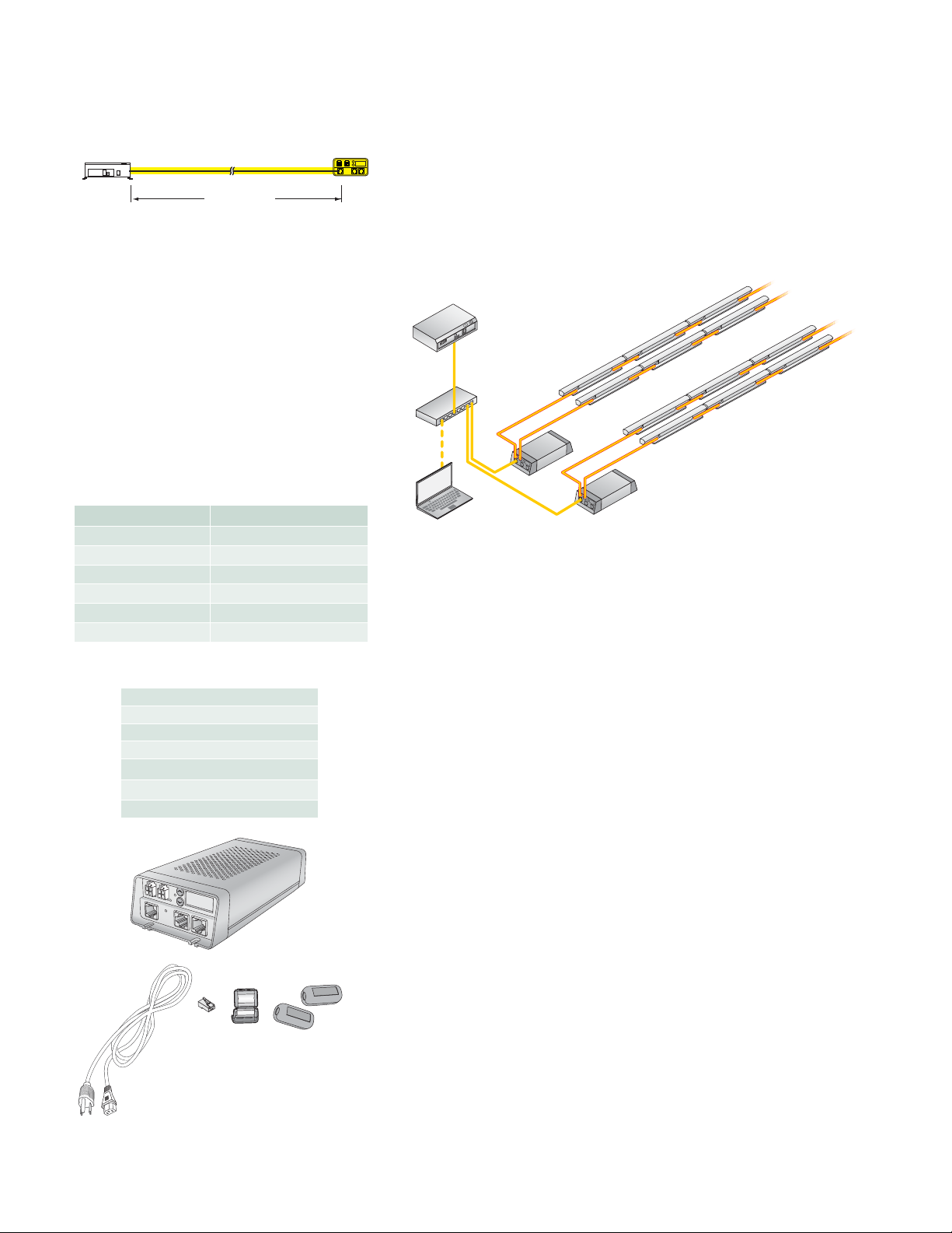
Because it is not subject to the DMX addressing limitations, Ethernet is the preferred
environment for large-scale, color-changing light shows and video displays, both of
which require large numbers of unique addresses.
Typical Ethernet installations with LED lighting fixtures from Philips Color Kinetics
use an Ethernet switch, an Ethernet controller (such as Light System Manager or
Video System Manager Pro), one or more Ethernet Controller Keypads (for light show
triggering), and one or more sPDS-60ca devices. For additional devices in a network,
use additional Ethernet switch ports. Note that in Ethernet networks, the maximum
data cable lengths are 328 ft (100 m) between Ethernet devices without a repeater (for
example, the cable between a controller and switch, or switch and sPDS-60ca).
Light
System
Manager
Ethernet
Switch
iColor Cove QLX
sPDS-60ca 24V
PC
Typical Ethernet installation
Electrical Confi guration Guidelines
Refer to the table at left for the quantities of each fi xture that you can connect per
sPDS-60ca device.
Refer to the fi xture product guides for information on electrical confi guration for
fi xtures. Each sPDS-60ca uses standard line power via an IEC inlet and power cable.
You can secure the device’s power cable using a locking clamp attached to the
housing.
sPDS-60ca should be installed in a dry location.
Inspect sPDS-60ca and Accessories
Carefully inspect the box containing the sPDS-60ca and the contents for any damage
that may have occurred in transit.
Assemble Additional Items
The following items are required to mount and connect the sPDS-60ca:
ALT
OUT 2
DATA
ENET IN
DMX IN
DMX OUT
• The included RJ45 terminator (required in DMX lighting networks)
• The included IEC power cable
• CAT 5e or better data cable, as required
• The included black magnetic EMI suppression core (for the IEC power cable)
• The included two white magnetic EMI suppression cores (for Flex strands or
fi xture leader cables)
• Power screwdriver (for mounting)
• Four screws suitable for the mounting surface
• Philips screwdriver
sPDS-60ca Product Guide 5
Page 6
Mount the sPDS-60ca
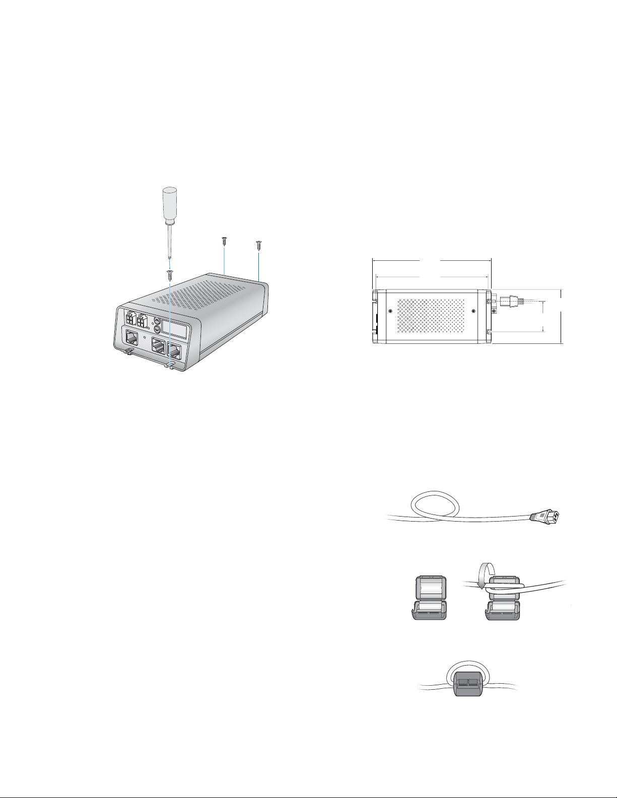
Make sure the sPDS-60ca device is powered OFF before mounting and connecting. A
power screwdriver is recommended.
1. Position the sPDS-60ca device in its designated mounting location. Make sure the
mounting location is fl at, suitable for the mounting hardware, and clear of debris
and other obstructions.
2. Using four M3.5 or #6 screws suitable for the mounting surface, secure the
sPDS-60ca device to the surface using the two mounting slots located at both
ends of the device.
ALT
OUT 2
DATA
ENET IN
DMX IN
DMX OUT
E Make sure that there is adequate
space to make all connections to the front
and rear of the device. Also, the vents at
the top and rear of the device should not
be obstructed.
E Make sure that the device is securely
attached to the mounting surface and free
of excessive vibration.
8.8 in
(224 mm)
8.3 in
(211 mm)
2.3 in
(58 mm)
4.0 in
(102 mm)
Install EMI Suppression Cores
The sPDS-60ca ships with three EMI suppression cores. These suppression cores
reduce electromagnetic noise that can interfere with other electrical equipment.
The white suppression cores are for Flex strands or fi xture leader cables. The black
suppression core is for the IEC power cable.
Before attaching the cores, make sure that each set of ferrite metal halves are secure
in their plastic housing.
1. Attach the black suppression core to the power cable:
• Near the end of the cable that connects to the power / data supply, coil the
IEC power cable into a small loop.
• Place the section of the loop where the cord is doubled into the suppression
core. Be sure the cord is securely in the core’s middle.
• Snap the core shut around the doubled cord.
2. Attach a white suppression core to the fi xture strand or leader cable attached
to port 1.
• Near the connection to the power / data supply, coil the strand or cable into
a small loop.
• Place the section of the loop where the cord is doubled into the suppression
core. Be sure the cord is securely in the core’s middle.
• Snap the core shut.
3. Repeat step 2 for the second white suppression core, if necessary.
sPDS-60ca Product Guide6
Page 7
E In DMX networks, use DMX repeaters
for run lengths of over 1000 ft (325 m).
Also use a DMX repeater for runs of more
than 32 sPDS -60ca devices connected in
series.
ALT
OUT 2
DATA
ENET IN
DMX IN
DMX OUT
Make Data Input Connections
sPDS-60ca has different connectors for DMX and Ethernet data inputs. The
sPDS-60ca operates in either DMX or Ethernet mode, based on what data
connections it detects.
DMX
1. Using an RJ45 connector cable, connect your controller’s DMX output port to
the DMX IN port on the sPDS-60ca.
2. To add a second power / data supply to your DMX network, connect an RJ45
cable from the sPDS -60ca device’s DMX OUT port to the DMX IN port on the
second sPDS-60ca device.
3. If necessary, continue connecting sPDS-60ca devices (up to 32 without a
repeater).
4. Plug the included DMX terminator into the DMX OUT port on the last
sPDS-60ca in the series.
Ethernet
• Using a CAT 5 cable, connect the ETHERNET IN port on the sPDS-60ca to an
available port on an Ethernet switch connected to your lighting network.
Connect Fixtures to the sPDS-60ca
Make sure the power is OFF before connecting fixtures to the sPDS-60ca.
• Connect a Flex strand or fi xture leader cable to one of the two available ports
on the front of the sPDS-60ca.
Connect the sPDS-60ca to Line Power
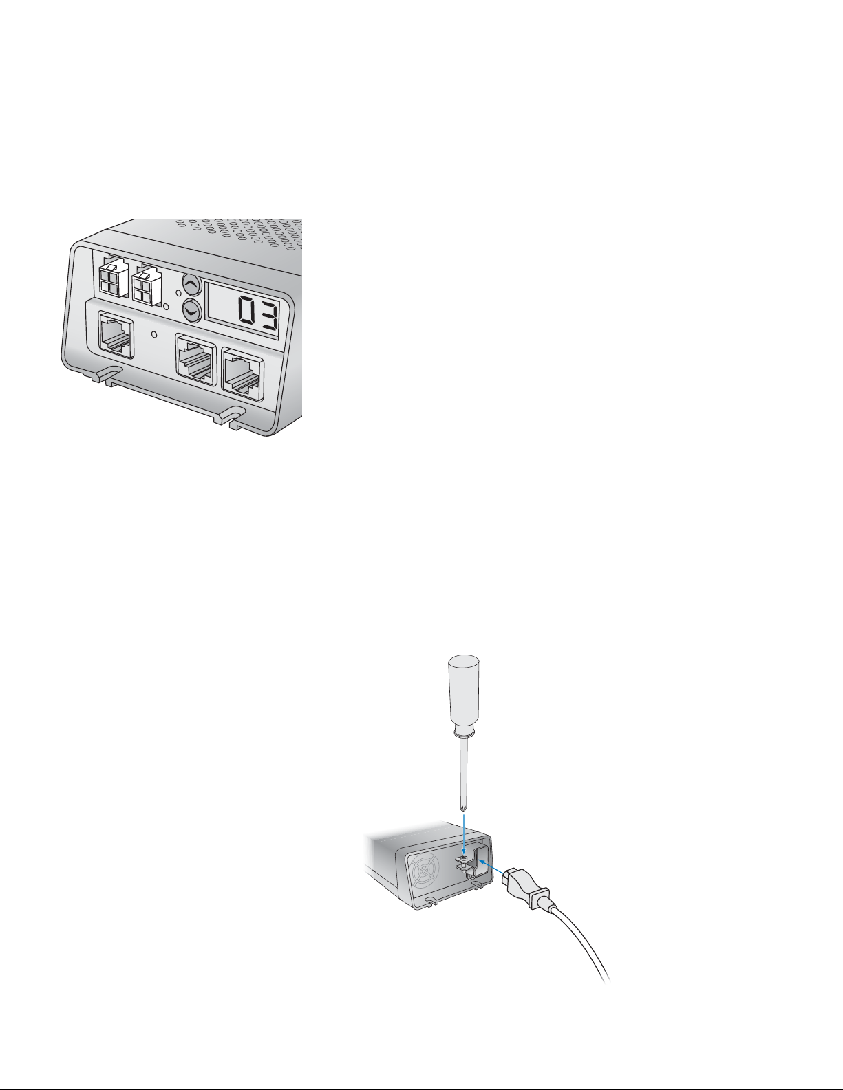
1. Connect the IEC power cable to the inlet on the back of the sPDS-60ca. Make
sure that you push the connector firmly past the locking clamp so that it meets
the bottom of the power inlet.
2. To secure the cord, tighten the locking clamp around the
screwdriver.
inlet with a Phillips
sPDS-60ca Product Guide 7
Page 8
Addressing and Controlling Fixtures
Make sure the power is ON before addressing fixtures.
Addressing methods differ depending on your environment (DMX or Ethernet).
In DMX networks, sPDS-60ca devices use DMX addresses to communicate with
connected fixture nodes. For color-changing fixtures, each node receives three
sequential DMX addresses, one for the red channel, one for the green channel, and
one for the blue channel. (eW Flex SLX nodes also receive three sequential DMX
addresses, although only the red and green channels are used.) When using a sPDS60ca device in a DMX network, fixtures are not directly programmed with DMX
addresses. Instead, you use the device’s on-board menu to discover connected nodes
and program a base light number. Discovered nodes are automatically addressed in
reference to the base light number.
A light number corresponds to three sequential DMX addresses. Since a DMX
universe consists of 512 DMX addresses, there are 170 light numbers per universe
(170 x 3 = 510, with two DMX addresses left over). Light number 1 corresponds to
DMX addresses 1, 2, and, 3; light number 2 corresponds to DMX addresses 4, 5, and
6; light number 3 corresponds to DMX addresses 7, 8, and 9; and so on.
Ethernet is the preferred environment for installations requiring large numbers
of individually controllable nodes, such as video displays and dynamic light shows
with intricate effects. In Ethernet networks, each sPDS-60ca device comes preprogrammed with a unique IP address, so it effectively functions as its own universe.
You can discover all sPDS- 60ca devices in an installation using QuickPlay Pro, which
automatically determines how many fixtures are connected to each output port and
addresses them. Light System Manager and Video System Manager Pro, Ethernet
lighting controllers from Philips Color Kinetics, also automatically discover and
address all connected fixtures.
For complete details on addressing, and on using QuickPlay Pro, refer to the
Addressing and Confi guration Guide, available at www.colorkinetics.com/support/
addressing/
E A node is an individual controllable fi xture,
or segment of a fi xture. Fixtures have one or
more nodes, depending on the fi xture type.
E You can also program base light numbers
using QuickPlay Pro addressing and confi guration
software. You can download QuickPlay Pro from
www.colorkinetics.com/support/addressing/
Light numbers and corresponding
start DMX addresses
Light Number
Start DMX Address
1 2 3 4 5 6 7 8 9 10 ...
1 4 7 10 13 16 19 22 25 28 ...
Using the On-Board Menu
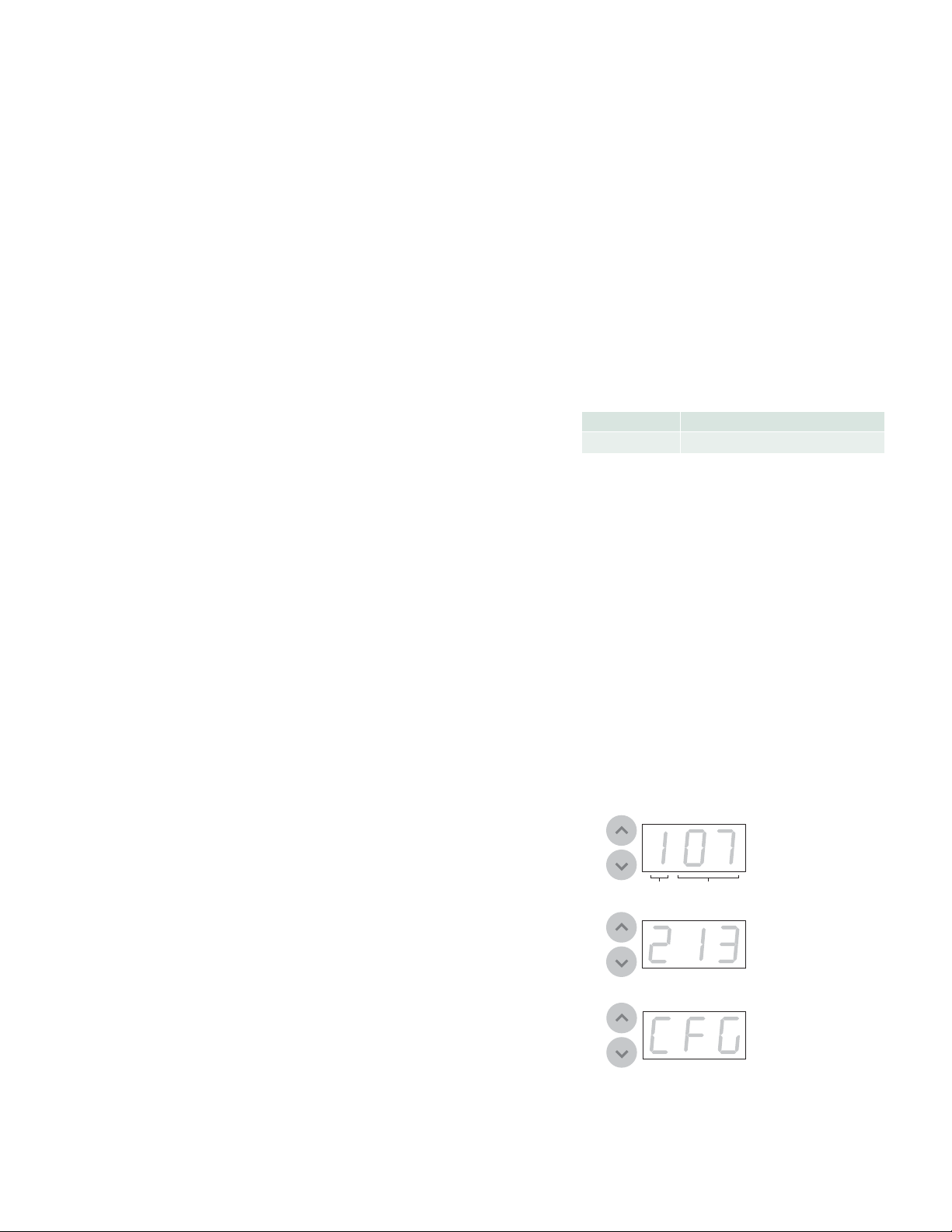
The sPDS -60ca has two buttons and a three-digit display that allow you to discover
and address connected nodes in a DMX network. (When connected to an Ethernet
network, the on-board menu is disabled.)
Discovering Nodes
When you connect fixtures or Flex strands to an sPDS -60ca, you must discover all
connected nodes. Discovery makes the sPDS-60ca aware of its nodes so that it can
assign addresses and send control data correctly.
► To discover all connected nodes:
1. Press the menu’s Up and Down buttons simultaneously. The connected nodes fl ash.
• The display shows the number of connected nodes in two consecutive
3-digit messages, fl ashing once for each port. The fi rst digit of each message
shows the port number, and the next two digits show the number of nodes
connected to the port. For example, if seven nodes are connected to port 1
and 13 nodes are connected to port 2, the display fl ashes 107, then 213.
• If no fi xtures are connected, the display fl ashes 100, then 200.
Once the node counts have been displayed, the display shows CFG (for
confi guration mode).
2. Press the Up and Down buttons simultaneously to leave confi guration mode.
sPDS-60ca Product Guide8
OUTPUT NUMBER OF NODES
EXAMPLE: 13 NODES ON OUTPUT 2
CONFIGURATION MODE
Page 9
E Make sure that the base light number
allows enough DMX addresses for all
connected nodes, or the installation will not
function properly. For example, 50 connected
RGB nodes require 50 light numbers when
each node is controlled individually. Therefore,
the base light number should be 121 or lower.
Setting a Base Light Number
Setting the base light number assigns a reference light number to the sPDS-60ca
device. Connected nodes are automatically assigned light numbers consecutvely,
beginning with the base light number. Nodes connected to port 1 are addressed first.
sPDS-60ca devices are factory-addressed with base light number 1.
In DMX networks with multiple sPDS-60ca devices, some care must be taken when
you want each each node in your network to receive a unique light number. For
instance, your lighting network may have three sPDS-60ca devices, each with 25
connected iColor Cove EC fixtures. To ensure that each node receives a unique light
address, assign base light number 1 to the first sPDS-60ca, base light number 26 to
the next device, and base light number 51 to the third.
► To set the base light number:
• Press the menu’s Up or Down button until you arrive at the desired base light
number. (Press and hold either button to scroll rapidly through the numbers.)
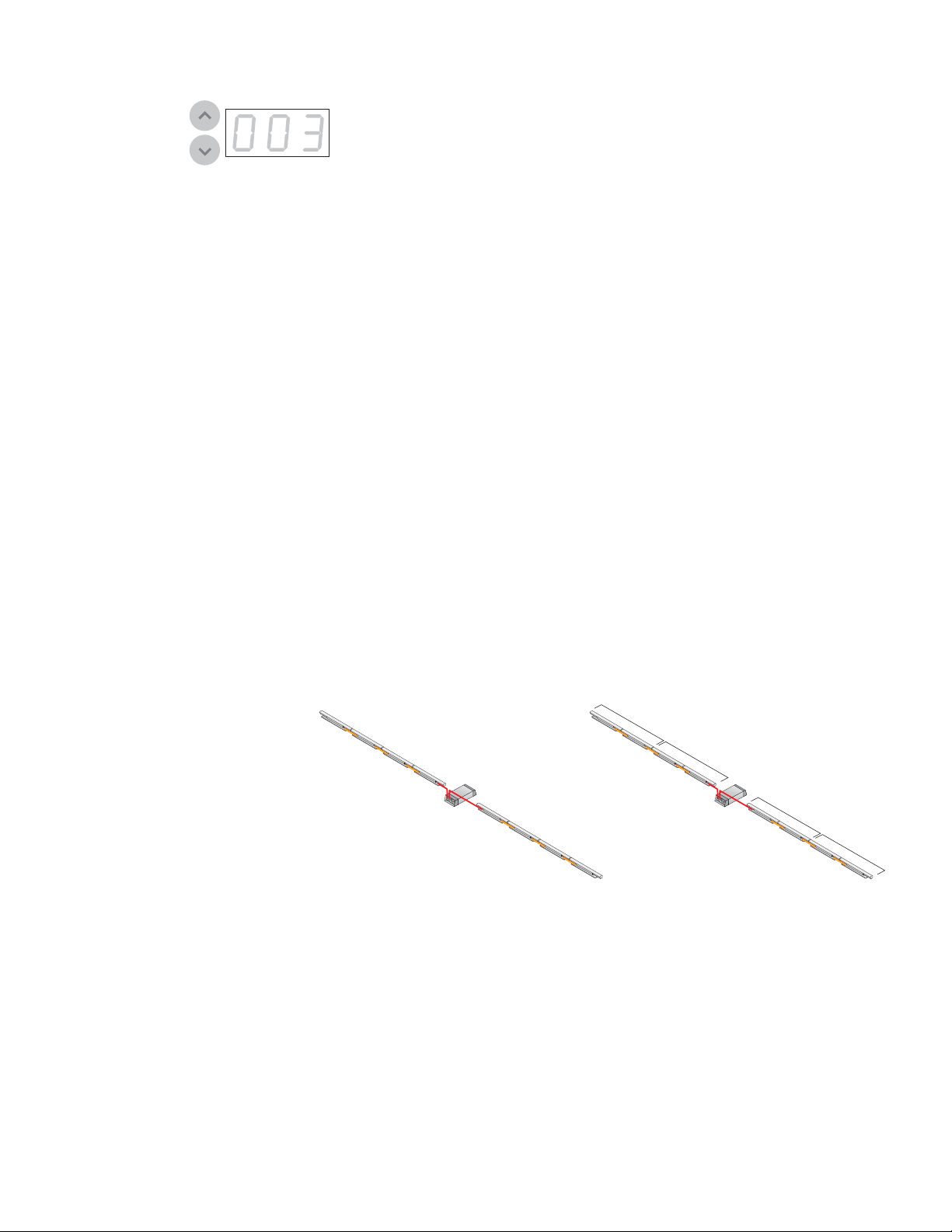
Grouping Nodes
You can group consecutive nodes together so that they operate in unison. All nodes
in a group receive the same light number, and therefore the same set of DMX
addresses. Grouping multiple nodes together decreases the total number of unique
addresses that your installation requires, and can allow you to achieve desired effects.
Understanding Group Settings
By default, sPDS-60ca has a group setting of +01, which means that each group
contains one node. With a group setting of +01, each node receives a unique light
number and is controlled individually. A group setting of +02 means that each
group contains two nodes. With a group setting of +02, each pair of consecutive
nodes receives the same light number. A group setting of +03 means that each
group contains three consecutive nodes, and so on. The maximum group size is 20
nodes, but you can set a group setting of ALL to assign the same light number to all
connected nodes (all nodes work in unison).
E Group numbers that divide evenly into
the total number of nodes in a run ensure
consistency of presentation. A consistent group
size can be important for the proper display
of video and other dynamic light show content.
Group sizes that do not divide evenly into the
total number of nodes leave an inconsistently
sized group at the end of a run. For example,
assigning a group number of 7 to a run of
17 nodes creates two groups of seven nodes
each and one smaller group of three nodes
(7 + 7 + 3 = 17).
4
3
2
iColor Cove QLX
1
Group setting is +01
(one node per group)
For Ethernet-based video displays in which each fixture node functions as a pixel, you
can increase the group size to increase the apparent size of each node. For example,
a rectilinear video display with 10 nodes on a side contains 100 total nodes. By
default, each node is assigned a unique light number can be controlled individually. If
you change the group number setting to +04, each set of four consecutive nodes is
assigned the same light number, proportionally increasing the size of each pixel in the
video display.
sPDS-60ca 24V
2
1
iColor Cove QLX
5
6
7
Group setting is +02
(two nodes per group)
8
sPDS-60ca 24V
3
4
sPDS-60ca Product Guide 9
Page 10
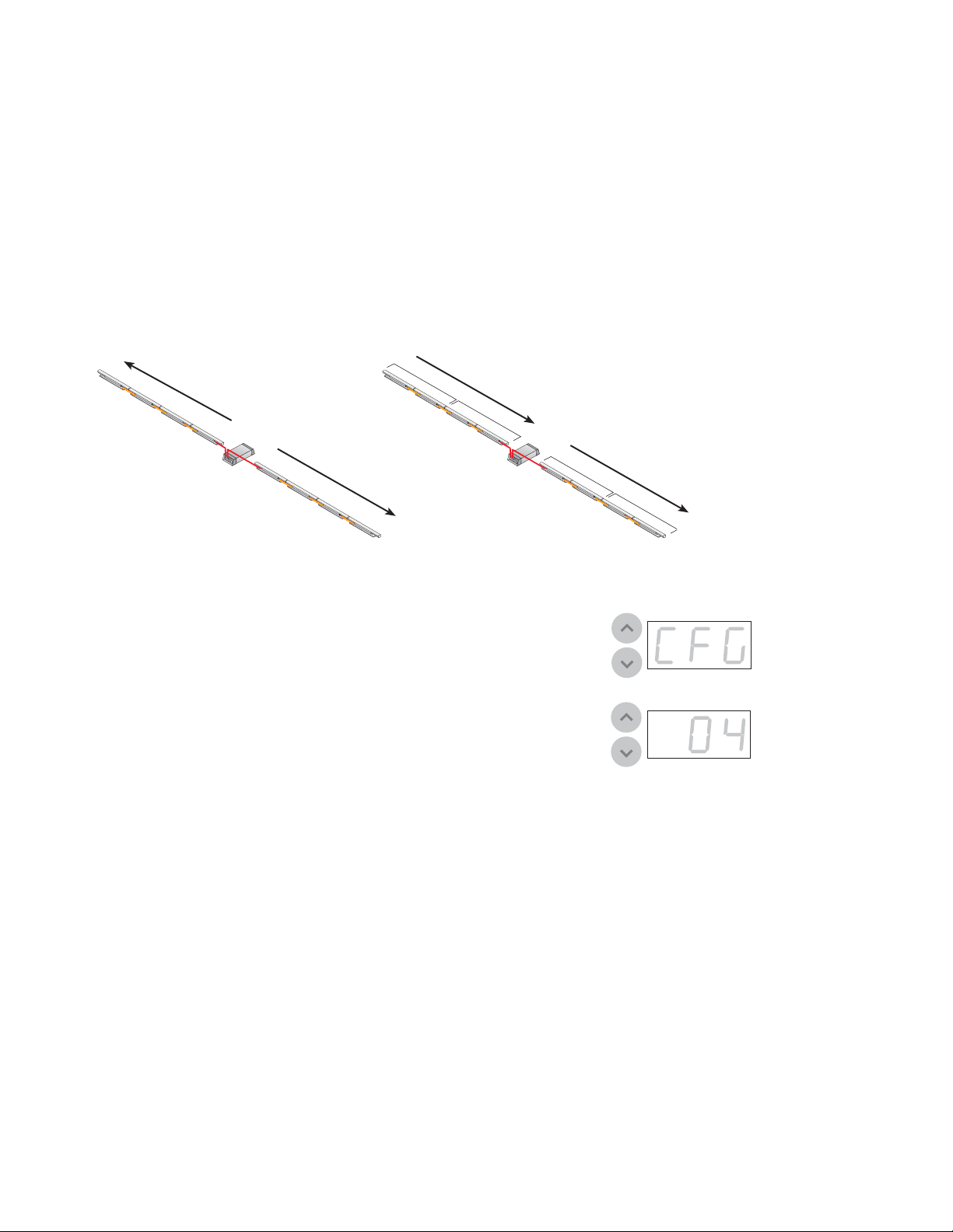
Assigning Negative Group Settings
Group settings can be positive or negative. When positive (the default), the
sequence of assigned light numbers begins at port 1, continues to the end of the
series of nodes connected to port 1, picks up at port 2, and continues to the
end of the series of nodes on port 2.
Assigning a negative group setting changes the direction in which consecutive
nodes are addressed. This can be useful if you want dynamic effects to progress
in one apparent direction, or to simplify control layouts by having node
addresses increment in a way that follows their physical layout.
When you assign a negative group setting, the sequence of assigned light
numbers begins at the end of the series of nodes connected to port 1, continues
to the node nearest to port 1, picks up at port 2, and continues to the end of
the series of nodes connected to port 2.
4
3
2
iColor Cove QLX
1
Group setting is +01
sPDS-60ca 24V
5
6
7
8
1
2
iColor Cove QLX
Group setting is -02
(direction of port 1
addresses is reversed)
► To change the group setting:
1. Press the menu’s Up and Down buttons simultaneously. The display shows
the number of lights on each port (as described in “Discovering Nodes”
above), then reads CFG (for confi guration mode).
2. Press the Up or Down arrow until you reach the desired group setting.
(ALL assigns the same light number to all connected nodes.)
3. Press the Up and Down buttons simultaneously to save the new group
setting and leave confi guration mode.
sPDS-60ca 24V
3
4
CONFIGURATION MODE
sPDS-60ca Product Guide10
Page 11

sPDS-60ca Product Guide 11
Page 12

Philips Color Kinetics
3 Burlington Woods Drive
Burlington, Massachusetts 01803 USA
Tel 888.385.5742
Tel 617.423.9999
Fax 617.423.9998
www.philipscolorkinetics.com
Copyright © 2011 Philips Solid-State Lighting Solutions, Inc. All rights reserved.
Chromacore, Chromasic, CK, the CK logo, Color Kinetics, the Color Kinetics logo, ColorBlast,
ColorBlaze, ColorBurst, eW Fuse, ColorGraze, ColorPlay, ColorReach, iW Reach, eW Reach,
DIMand, EssentialWhite, eW, iColor, iColor Cove, IntelliWhite, iW, iPlayer, Optibin, and Powercore
are either registered trademarks or trademar ks of Philips Solid-State Lighting Solutions, Inc. in
the United States and / or other countries. All other brand or product names are trademarks
or registered trademarks of their respective owners. Due to continuous improvements and
innovations, specifications may change without notice.
Cover Photo: Peeps & Company, by Mark
DAS-000065-00 R00 06-11
 Loading...