

Page 1

A Publication of
NEC PHILIPS Unified Solutions Nederland B.V.
HILVERSUM, THE NETHERLANDS
Order No : 3522 009 11319
Date : September 2007
Great care has been taken to ensure that the information
contained in this handbook is accurate and complete.
Should any errors or omissions be discovered or should any users
wish to make suggestions for improving this handbook, they are
invited to send the relevant details to:
NEC PHILIPS Unified Solutions Nederland B.V.
P.O. BOX 32
1200 JD HILVERSUM
THE NETHERLANDS
© NEC PHILIPS Unified Solutions Nederland B.V. 2007.
All rights are reserved. Reproduction in whole or in part is
prohibited without the written consent of the copyright owner. All
brand names and product names in this document are trademarks
or registered trademarks of their respective companies.
Page 2

Page 3

i
PREFACE
This manual is valid for the SOPHO 2000 IPS telephone system.
In this manual the term NEAX 2000 IPS or NEAX PBX telephone system represents the
SOPHO 2000 IPS system.
This book might refer to products not included in the SOPHO portfolio.
Certain items in this manual do not apply to the European market.
In case of doubt, please contact your supplier.
Page 4

ii
LIST OF TERMS
Abbr. NEC Description
NEC
Abbr. PBC Description / Remarks
PBC
(Trunk) Route Restriction Class TRFC Traffic Class
AIMWorX SMDR & CTI based management platform
Authorization Code PID code
Background music (feature) When phone is idle, user can have
background music on speaker
Boss/Secretary dialing Executive/Secretary
Broker's call Shuttle : alternate between 2 parties
occupying one line
Busy in/busy out - ACD Group - Absent/Present switching
Class of Service Facility Class Mark (sometimes traffic class)
Coin lines
Consecutive Speed Dialing Common number can be speed dial,
individual choice dialed manually
Consultation hold Enquiry
Development table Analysis tree : table within numbering plan
Dial conversion Conversion from pulse to DTMF
Dynamic Dial Pad Pressing numeric keys grabs a line as well.
Executive calling VIP status assigned to a station.
Ground Start Earth calling : analog trunk protocol
Hearing Aid Compatibility Voice volume control on terminals
Home side trunk User side
trunk
For ISDN trunks
Legacy TDM based equipment (non IP)
Location number Division based on capabilities or priorities in
the IP system
Loop Start Subscriber signalling e.g. an ATU-SS
Mate side trunk Network
side trunk
For ISDN trunks
MATWorX Operational Maintenance interface tool
Multi line terminal SOPHO Set / ErgoLine : digital terminal with
soft key assignment possible
Multiple Call Forwarding Multi hop (maximum 5 hops allowed)
My Line Users own station number.
Nailed down connection (data) Fixed connection between two data
adapters.
Night Connection - fixed PLE Permanent Line Extension
Night connection - fixed Permanent Line Extension
Night Connection - flexible CF on night extension
Office Code CLID Cluster Identity used for Open Numbering
Plans
One touch key Dterm keys, work (and programmed) like
speed dial function
OpenWorX CTI Application platform
Operator PSTN operator / provider
Party lines
Peer to peer Peer to peer : one to one relation on
functional level
Pilot number Group number
Preset dialing En-block dialing : prepa re number and send
it in one go (versus overlap dialing)
Prime Line Seized line (trunk line or extension) when
going off-hook (or speaker)
Restriction Class TRFC Traffic Class
Route Advance Alternative routing when trunk(s) busy
Route Pattern Tree : part of the number analysis table
Save and Repeat LNR Last Number Redial
Secondary appearance park position / sub line
Page 5

iii
Abbr. NEC Description
NEC
Abbr. PBC Description / Remarks
PBC
Single line terminal Analog Phone
Software Line Appearance Virtual Extension
Split Call Forwarding Separate CF for internal and external calls.
Stack Dial LNNR Last Number/Number Repetition
Outgoing calling list (5 entries)
Stack Dial Redial List : maximum 5 numbers
Station Extension /
DNR
Station Class FCM Facility Class Mark
Sub Line Lines on the stations, other then the prime
line
Tenant Analysis group : multi company on one PBX
Trunk Route Route
Voice Call
Whisper page Announcement without 3rd party hearing it.
AC Account Code (Client Billing Code) PID Password integrated dialing
ACF Authorization Code Facility OAI related.
ADF OAI related.
ALM DSPP (External) Alarm Display Panel
ANI Automatic Number Identification Caller subscriber number coming in with MF
signaling on T1 trunks
ANS Answer
AOC Advice of charge
AP Application Card
AP Analog Port
ATND Attendant
AttCon Attendant console Operator console
BATTM Battery Module
BGM Back Ground Music service
BHCA Busy Hour Call Attempts
BK Black
BSY Busy
BT Busy Tone
CAMA Centralized Message Accounting A standard related to 911 service
CAS Centralized Attendant Serv ice
CAT Customer Administration terminal Dterm used as programming device for PBX
CCIS Common Channel Interoffice
Signalling
Comparable to IMP
CCSA Common Control Switching
arrangement
Customer specific leased lines/network, US
only
CCT CCIS Trunk
CF-D Call Forwarding - Destination Call Forwarding – Destination : no
preparation on originator necessary.
CFT Conference trunk
CIC Circuit Identification Code Trunk channel ID for virtual IP trunk
channels (Line number)
CID Call ID Display
CIR Caller ID Re c eiver
CIS Call Information System
CM Command See Commands Manual
CNP Closed Numbering Plan
CO Central Office
COT Central Office Trunk
CPN Calling Party Number ISDN calling party number
CPN Calling Party Number
CPU Central Processing Unit
CRD Call Redirect
CS Cell Station
CSU
DAT Digital Announcement Trunk
Page 6

iv
Abbr. NEC Description
NEC
Abbr. PBC Description / Remarks
PBC
DBM Commands Manual - AP00 card
DCH D-Channel Handler
DD key Do not Disturb Key
DDD Direct Distance Dialing
DDI Direct Digital interface T1/E1 interface to public network
DDOVR Do not Disturb Override
DeskCon Desk Console SV SuperVisor / Operator Console
DID calls Direct Inward Dialing calls DDI Direct dialing in : not for FX and WATS
trunk (USA only)
DISA Direct Inward System Access Remote access to system
DIT DID trunk / Direct Inward Termination PLE Permanent Line Extension(s) : for limited
direct inward dialing: 1/more trunk(s) related
to 1 station
DLC Digital Line Circuit For Dterm, Attendant and Desk Console.
DM Distributed Module
DMS Distributed Module Small
DNIS Dialed number Identification Service
DOD Direct Outward Dialing DDO Direct Dialing Out : setting up external calls
without attendant assistance
DP (Rotary) Dial Pulse Pulse dialing
DPC Data Port Controller
DPC Destination Point Code Kind of Cluster ID; for terminating office
DRS Device Registration Server Compare with Gatekeeper function:
registering endpoints
DS Differential Services (DiffServ)
DSS/BLF Direct Station Select / Busy Lamp
Field
DSW Device Server WorX For Dterm assistant software
DT Dial Tone
DTE Data Terminal Equipment
Dterm Digital (or IP) terminal Dterm Desktop Telephone (analog or digital)
DTG Digital Tone Generator
DTI Digital Trunk Interface
FAC Forced Account Code
FCC Federal Communications
Commission
American regulation office
FD Floppy Disk
FDA Forwarded - All calls
FDB Forwarded - Busy
FDN Forwarded - No an swer
FG Frame Ground
FGD Feature Group D format Signalling format for ANI.
FLF Free Location Facility OIA related, Desksharing look-a-like.
NOT available for IPS 2000
FP Firmware Processor Compare with PMC
FX Foreign Exchange Specific part of PSTN; US only
HDT Hold Tone
HWT howler tone Alarm tone
ICH ISDN channel handler
ICI Incoming Call Identification
ICM Intercom
IEC International Electro-technical
Commission
ILC ISDN line card
IP Internet Protocol IP Internet Protocol
IPM Indications per minute For flashing lamps / LEDs
IPS Internet Protocol Server
IPT IP trunk
IPX Internet Protocol eXchange
IVS Integrated Voice Server
Page 7

v
Abbr. NEC Description
NEC
Abbr. PBC Description / Remarks
PBC
KF Key Feauture (registration) Key systems are operating directly on
outside lines.
KTF Key Transfer Facility OAI related.
LAN Local Area Network LAN Local Area Network
LCR Least Cost Routing LCCR Least cost call routing : number analysis
development manner
LDN Listed Directory Number
LDT Loop Dial trunk
LEN Line Equipment Number EHWA Equipment hardware Address : PIM nbr (0 ~
7)+ Port nbr (00 ~ 63) LEN = (000 ~ 763)
LT Line/Trunk
MAT Maintenance Administration Terminal OMM Operation Maintenance module : PC
needed in terminals mode
MB Make Busy SETOUT Set to Out Of Service : Out of Service / Not
installed situation for reset or maintenance
MCI Message Center Interface Interface for Voice Mail system
MEM Main Memory
MFG
MFR MF receiver / MFC receiver/sender
MIB management Information Base
MIC Microphone Microphone or its key
MIS management Information System
MJ Major (alarm)
MLDT Melody Trunk
MN Minor (alarm)
MOC OM terminal window, part of MATWorX
MP Main Processor Compare with CPU
MRF Mode Reset Facility OAI related.
MSF Mode Set Feature OAI related.
MSG Message
NEAX NEC PBX SOPHO
NS Network Station
NTF Number Transfer Facility OAI related.
NTS Night Transfer Station Night Extension
OAI Open Application Interface CTI interface
ODT OD Trunk 2/4 wire E&M
ODT Outband Dialing Trunk
ONP Open Numbering Plan
OPC Origional Point Code Kind of Cluster ID; for originating office
OPR Operator Attendant
PAD (IP) Packet Assembler /
Disassembler
Used for TDM / IP translation
PBR Push Button Receiver DTMF receiver
PBSND Push Button Sender DTMF sender
PC Point Code
PCK Pickup
PFT Power Failure Transfer
PIM Port Interface Module Shelf : comparable with CSM and PM
shelves
PLO Phase Locked Oscillator
PMS Property Management System PMS Property Management System (in hotel
environments)
PN Part Number For example PN-8 DLCC board
PNA Phone line Network Alliance
PPS Pulses per second Used in pulse dialing
PROTIMS Proprietary protocol, used for building CCIS
PRT ISDN primary rate interface trunk
PS Personal Station
PS Portable Station NEC wireless system
QoS Quality of Service
Page 8

vi
Abbr. NEC Description
NEC
Abbr. PBC Description / Remarks
PBC
RAS Registration Admission Status Registration Admission Status
RBT Ringback Tone
RC Room Cutoff
REN Ring Equivalence Number
RLS Release
ROT Reorder Tone
RPIM Remote PIM
RSC Route restriction Class
RST Restricted
RTP Real Time Protocol
SCF Switch Control Facility OAI related.
SDT Special Dial Tone
SLT Single Line Telephone Analog telephone
SMDR Station Message Detail Recording FDCR Full Detailed Call Recording
SMFN Status Monitor Facility (Notification) OAI related.
SMFR Status Monitor Facility (Request)
SOC System on chip
SP Soft Phone
SPID Service Profile ID (ISDN) BSP-ID Basic Service Profile ID (ISDN)
SPN Special Part Number
SSFM Service Set facility Monitor OAI related.
SSFR Service Set Facility Request OAI related.
SST Service Set Tone
STA Station
STN Station
TAH Trunk Appearance Hold
TAS Trunk Answer Any Station Pickup incoming calls in night mode
TCF Terminal Control Facility OAI related.
TCM (Deluxe) Travelling Class Mark
TDM Time division multiplexing
TDS Time division switching
TDSW Time Division Switch
TIC (Individual) Trunk identification Code Line numbers of trunk lines
TMF Terminal Multi-information transfer
Facility
OAI related.
TMSF (Terminal) Mode Set Facility OAI related.
TNT Tone/Music source interface
TRF Transfer
TSW Time Switched
UAP User Application Processor
UCD Uniform Call Distribution Basic ACD. Distribution of calls based on
longest idle.
UNP Uniform Numbering Plan (Network) numbering plan
USOC User Service Order Code Other word for REN
VC Voice Compression
VCT Voice CODEC circuit card
VDSL Very high data rate Digital Subscriber
Line
VM Voice Mail
VOIP Voice over IP VOIP Voice over IP
WAN Wide Area Network WAN Wide Area Network
WATS Wide Area Telephone Service Specific part of PSTN, US only
WCS Wireless Communication System "Analog DECT"
WH White
WU Wake up
ZT Zone Transceiver For Wireless system
Page 9

vii
Dterm icon Meaning
Hold
Transfer
Speaker
Answer
Redial
Conf(erence)
Recall
Feature
MIC
Message
Directory
- / +
Help
Exit
Page 10

viii
Page 11

NEAX 2000 IPS
Feature Programming Manual
TABLE OF CONTENTS
– i – NWA-008845-001 Rev.5.0
32toc001.fm
INTRODUCTION .................................................................................................................. 1
PURPOSE .................................................................................................................... 1
OUTLINE OF THIS MANUAL ...................................................................................... 1
TERMS IN THIS MANUAL ........................................................................................... 2
PBX System Designation ................................................................................................... 2
Terminal Name .................................................................................................................... 2
REFERENCE MANUAL ............................................................................................... 3
HOW TO READ THIS MANUAL .................................................................................. 5
AVAILABLE VALUE OF FP/AP NUMBER .................................................................. 7
LINE EQUIPMENT NUMBER (LEN) ............................................................................ 10
CONDITIONS ON CARD/TERMINAL NUMBER ASSIGNMENT BY CM14 ............... 11
PB (DTMF) RECEIVER NUMBER ............................................................................... 14
PRECAUTIONS ........................................................................................................... 16
System Data Backup .......................................................................................................... 16
Office Data Conversion ...................................................................................................... 17
CHAPTER 1 BUSINESS FEATURES ................................................................................ 19
ACCOUNT CODE ........................................................................................................ 21
ADD-ON MODULE ....................................................................................................... 22
ALPHANUMERIC DISPLAY ........................................................................................ 25
ANALOG PORT ADAPTER ......................................................................................... 29
ANNOUNCEMENT SERVICE ...................................................................................... 32
ANSWER KEY ............................................................................................................. 43
ATTENDANT ASSISTED CALLING ............................................................................ 44
ATTENDANT CAMP-ON ............................................................................................. 45
ATTENDANT CONSOLE ............................................................................................. 47
SN716 DESKCON ................................................................................................................ 47
ATTENDANT CALLED/CALLING NAME DISPLAY ........................................................... 51
ATTENDANT CALL SELECTION ........................................................................................ 55
ATTENDANT DO NOT DISTURB SETUP AND CANCEL .................................................. 56
ATTENDANT INTERPOSITION CALLING/TRANSFER ..................................................... 57
ATTENDANT LISTED DIRECTORY NUMBER ................................................................... 58
ATTENDANT LOOP RELEASE ........................................................................................... 61
ATTENDANT PROGRAMMING ........................................................................................... 62
CALL QUEUING .................................................................................................................. 63
CALL SPLITTING ................................................................................................................ 64
CALL WAITING DISPLAY ................................................................................................... 65
COMMON ROUTE INDIAL .................................................................................................. 66
Page 12

– ii – NWA-008845-001 Rev.5.0
32toc001.fm
TABLE OF CONTENTS
DIALED NUMBER IDENTIFICATION SERVICE (DNIS) ..................................................... 69
INCOMING CALL IDENTIFICATION ................................................................................... 71
INDIVIDUAL TRUNK ACCESS ............................................................................................ 72
MULTI-FUNCTION KEY ....................................................................................................... 73
MULTIPLE CONSOLE OPERATION ................................................................................... 74
PUSHBUTTON CALLING-ATTENDANT ONLY .................................................................. 75
SERIAL CALL ...................................................................................................................... 76
TRUNK GROUP BUSY DISPLAY ....................................................................................... 77
UNSUPERVISED TRUNK-TO-TRUNK TRANSFER BY ATTENDANT .............................. 78
ATTENDANT DELAY ANNOUNCEMENT ................................................................... 79
ATTENDANT OVERFLOW .......................................................................................... 81
ATTENDANT OVERRIDE ............................................................................................ 84
AUTHORIZATION CODE ............................................................................................ 86
AUTOMATED ATTENDANT ........................................................................................ 89
AUTOMATIC CALL DISTRIBUTION (ACD) ................................................................ 95
BUSY IN/BUSY OUT-ACD ................................................................................................... 98
CALL WAITING INDICATION-ACD ..................................................................................... 99
DELAY ANNOUNCEMENT-ACD ......................................................................................... 102
HUNT PAST NO ANSWER-ACD ......................................................................................... 106
IMMEDIATE OVERFLOW-ACD ........................................................................................... 106
PRIORITY QUEUING-ACD .................................................................................................. 107
QUEUE SIZE CONTROL-ACD ............................................................................................ 108
SILENT MONITOR-ACD ...................................................................................................... 109
AUTOMATIC CALL DISTRIBUTION (ACD) WITH
MANAGEMENT INFORMATION SYSTEM (MIS) ........................................................ 112
AUTOMATIC CAMP-ON .............................................................................................. 113
AUTOMATIC CHANGE TO DAYLIGHT SAVING TIME .............................................. 114
AUTOMATIC HOLD ..................................................................................................... 119
AUTOMATIC NUMBER IDENTIFICATION (ANI) ........................................................ 120
AUTOMATIC RECALL ................................................................................................ 127
BACKGROUND MUSIC ............................................................................................... 128
BOSS/SECRETARY CALLING ................................................................................... 130
BROKER’S CALL ........................................................................................................ 133
CALL BACK ................................................................................................................. 134
CALL FORWARDING .................................................................................................. 136
ATTENDANT CALL FORWARDING SET-UP AND CANCEL ............................................ 137
CALL FORWARDING-ALL CALLS ..................................................................................... 138
CALL FORWARDING-BUSY LINE ...................................................................................... 140
CALL FORWARDING-NO ANSWER .................................................................................. 142
CALL FORWARDING-DESTINATION ................................................................................ 147
CALL FORWARDING-OVERRIDE ...................................................................................... 148
MULTIPLE CALL FORWARDING-ALL CALLS .................................................................. 149
NOVEMBER/15/2006
Page 13

– iii – NWA-008845-001 Rev.5.0
32toc001.fm
TABLE OF CONTENTS
MULTIPLE CALL FORWARDING-BUSY LINE ................................................................... 149
MULTIPLE CALL FORWARDING-NO ANSWER ............................................................... 149
SPLIT CALL FORWARDING-ALL CALLS .......................................................................... 150
SPLIT CALL FORWARDING-BUSY LINE .......................................................................... 154
SPLIT CALL FORWARDING-NO ANSWER ....................................................................... 158
GROUP DIVERSION ............................................................................................................ 165
CALL PARK ................................................................................................................. 166
CALL PARK-SYSTEM ......................................................................................................... 166
CALL PARK-TENANT ......................................................................................................... 168
CALL PICKUP ............................................................................................................. 169
CALL PICKUP-DIRECT ....................................................................................................... 169
CALL PICKUP-GROUP ....................................................................................................... 170
CALL PICKUP-DESIGNATED GROUP ............................................................................... 172
CALL REDIRECT ......................................................................................................... 173
CALL TRANSFER ....................................................................................................... 174
CALL TRANSFER-ALL CALLS .......................................................................................... 174
CALL TRANSFER-ATTENDANT ........................................................................................ 175
CALLER ID CLASS ..................................................................................................... 176
CALLER ID DISPLAY .................................................................................................. 186
CALLER ID-STATION ................................................................................................. 190
CALLER ID-STATION (ETSI-FSK) .............................................................................. 193
CAMP-ON .................................................................................................................... 195
CENTREX COMPATIBILITY ....................................................................................... 198
CID CALL BACK ......................................................................................................... 199
CID CALL ROUTING ................................................................................................... 202
CLASS OF SERVICE ................................................................................................... 211
CODE RESTRICTION .................................................................................................. 214
CONFERENCE (THREE/FOUR PARTY) ..................................................................... 219
CONFERENCE (SIX/TEN PARTY) .............................................................................. 221
CONFERENCE (EIGHT PARTY) ................................................................................. 223
CONFERENCE (32-PARTY) ........................................................................................ 228
GROUP CALL ......................................................................................................................233
MEET-ME CONFERENCE ................................................................................................... 238
CONSECUTIVE SPEED DIALING ............................................................................... 240
CONSULTATION HOLD .............................................................................................. 251
CUSTOMER ADMINISTRATION TERMINAL (CAT) ................................................... 252
DATA LINE SECURITY ............................................................................................... 254
DELAYED HOTLINE .................................................................................................... 255
DELAYED RINGING .................................................................................................... 257
DIAGNOSTICS ............................................................................................................. 258
DIAL BY NAME ............................................................................................................ 259
DIAL CONVERSION .................................................................................................... 267
NOVEMBER/15/2006
Page 14

– iv – NWA-008845-001 Rev.5.0
32toc001.fm
TABLE OF CONTENTS
DIRECT DIGITAL INTERFACE ................................................................................... 270
SYSTEM OUTLINE .............................................................................................................. 270
DTI ........................................................................................................................................ 271
PLO ...................................................................................................................................... 272
SYSTEM CAPACITY ............................................................................................................ 273
HARDWARE REQUIRED .................................................................................................... 273
TIME SLOT ALLOCATION .................................................................................................. 274
DTI SPECIFICATIONS ......................................................................................................... 275
PROGRAMMING .................................................................................................................. 282
DIRECT INWARD DIALING (DID) ............................................................................... 297
DID CALL WAITING ............................................................................................................ 302
DID DIGIT CONVERSION .................................................................................................... 303
DID NAME DISPLAY ........................................................................................................... 309
DIRECT INWARD SYSTEM ACCESS (DISA) ............................................................. 311
CALL FORWARDING SET BY DISA .................................................................................. 315
DIRECT INWARD TERMINATION (DIT) ..................................................................... 321
DIRECT OUTWARD DIALING (DOD) ......................................................................... 322
DIRECT STATION SELECTION/BUSY LAMP FIELD (DSS/BLF) CONSOLE ........... 325
DISTINCTIVE RINGING ............................................................................................... 327
DO NOT DISTURB ....................................................................................................... 346
ENHANCED 911 .......................................................................................................... 354
EXECUTIVE CALLING ................................................................................................ 360
EXECUTIVE OVERRIDE ............................................................................................. 361
EXTERNAL PAGING WITH MEET-ME ....................................................................... 362
FAX ARRIVAL INDICATOR ........................................................................................ 381
FLEXIBLE LINE KEY ASSIGNMENT .......................................................................... 384
FLEXIBLE NUMBERING PLAN .................................................................................. 388
FLEXIBLE RINGING ASSIGNMENT ........................................................................... 390
FORCED ACCOUNT CODE ........................................................................................ 394
GROUP CALL .............................................................................................................. 397
AUTOMATIC CONFERENCE (6/10 PARTY) ...................................................................... 397
2 WAY CALLING ................................................................................................................. 399
GROUP CALL BY PILOT NUMBER DIALING ............................................................ 400
GROUP LISTENING .................................................................................................... 403
HOLD ........................................................................................................................... 404
CALL HOLD ......................................................................................................................... 404
DUAL HOLD ......................................................................................................................... 405
EXCLUSIVE HOLD .............................................................................................................. 406
HOTLINE-INSIDE/OUTSIDE ........................................................................................ 407
INDIVIDUAL ATTENDANT ACCESS .......................................................................... 411
INTERCEPT ANNOUNCEMENT ................................................................................. 412
INTERCOM .................................................................................................................. 414
Page 15

– v – NWA-008845-001 Rev.5.0
32toc001.fm
TABLE OF CONTENTS
MANUAL INTERCOM .......................................................................................................... 414
AUTOMATIC INTERCOM .................................................................................................... 416
DIAL INTERCOM ................................................................................................................. 418
INTERNAL TONE/VOICE SIGNALING ....................................................................... 420
INTERNAL ZONE PAGING WITH MEET-ME .............................................................. 422
LAST NUMBER REDIAL ............................................................................................. 424
LEAST COST ROUTING-3/6 DIGIT ............................................................................ 425
LINE LOCKOUT ........................................................................................................... 440
LINE PRESELECTION ................................................................................................ 441
MAINTENANCE ADMINISTRATION TERMINAL (MAT) ............................................ 442
FAULT MESSAGE ............................................................................................................... 444
FAULT REPORT SCHEDULING ......................................................................................... 444
PASSWORDS ...................................................................................................................... 444
PEG COUNT ........................................................................................................................ 445
REMOTE MAINTENANCE ................................................................................................... 446
REMOVE AND RESTORE SERVICE .................................................................................. 446
STATION LINE STATUS DISPLAY ..................................................................................... 446
STATION/TRUNK STATUS ................................................................................................. 446
MESSAGE CENTER INTERFACE (MCI) .................................................................... 447
SYSTEM OUTLINE .............................................................................................................. 447
HARDWARE REQUIRED .................................................................................................... 451
SYSTEM OPERATION ......................................................................................................... 452
PROGRAMMING .................................................................................................................. 461
MESSAGE REMINDER ............................................................................................... 473
MESSAGE WAITING ................................................................................................... 477
MISCELLANEOUS TRUNK ACCESS ......................................................................... 480
CCSA ACCESS .................................................................................................................... 480
CODE CALLING EQUIPMENT ACCESS ............................................................................ 481
DICTATION EQUIPMENT ACCESS .................................................................................... 483
FOREIGN EXCHANGE (FX) ACCESS ................................................................................ 484
RADIO PAGING EQUIPMENT ACCESS ............................................................................. 485
WIDE AREA TELEPHONE SERVICE (WATS) ACCESS ................................................... 491
MOBILITY ACCESS .................................................................................................... 492
MULTILINE TERMINAL ATTENDANT POSITION ...................................................... 507
MULTIPLE LANGUAGE DISPLAY ............................................................................. 515
MUSIC ON HOLD ........................................................................................................ 519
NIGHT SERVICE .......................................................................................................... 527
ATTENDANT NIGHT TRANSFER ....................................................................................... 527
CALL REROUTING .............................................................................................................. 528
DAY/NIGHT MODE CHANGE BY STATION DIALING ....................................................... 529
DAY/NIGHT MODE CHANGE BY SYSTEM CLOCK .......................................................... 531
JANUARY/20/2006
Page 16

– vi – NWA-008845-001 Rev.5.0
32toc001.fm
TABLE OF CONTENTS
NIGHT CONNECTION-FIXED .............................................................................................. 538
NIGHT CONNECTION-FLEXIBLE ....................................................................................... 538
OVERFLOW FOR TAS QUEUE .......................................................................................... 539
QUEUE LIMIT FOR TAS ...................................................................................................... 540
TRUNK ANSWER ANY STATION (TAS) ............................................................................ 543
NO CID CALL ROUTING ............................................................................................. 548
OFF-HOOK ALARM .................................................................................................... 553
OFF-PREMISES EXTENSIONS .................................................................................. 554
PAD LOCK ................................................................................................................... 555
PERIODIC TIME INDICATION TONE .......................................................................... 559
POOLED LINE ACCESS ............................................................................................. 560
PRIORITY CALL .......................................................................................................... 562
PRIVACY ...................................................................................................................... 563
PRIVATE LINES .......................................................................................................... 565
PROPRIETARY MULTILINE TERMINAL .................................................................... 566
AUTOMATIC IDLE RETURN ............................................................................................... 574
CALLING NAME AND NUMBER DISPLAY ........................................................................ 575
DYNAMIC DIAL PAD ........................................................................................................... 576
GROUP FEATURE KEY ...................................................................................................... 577
MULTIPLE LINE OPERATION ............................................................................................ 578
MUTE KEY ........................................................................................................................... 579
MY LINE NUMBER DISPLAY .............................................................................................. 580
PRESET DIALING ................................................................................................................ 581
PRIME LINE PICKUP ........................................................................................................... 582
RECALL KEY ....................................................................................................................... 583
RELAY CONTROL FUNCTION KEY ................................................................................... 584
RING FREQUENCY CONTROL .......................................................................................... 586
RINGING LINE PICKUP ....................................................................................................... 590
SOFT KEY ............................................................................................................................ 591
VOLUME CONTROL ............................................................................................................ 595
REMOTE HOLD ........................................................................................................... 596
RETURN MESSAGE SCHEDULE DISPLAY .............................................................. 598
ROUTE ADVANCE ...................................................................................................... 599
SAVE AND REPEAT ................................................................................................... 600
SECURITY ALARM ..................................................................................................... 601
SEMI-AUTOMATIC CAMP-ON .................................................................................... 602
SET RELOCATION ...................................................................................................... 604
SHORT MESSAGE SERVICE (SMS) .......................................................................... 605
SINGLE DIGIT FEATURE ACCESS CODE ................................................................ 606
SOFTWARE LINE APPEARANCE (VIRTUAL EXTENSIONS) ................................... 609
STACK DIAL ................................................................................................................ 610
STATION HUNTING .................................................................................................... 612
DECEMBER/02/2005
Page 17

– vii – NWA-008845-001 Rev.5.0
32toc001.fm
TABLE OF CONTENTS
STATION HUNTING-CIRCULAR ......................................................................................... 612
STATION HUNTING-TERMINAL ......................................................................................... 613
STATION HUNTING-SECRETARIAL .................................................................................. 614
STATION MESSAGE DETAIL RECORDING (SMDR) ................................................ 615
SYSTEM OUTLINE .............................................................................................................. 615
SYSTEM CAPACITY ............................................................................................................ 620
COMBINATION OF SMDR SERVICE .................................................................................. 621
HARDWARE REQUIRED .................................................................................................... 622
PROGRAMMING SUMMARY .............................................................................................. 623
PROGRAMMING .................................................................................................................. 624
STATION SPEED DIALING ......................................................................................... 665
STEP CALL .................................................................................................................. 674
SUPERVISORY CONTROL OF PERIPHERAL EQUIPMENT .................................... 675
SYSTEM CLOCK SETUP BY STATION DIALING ...................................................... 676
SYSTEM SPEED DIALING .......................................................................................... 677
TENANT SERVICE ...................................................................................................... 685
TIE LINES .................................................................................................................... 688
TIE LINE TANDEM SWITCHING ................................................................................. 697
TIMED FORCED RELEASE ........................................................................................ 698
TIMED QUEUE ............................................................................................................. 700
TIMED REMINDER ...................................................................................................... 701
TRUNK-DIRECT APPEARANCES .............................................................................. 709
TRUNK QUEUING-OUTGOING .................................................................................. 715
TRUNK-TO-TRUNK CONNECTION ............................................................................ 716
UNIFORM CALL DISTRIBUTION (UCD) ..................................................................... 720
BUSY IN/BUSY OUT-UCD ................................................................................................... 723
CALL WAITING INDICATION-UCD ..................................................................................... 724
DELAY ANNOUNCEMENT-UCD ......................................................................................... 727
HUNT PAST NO ANSWER-UCD ......................................................................................... 732
IMMEDIATE OVERFLOW-UCD ........................................................................................... 732
PRIORITY QUEUING-UCD .................................................................................................. 732
QUEUE SIZE CONTROL-UCD ............................................................................................ 732
SILENT MONITOR-UCD ...................................................................................................... 733
UNIFORM NUMBERING PLAN (UNP)-VOICE AND DATA ........................................ 736
VARIABLE TIMING PARAMETERS ........................................................................... 744
VOICE GUIDE .............................................................................................................. 745
VOICE MAIL INTEGRATION ....................................................................................... 748
VOICE MAIL TRANSFER ............................................................................................ 752
WHISPER PAGE .......................................................................................................... 754
CHAPTER 2 HOTEL FEATURES ...................................................................................... 755
HOTEL SYSTEM OUTLINE ......................................................................................... 756
JUNE/01/2007
Page 18

– viii – NWA-008845-001 Rev.5.0
32toc001.fm
TABLE OF CONTENTS
HOTEL SYSTEM CAPACITY ...................................................................................... 761
HOTEL SYSTEM SPECIFICATIONS .......................................................................... 762
HOTEL FEATURE LIST ............................................................................................... 764
HOTEL SYSTEM PROGRAMMING SUMMARY ......................................................... 766
HOTEL SYSTEM PROGRAMMING ............................................................................ 767
PRECAUTION ......................................................................................................................767
STATION NUMBER DATA LOADING ................................................................................. 767
DIGITS OF STATION NUMBER .......................................................................................... 767
AP INITIALIZATION (PN-AP00-B WITH AP00 PROGRAM) .............................................. 768
AP CONTROLLED STATIONS ............................................................................................ 769
AP INITIALIZATION (PN-AP00-B/PN-AP00-D WITH MRCA PROGRAM) ......................... 770
HOTEL FEATURE PROGRAMMING .................................................................................. 771
AUTOMATIC WAKE UP ...................................................................................................... 772
CHECK IN/CHECK OUT ...................................................................................................... 780
DIRECT DATA ENTRY ........................................................................................................ 786
DO NOT DISTURB-HOTEL/MOTEL .................................................................................... 788
DO NOT DISTURB-SYSTEM ............................................................................................... 794
HOTEL/MOTEL ATTENDANT CONSOLE .......................................................................... 798
HOTEL/MOTEL DID NUMBER ALLOCATION TO GUEST STATION ............................... 799
HOTEL/MOTEL FRONT DESK INSTRUMENT ................................................................... 800
HOTEL/MOTEL TOLL RESTRICTION CHANGE-GUEST STATION ................................. 807
HOUSE PHONE ................................................................................................................... 809
MAID STATUS .....................................................................................................................810
MESSAGE REGISTRATION ................................................................................................ 815
MESSAGE WAITING ........................................................................................................... 818
PROPERTY MANAGEMENT SYSTEM INTERFACE ......................................................... 821
ROOM CUTOFF ................................................................................................................... 832
ROOM STATUS ................................................................................................................... 837
SINGLE DIGIT DIALING ...................................................................................................... 838
APPENDIX A TERMINAL KEY ASSIGNMENT ................................................................. A1
D
term
85/D
term
IP Key Numbers ................................................................................... A2
D
term
75 Key Numbers ................................................................................................. A8
D
term
65 Key Numbers ................................................................................................. A11
DESKCON Key Numbers ........................................................................................... A16
DSS Console Key Numbers ....................................................................................... A17
Add-On Module Key Numbers ................................................................................... A19
APPENDIX B CHARACTER CODE TABLE ...................................................................... B1
JUNE/01/2007
Page 19

INTRODUCTION
– 1 – NWA-008845-001 Rev.5.0
32ch0001.fm
INTRODUCTION
PURPOSE
This manual explains the feature programming and hardware requirements for each business and hotel service feature in the NEAX 2000 IPS.
OUTLINE OF THIS MANUAL
This manual consists of two chapters and three appendixes. The following paragraphs summarize Chapters
1 and 2, and Appendixes A through B.
CHAPTER 1 BUSINESS FEATURES
This chapter explains the programming procedure and hardware requirements for
Business Features in this system.
CHAPTER 2 HOTEL FEATURES
This chapter explains the system outline, system capacity, system specifications,
system programming and hardware requirements for the Hotel System.
APPENDIX A TERMINAL KEY ASSIGNMENT
This appendix contains the key number layout of each D
term
, DESKCON, DSS
Console, and Add-On Module.
Refer to this appendix to assign a key function by CM90 or CM97 in Chapter 1 and
Chapter 2.
APPENDIX B CHARACTER CODE TABLE
This appendix contains the character code table to set a station name displayed on
D
term
or Attendant Console.
JULY/01/2006
PURPOSE/OUTLINE OF THIS MANUAL
Page 20

INTRODUCTION
– 2 – NWA-008845-001 Rev.5.0
32ch0001.fm
TERMS IN THIS MANUAL
PBX System Designation
PBX system is designated as “PBX” or “system” usually.
When we must draw a clear line between the PBX systems, they are designated as follows.
2000 IPS : NEAX 2000 IPS INTERNET PROTOCOL SERVER
2400 IPX: NEAX 2400 IPX Internet Protocol eXchange
IPS
DMR
: NEAX IPS
DMR
INTERNET PROTOCOL SERVER
DMR
IPS
DM
: NEAX IPSDM INTERNET PROTOCOL SERVER
DM
Terminal Na me
The following IP terminals are designated as “D
term
IP” usually, unless we need to mention the type of terminal in particular.
D
term
IP (IP Adapter Type)
D
term
IP (IP Bundled Type)
D
term
IP INASET
D
term
SP20
D
term
SP30
NOTE: D
term
75 (Series E)/D
term
85 (Series i) terminal can be used as the IP terminal by attaching the
IP Adapter (IP Enabled D
term
). This terminal provides users with all features currently avail-
able in D
term
IP.
DECEMBER/02/2005
TERMS IN THIS MANUAL
Page 21

INTRODUCTION
– 3 – NWA-008845-001 Rev.5.0
32ch0001.fm
REFERENCE MANUAL
For details of the service feature, operating procedure and the service conditions of the features which are
mentioned in this manual, refer to the Business/Hotel/Data Features and Specifications.
For details of the system description of NEAX 2000 IPS system, refer to the System Manual.
For details of the description of each command, refer to the Command Manual.
For the features which are not mentioned in this manual, refer to the individual manuals listed below.
Business/Hotel/Data Features and Specifications:
This contains the Business/Hospitality Data Features and Specifications which explains each service
feature, operating procedure, and service conditions.
System Manual:
Contains the system description, hardware installation procedure and the programming procedure for
the NEAX 2000 IPS System.
Command Manual:
Contains the Customer Administration Terminal (CAT) operation, command functions, data required
for programming the system and the Resident System Program.
AD-8 System Manual:
Contains the hardware installation procedure and the programming procedure for the NEAXMail
AD-8 Voice Mail System.
IM-16 System Manual:
Contains the hardware installation procedure and the programming procedure for the NEAXMail
IM-16 Voice Mail System.
CCIS System Manual:
Contains the system description, hardware installation procedure, programming procedure and the
operation test procedure for the CCIS System.
ISDN System Manual:
Contains the system description, hardware installation procedure, programming procedure and the
operation test procedure for the ISDN System.
Maintenance Manual:
Contains the programming procedure for maintenance service features and the recommended troubleshooting procedure.
DECEMBER/02/2005
REFERENCE MANUAL
Page 22

INTRODUCTION
– 4 – NWA-008845-001 Rev.5.0
32ch0001.fm
OAI System Manual:
Contains the system description, hardware installation procedure, programming procedure and troubleshooting procedure for Open Application Interface (OAI).
Q-SIG System Manual:
Contains the system description, hardware installation procedure, and programming procedure for
the Q-SIG System.
Remote PIM System Manual:
Contains the system description, hardware installation procedure, and troubleshooting procedure for
the TDM based Remote PIM System.
NOTE: TDM based Remote PIM System is not available from Series 3200 R6.2.
WCS System Manual:
Contains the system description, hardware installation procedure, programming procedure for the
Wireless (WCS) System.
NEAX IPSDM Hardware Installation Guide:
Contains the general information and installation procedure for the NEAX IPSDM (Internet Protocol
Server Distributed Model)/NEAX IPS
DMR
(Internet Protocol Server Distributed Model Remote)
System.
REFERENCE MANUAL
Page 23
INTRODUCTION
– 5 – NWA-008845-001 Rev.5.0
32ch0001.fm
HOW TO READ THIS MANUAL
Chapter 1 and Chapter 2 explains the feature programming for each service feature about the following
items.
PROGRAMMING
This section explains the programming procedure for each service feature.
The meanings of (1), (2) and marking are as follows.
(1) : 1st data
(2) : 2nd data
: Initial data; With the system data clear command (CM00, CM01), the data with this marking is au-
tomatically set for each command.
: A reset of the MP card is required after data setting.
Press SW1 switch on the MP card.
: A reset of the AP00 card is required after data setting.
Set the Make Busy switch to UP and then DOWN.
: A reset of the CFTC card is required after data setting.
Set the Make Busy switch to UP and then DOWN.
: A reset of the DTI card is required after data setting.
Set the Make Busy switch to UP and then DOWN.
: A reset of the CIR card is required after data setting.
Set the Make Busy switch to UP and then DOWN.
: Command with this marking can be used only under Off-Line mode of the MP card.
To set Off-Line mode,
(1) Set SW3 on the MP card to “2” or “3”.
(2) Press SW1 on the MP card.
: Command with this marking can be used only under Off-Line mode of the AP00
card.
INITIAL
AP00 INITIAL
CFT INITIAL
DTI INITIAL
CIR INITIAL
OFF LINE
AP OFF LINE
HOW TO READ THIS MANUAL
Page 24

INTRODUCTION
– 6 – NWA-008845-001 Rev.5.0
32ch0001.fm
HARDWARE REQUIRED
In this section, required hardware for each service feature is listed, except the following:
Single line telephone set and interface card (LC card)
Central Office Trunk card (COT card)
Attendant Console and interface card
For Direct Digital Interface, Message Center Interface (MCI), and Station Message Detail Recording (SMDR), the following sections explain the system for further details.
SYSTEM OUTLINE
DTI*
PLO*
SYSTEM CAPACITY
SYSTEM OPERATION**
TIME SLOT ALLOCATION*
DTI SPECIFICATIONS*
PROGRAMMING SUMMARY***
* : Direct Digital Interface only
** : MCI only
***: SMDR only
JULY/01/2006
HOW TO READ THIS MANUAL
Page 25

INTRODUCTION
– 7 – NWA-008845-001 Rev.5.0
32ch0001.fm
AVAILABLE VALUE OF FP/AP NUMBER
For the setting of LEN by CM14, the range of the FP/AP number that must be assigned to the 1st data of
CM14 is valid by the software version you use.
Assign the correct FP/AP number to each FP/AP, referring to the tables below.
[For Series 3200 R6.1 software or before]
×: Available –: Not available
[For Series 3200 R6.2 software]
×: Available –: Not available
FP/AP No.
FP/AP TYPE
00 01-03 04-15 16-19 20-31 32-59 60-63
FP card (PN-CP15) – × – × –––
MP built-in FP × ––––––
DAIA/DAID card – × – × –––
Virtual FP for D
term
IP – × – × –––
AP card – – × – × ––
Virtual AP (Virtual IPT) – – × – × ––
FP/AP No.
FP/AP TYPE
00 01-03 04-15 16-19 20-31 32-59 60-63
FP card (PN-CP15) – × – × –––
MP built-in FP × ––––––
Virtual FP for D
term
IP – ××××––
AP card – – × – × ––
Virtual AP (Virtual IPT) – – × – × ––
AVAILABLE VALUE OF FP/AP NUMBER
Page 26

INTRODUCTION
– 8 – NWA-008845-001 Rev.5.0
32ch0001.fm
[For Series 3300 software]
×/∆: Available NOTE –: Not available
NOTE: Although FP/AP number marked with “∆” is available to use, we recommend FP/AP number
marked with “×”.
FP/AP No.
FP/AP TYPE
00 01-03 04-15 16-19 20-31 32-59 60-63
FP card (PN-CP15) – × – × –––
MP built-in FP × ––––––
Virtual FP for D
term
IP – ×∆×∆∆–
AP card – – × – × ––
Virtual AP (Virtual IPT/
Virtual CSH [For PHS])
––∆ – ∆×–
Virtual FP for PS Station – ∆ ––––×
AVAILABLE VALUE OF FP/AP NUMBER
Page 27

INTRODUCTION
– 9 – NWA-008845-001 Rev.5.0
32ch0001.fm
[For Series 3400 software or later]
×/∆: Available NOTE 1 –: Not available
NOTE 1: Although FP/AP number marked with “∆” is available to use, we recommend FP/AP number
marked with “×”.
NOTE 2: We recommend the setting of the FP number (60-63), when providing 256 PS stations/WLAN
stations or less and setting of the FP number (56-63), when providing 257 PS stations/WLAN
stations or more.
NOTE 3: Virtual CSH for WLAN and Virtual FP for WLAN Station are available for Series 3500 software
or later.
FP/AP No.
FP/AP TYPE
00 01-03 04-15 16-19 20-31 32-59 60-63
FP card (PN-CP15) – × – × –––
MP built-in FP × ––––––
Virtual FP for D
term
IP – ×∆×∆∆–
AP card – – × – × ––
Virtual AP (Virtual IPT/
Virtual CSH for IP-CS
[For PHS]/Virtual CSH for
WLAN) NOTE 3
––∆ – ∆×–
Virtual FP for PS Station/
Virtual FP for WLAN
Station NOTE 3
– ∆ –––×
NOTE 2
×
AVAILABLE VALUE OF FP/AP NUMBER
Page 28

INTRODUCTION
– 10 – NWA-008845-001 Rev.5.0
32ch0001.fm
LINE EQUIPMENT NUMBER (LEN)
The system allows all the CM10 setting data to be also assigned by CM14 from Series 3200 R6.2. When
your system contains Series 3200 R6.2 or later software, we recommend you to assign station number,
trunk number and card number by CM14.
This manual explains the feature programming using CM10. For the feature programming using CM14,
follow the LEN assignment shown below.
• LEN assignment by CM14
Level 0
Level 1
Level 2
Level 3
Level 4
Level 5
Level 6
Level 7
LT card accommodation position
number in Physical PIM/
Virtual station of D
term
IP
accommodation position in Virtual
PIM
XXZZZ
XXZZZ
XXZZZ
XXZZZ
XXZZZ
XXZZZ
XXZZZ
XXZZZ
(LTXX)
XX
ZZZ: Port Number of Physical PIM/
Virtual PIM (000-127)
: FP Number (00-59)
[For Series 3300 software or later]
XX
ZZZ: Port Number of Physical PIM/
Virtual PIM (000-127)
: FP Number (00-31)
[For Series 3200 R6.2 software or before]
LINE EQUIPMENT NUMBER (LEN)
Page 29

INTRODUCTION
– 11 – NWA-008845-001 Rev.5.0
32ch0001.fm
CONDITIONS ON CARD/TERMINAL NUMBER ASSIGNMENT
BY CM14
In the Series 3200 R6.2 or later software, the card/terminal number can be assigned by CM14 same as
CM10. But, you must consider the following conditions on the card/terminal number assignment.
(1) Card Number of AMP Trunk (PN-2AMP) <C100-C163>
(a) The card number should be assigned to the FP No. 00-03 as follows.
For FP No. 00: C100-C115
For FP No. 01: C116-C131
For FP No. 02: C132-C147
For FP No. 03: C148-C163
(b) Do not assign the card number to the other FP No. than above (a).
(c) This data is not effective for a remote site of Remote PIM over IP system.
(2) DSS Console number <E100-E131>
(a) For the FP No. 00-03, the DSS Console number should be assigned as follows.
[Series 3400 R9.1 software or before]
For FP No. 00: E100-E107
For FP No. 01: E108-E115
For FP No. 02: E116-E123
For FP No. 03: E124-E131
(b) For the FP No. 00-03 of MP built-in FP/FP card of Main Site and MP built-in FP of Remote Site,
the DSS Console number (E100-E131) can be assigned without limit as shown above (a).
[Series 3500 software or later]
(c) For the other FP No. than above (a), the DSS Console number (E100-E131) can be assigned
without limit as shown above (a).
(d) This data is effective for a remote site of Remote PIM over IP system.
(e) The same number (the last two digits of the data) should not be used for both DSS Console
number (E100-E131) and Add-On Module number (EC00-EC31).
JULY/01/2006
CONDITIONS ON CARD/TERMINAL NUMBER ASSIGNMENT BY CM14
Page 30

INTRODUCTION
– 12 – NWA-008845-001 Rev.5.0
32ch0001.fm
(3) Card Number of PB receiver (PN-8RST) <E201-E215>
(a) The card number should be assigned to the FP No. 00-03 as follows.
For FP No. 00: E201-E203
For FP No. 01: E204-E207
For FP No. 02: E208-E211
For FP No. 03: E212-E215
(b) For the other FP No. than above (a), the card number (E201-E215) can be assigned to without
limit as shown above (a).
(c) The card numbers (E200, E216-E230) are used for MP built-in DTMF Receiver. For details,
refer to PB (DTMF) RECEIVER NUMBER. Page 14
(4) Card Number of External Equipment Interface (PN-DK00) <E800-E831>
(a) The card number should be assigned to the FP No. 00-03 as follows.
For FP No. 00: E800-E807
For FP No. 01: E808-E815
For FP No. 02: E816-E823
For FP No. 03: E824-E831
(b) Do not assign the card number to the other FP No. than above (a).
(c) This data is not effective for a remote site of Remote PIM over IP system.
(d) Circuit No. 3 of E831 is used for built-in External Equipment Interface of MP card by setting
CM44.
(5) Card Number of External Key Interface (PN-DK00) <E900-E963>
(a) The card number should be assigned to the FP No. 00-03 as follows.
For FP No. 00: E900-E915
For FP No. 01: E916-E931
For FP No. 02: E932-E947
For FP No. 03: E948-E963
(b) Do not assign the card number to the other FP No. than above (a).
(c) This data is not effective for a remote site of Remote PIM over IP system.
(d) Circuit No. 3 of E963 is used for built-in External Key Interface of MP card by setting CM61.
JULY/01/2006
CONDITIONS ON CARD/TERMINAL NUMBER ASSIGNMENT BY CM14
Page 31

INTRODUCTION
– 13 – NWA-008845-001 Rev.5.0
32ch0001.fm
(6) Card Number of Digital Announcement Trunk (PN-2DATA/4DATA) <EB002-EB127>
(a) The card number should be assigned to the FP No. 00-03 as follows.
For FP No. 00: EB002-EB031
For FP No. 01: EB032-EB063
For FP No. 02: EB064-EB095
For FP No. 03: EB096-EB127
(b) Do not assign the card number to the other FP No. than above (a).
(c) This data is not effective for a remote site of Remote PIM over IP system.
(d) The card numbers (EB000 and EB001) are dedicated to built-in Digital Announcement Trunk of
MP card.
(7) Add-On Module number <EC00-EC31>
(a) For the FP No. 00-03, the Add-On Module number should be assigned as follows.
For FP No. 00: EC00-EC07
For FP No. 01: EC08-EC15
For FP No. 02: EC16-EC23
For FP No. 03: EC24-EC31
(b) For the other FP No. than above (a), the Add-On Module number (EC00-EC31) can be assigned
without limit as shown above (a).
(c) This data is effective for a remote site of Remote PIM over IP system.
(d) The same number (the last two digits of the data) should not be used for both DSS Console
number (E100-E131) and Add-On Module number (EC00-EC31).
JULY/01/2006
CONDITIONS ON CARD/TERMINAL NUMBER ASSIGNMENT BY CM14
Page 32

INTRODUCTION
– 14 – NWA-008845-001 Rev.5.0
32ch0001.fm
PB (DTMF) RECEIVER NUMBER
A system with Series 3200 R6.2 software provides the MP built-in PB (DTMF) Receiver for a Remote Site
of Remote PIM over IP feature. For the Series 3200 R6.2 or later software, the DTMF Receiver card number is as follows.
• MP built-in DTMF Receiver in Main Site : E200 (This number is also used when a system is not
provided Remote PIM over IP feature.)
• 8RST card in Main Site : E201-E215 (This number is also used when a system
is not provided Remote PIM over IP feature.)
• MP built-in DTMF Receiver in Remote Site: E216-E230 (E216-E230 matches Remote Site number
01-15)
[For Series 3200 R6.2 software]
E216-E245 (E216-E245 matches Remote Site number
01-30)
[For Series 3300 software or later]
NOTE: When a system is not provided Remote PIM over IP feature or a system is a Main Site of Remote
PIM over IP feature, you can assign maximum four DTMF Receiver card numbers per FP (includes the number for MP built-in DTMF Receiver). For the Remote Site, MP built-in DTMF
Receiver can be used per Remote Site.
For CM45 setting data, DTMF Receiver number in Series 3200 R6.2 or later is as shown below.
• CM45 Y=0 (Make Busy)
(1) XX Z (DTMF Receiver No.)
XX: 00-30 (MP Built-in DTMF Receiver/8RST Card No.)
[For Series 3200 R6.2 software]
00-45 (MP Built-in DTMF Receiver/8RST Card No.)
[For Series 3300 software or later]
Z : 0-3 (Circuit No.)
(2) 0 : Make busy
1 : In service
• CM45 Y=1 (DTMF Receiver for incoming call from Tie Line/DID)
(1) XX Z (DTMF Receiver No.)
XX: 00-30 (MP Built-in DTMF Receiver/8RST Card No.)
[For Series 3200 R6.2 software]
00-45 (MP Built-in DTMF Receiver/8RST Card No.)
[For Series 3300 software or later]
Z : 0-3 (Circuit No.)
(2) 0 : Only for incoming call from Tie Line/DID
1 : For both DTMF station and Tie Line/DID
PB (DTMF) RECEIVER NUMBER
Page 33

INTRODUCTION
– 15 – NWA-008845-001 Rev.5.0
32ch0001.fm
• CM45 Y=2 (DTMF Receiver for Automated Attendant only)
(1) XX Z (DTMF Receiver No.)
XX: 00-30 (MP Built-in DTMF Receiver/8RST Card No.)
[For Series 3200 R6.2 software]
00-45 (MP Built-in DTMF Receiver/8RST Card No.)
[For Series 3300 software or later]
Z : 0-3 (Circuit No.)
(2) 0 : Only for Automated Attendant
1 : For both DTMF station and Tie Line/DID/Automated Attendant
PB (DTMF) RECEIVER NUMBER
Page 34

INTRODUCTION
– 16 – NWA-008845-001 Rev.5.0
32ch0001.fm
PRECAUTIONS
System Data Backup
CAUTION
• If you operate as follows without system data backup after system data setting or service
memory setting (registration of the features such as “Call Forwarding” and “Speed Calling
[Speed Dialing]” from a station), the data that has been set is invalid.
You must execute the system data backup before the following operations.
-Turning Off the system
-System Initialization (reset of MP card)
-Changing the MP card to Off-Line Mode
-Changing the MP card to On-Line Mode after system data setting under Off-Line Mode
• You can execute the system data backup by the following two ways.
-Executing the system data backup once a day at the time set by CM43 Y=5>00
(If no data is set, the default setting is 3:00 a.m.)
-Executing the system data backup from MAT/CAT by CMEC Y=6>0:0
• Do not reset the MP card while “SYSD” lamp on the MP card is flashing.
DECEMBER/02/2005
PRECAUTIONS
Page 35

INTRODUCTION
– 17 – NWA-008845-001 Rev.5.0
32ch0001.fm
Office Data Conversion
When upgrading the software of the system from Series 3300 or before to Series 3400 or later, the office
data conversion by CM00>90 is required. The office data that has been converted and the office data in
Series 3400 software or later are incompatible with the software of Series 3300 or before. We recommend
to execute the system data backup before the office data conversion.
NOTE: When upgrading the software in Retrofit system to Series 3400 or later, convert the office data
using “Office Data Converter” in the MATWorX CD-ROM and then execute the office data
conversion by CM00>90.
DESCRIPTION DATA
Execute the office data conversion.
[Series 3200 R6.2 software required]
(1)
(2)900: Start conversion
1: Always displayed after first data “90” is
typed NOTE 1
NOTE 1: When first data “90” is typed, second data “1” is displayed. Also while converting the
office data, “1” is displayed.
NOTE 2: There is no problem even if the office data conversion is executed repeatedly.
START
CM00
OFF LINE
END
DECEMBER/02/2005
PRECAUTIONS
Page 36

– 18 – NWA-008845-001 Rev.5.0
32ch0001.fm
THIS PAGE LEFT BLANK INTENTIONALLY.
Page 37

– 19 – NWA-008845-001 Rev.5.0
32ch1001.fm
CHAPTER 1
BUSINESS FEATURES
This chapter explains the programming procedure and hardware requirements for Business Features in this system.
Explanations are given in alphabetical order of the feature names except the
features on the next page.
CHAPTER 1 BUSINESS FEATURES
Page 38

CHAPTER 1 BUSINESS FEATURES
– 20 – NWA-008845-001 Rev.5.0
32ch1001.fm
The following features require no programming.
For the following features, refer to the NEAX 2000 IPS manuals mentioned below.
Refer to the System Manual:
Refer to the D
term
Assistant User Guide:
•D
term
Assistant
Refer to the Open Application Interface (OAI) System Manual:
• Open Application Interface (OAI)
Refer to the Q-SIG System Manual:
• Q-SIG Circuit Switched Basic Call-ETSI Version
Refer to the Remote PIM System Manual:
• TDM based Remote PIM
• Alarm Indications
• Attendant Console
– Attendant Called/Calling Number
– Attendant Lamp Check
– Attendant Training Jacks
– Audible Indication Control
– Call Processing Indication
– Time Display
• Attendant Lockout
• Elapsed Call Timer
• Feature Activation from Secondary Extension
• Handsfree Answerback
• Handsfree Dialing and Monitoring
• Non-exclusive Hold
• Night Service
– Day/Night Mode Change by Attendant Console
• Maintenance Administration Terminal (MAT)
– Battery Release Control
– Configuration Report
• Power Failure Transfer
• Proprietary Multiline Terminal
– Called Station Status Display
– Handsfree Unit
– I-Hold/I-Use Indication
– Microphone Control
• Reserve Power
• Resident System Program
• Voice Mail Private Password
• Automatic Program Download for IP Enabled
D
term/Dterm
IP
• Bandwidth Control
• Call Forwarding-Logout (D
term
IP)
•D
term
IP
• FAX over IP
• IP Enabled D
term
• Modem over IP
•SNMP
• VoIP
DECEMBER/02/2005
Page 39
– 21 – NWA-008845-001 Rev.5.0
32ch1001.fm
ACCOUNT CODE
PROGRAMMING
HARDWARE REQUIRED
SMDR (AP00 card and cables)
DESCRIPTION DATA
Specify whether Service Set Tone should be
sent after dialing the access code for Account
Code entry.
(1)
(2)
362
0 : No Tone
1 : Service Set Tone
Assign Service Restriction Class A for
Account Code entry to the required stations.
•
(1)
(2)
Y=02
X-XXXXXXXX: My Line No.
XX ZZ
XX: 00-15 : Service Restriction Class A
Allow Account Code in Service Restriction
Class A assigned by CM12 Y=02.
•
(1)
(2)
Y=30
00-15: Service Restriction Class A as-
signed by CM12 Y=02
1 : Allow
Specify the maximum number of digits for
Account Codes with MP.
NOTE: If the SMDR message format (2400
IMS Format) is assigned, the maximum number of digits is 10.
(1)
(2)1001-16 : 1 digit-16 digits
NONE : 10 digits
Assign an access code for Account Code entry. •
(1)
(2)
Y=0-3: Numbering Plan Group 0-3
X-XXXX: Access Code (* #)
A085
Assign an Account Code feature access key to
a D
term
.
•
(1)
(2)
Y=00
My Line No. + + Key No.
F0085
START
CM08
CM12
CM15
CM42
CM20
CM90
,
END
ACCOUNT CODE
Page 40
– 22 – NWA-008845-001 Rev.5.0
32ch1001.fm
ADD-ON MODULE
PROGRAMMING
DESCRIPTION DATA
Assign the Add-On Module number to its associated LEN.
NOTE: When the data assignment of both
DSS Console and Add-On Module
are required, the same number (the
last two digits of the data) cannot be
used.
(1)
(2)
000-763: LEN
EC00-EC31: Add-On Module No.
For PIM0/1 : EC00-EC07
For PIM2/3 : EC08-EC15
For PIM4/5 : EC16-EC23
For PIM6/7 : EC24-EC31 NOTE
Assign the Add-On Module number to its associated LEN.
[Series 3200 R6.2 software required]
NOTE: When the data assignment of both
DSS Console and Add-On Module
are required, the same number (the
last two digits of the data) cannot be
used.
(1)
(2)
XX ZZZ: LEN
XX : 00-59: FP No.
ZZZ: 000-127: Port No.
EC00-EC31 : Add-On Module No.
For FP No. 00: EC00-EC07
For FP No. 01: EC08-EC15
For FP No. 02: EC16-EC23
For FP No. 03: EC24-EC31 NOTE
Assign the D
term
which is associated with the
Add-On Module.
NOTE: The D
term
and the Add-On Module
must be in the same PIM.
•
(1)
(2)
Y=0
00-31: Last two digits of Add-On
Module No.
EC00-EC31
X-XXXXXXXX: My Line No.
Assign the Service Restriction Class for the
accommodation of Single-Line Telephone to
D
term
. (Assignment for Single-Line Telephone
only).
•
(1)
(2)
Y=05
X-XXXXXXXX: Station No.
0: Accommodated
Assign the station and trunk numbers to the
keys on each Add-On Module.
NOTE: Single-Line, Virtual Line or My Line
can be assigned on Add-On Module.
•
(1)
(2)
Y=00
My Line No. + + Add-On Module Key
No. (30-54)
X-XXXXXXXX: Station No. NOTE
DXXX
XXX: 000-255 (Trunk No.)
START
CM10
CM14
CM98
CM90
,
A
ADD-ON MODULE
Page 41
– 23 – NWA-008845-001 Rev.5.0
32ch1001.fm
DESCRIPTION DATA
Assign the Automatic/Manual/Dial Intercom
key to each Add-On Module, if required.
For details, refer to INTERCOM.
•
(1)
(2)
Y=00
My Line No. + + Add-On Module Key
No. (30-54)
A000-A031, A100-A131:
Automatic Intercom No.
A200-A700, A201-A701...A224-A724:
Manual Intercom No.
B000-B900, B001-B901...B024-B924:
Dial Intercom No.
Assign the Station Speed Dialing to the keys
on each Add-On Module, if required.
For details, refer to STATION SPEED DIALING.
•
(1)
(2)
Y=00
My Line No. + + Add-On Module Key
No. (30-89)
F11XX
XX: 00-99: Station Speed Dialing 00-99
Specify the tone ringer enabled on call termination for Day mode to each line/trunk key on
each Add-On Module, if required.
•
(1)
(2)
Y=01
My Line No. + + Add-On Module Key
No. (30-54)
0 : Disabled
1: Enabled
Assign the Delayed Ringing feature to each
line/trunk key on an Add-On Module, if
required.
NOTE: Delayed Ringing can be assigned to
the first 16 line/trunk keys (Key No.
30-45).
•
(1)
(2)
Y=03
My Line No. + + Add-On Module Key
No. (30-45) NOTE
0: Delayed Ringing
A
CM90
,
,
,
,
B
ADD-ON MODULE
Page 42

– 24 – NWA-008845-001 Rev.5.0
32ch1001.fm
HARDWARE REQUIRED
DSS Console
DLC card
DESCRIPTION DATA
Specify the Delayed Ringing timing. •
(1)
(2)
Y=1
09
01-10: 2-20 seconds
(2 second increments)
If no data is set, the default setting is 10 seconds.
Provide Trunk-Direct Appearances to the
trunk number.
•
(1)
(2)
Y=18
000-255: Trunk No.
0: To provide
B
CM41
CM30
END
ADD-ON MODULE
Page 43
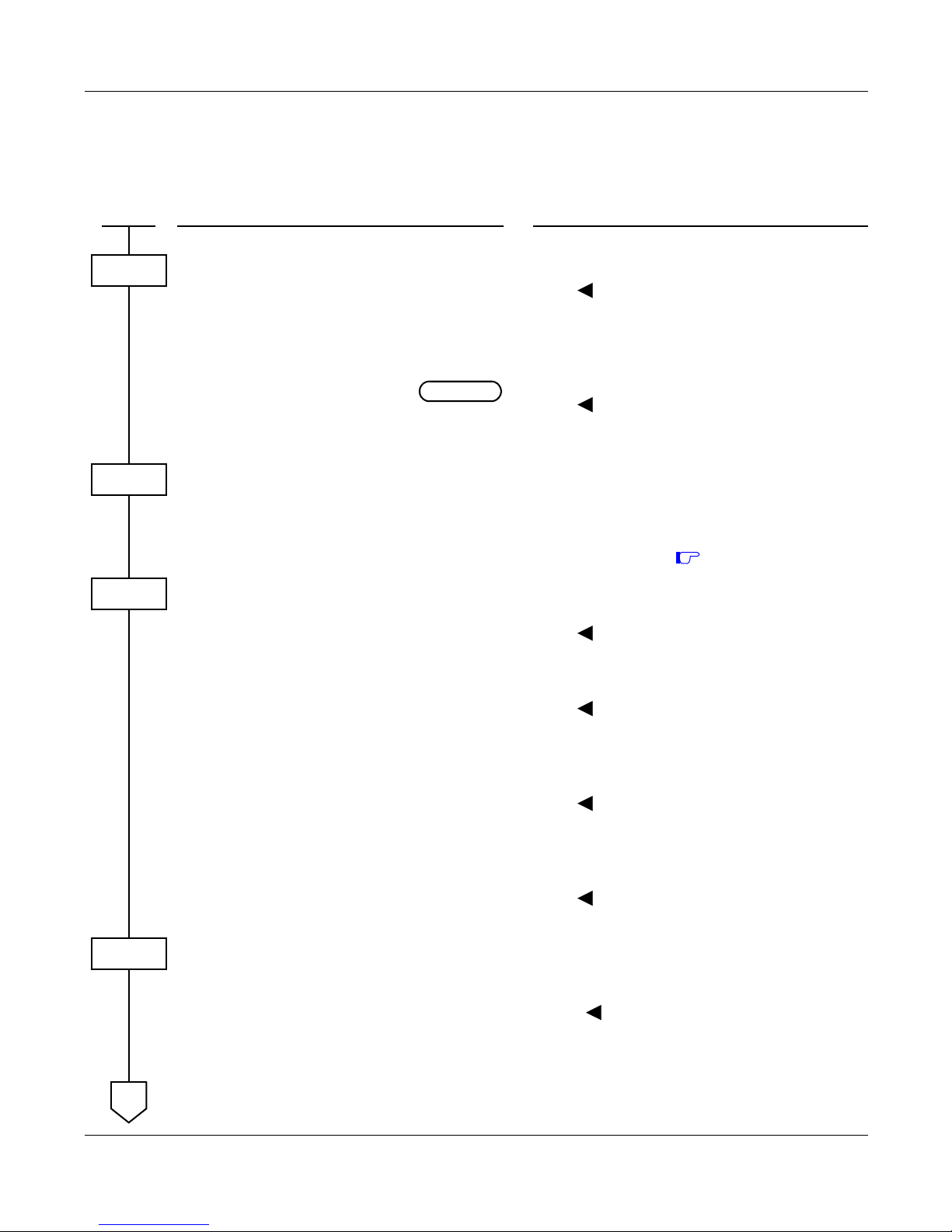
– 25 – NWA-008845-001 Rev.5.0
32ch1001.fm
ALPHANUMERIC DISPLAY
PROGRAMMING
DESCRIPTION DATA
Provide the system with the Name Display
Service.
(1)
(2)
255
1: To provide
Provide station number and name display
when an incoming call terminates to a Prime
Line and a My Line.
(1)
(2)
335
0 : Station No. and name display only
when incoming call terminates to
Prime Line
1 : Station No. and name display when in-
coming call terminates to Prime Line
or My line
Assign the access code for Name Display. •
(1)
(2)
Y=0-3 Numbering Plan Group 0-3
X-XXXX: Access Code (62)
A110
See NAME DISPLAY REGISTRATION
FROM D
term
. Page 53
Specify the time to go back to Date and Time
display after the call answered.
(1)
(2)
120
0 : 10 seconds later
1 : 6 seconds later
Specify the duration to display the name. (1)
(2)
121
0 : Until call finished
1 : As per CM08>120
Specify the duration of displaying the name
when the incoming call is answered/the select
key for Calling Number Display and Calling
Name Display or CID key is pressed.
[Series 3300 software required]
(1)
(2)
537
0 : Until call is finished/key is pressed
again
1 : 6 seconds
Specify the duration of displaying the destination information when the outgoing call is answered by the destination via CCIS/ISDN.
[Series 3300 software required]
(1)
(2)
538
0 : Until call is finished
1 : 6 seconds
Assign a trunk name number to each trunk
route.
•
(1)
(2)
Y=03
00-63: Trunk Route No.
00-14: Trunk Name No. 00-14
15 : Kind of trunk route assigned by
CM35 Y=00 is displayed
16-63: Trunk Name No. 16-63
START
CM08
INITIAL
CM20
CM08
CM35
A
JANUARY/20/2006
ALPHANUMERIC DISPLAY
Page 44

– 26 – NWA-008845-001 Rev.5.0
32ch1001.fm
NOTE 1: The maximum number of stations that can be provided with the user’s name display is 512. The
maximum number of characters per name is eight, including spaces. The Maintenance Administration Terminal (MAT) or Customer Administration Terminal (CAT) can be used to register
or change a name. A D
term
can register or change the name assignment of that individual D
term
.
NOTE 2: User names can be assigned to stations that do not have an LCD.
NOTE 3: The trunk name display is provided on a trunk-route basis. The maximum amount of characters
in the trunk name display is four. The maximum number of trunk routes assignable is 16. The
MAT or CAT can be used to register or change a trunk name display.
NOTE 4: There are two ways to change a name that is currently programmed. (1) by overwriting with a
new name, or (2) by inserting a blank space as the first character to cancel the existing name.
DESCRIPTION DATA
Enter the desired station user’s name to each
station number by CM77 Y=0 or CM77 Y=1.
•
(1)
(2)
Y=0 By Character Code
X-XXXXXXXX: Station No.
Character Code 20-7F (Maximum 32 digits)
See APPENDIX B: Character Code Table.
Page B2
•
(1)
(2)
Y=1 By Character
X-XXXXXXXX: Station No.
A-Z, 0-9: Character
(Maximum 16 characters)
Assign the desired trunk name to each trunk
route by CM77 Y=2 or CM77 Y=3.
•
(1)
(2)
Y=2 By Character Code
00-14, 16-63: Trunk Name No. assigned by
CM35 Y=03
Character Code 20-7F (Maximum 8 digits)
See APPENDIX B: Character Code Table.
Page B2
•
(1)
(2)
Y=3 By Character
00-14, 16-63: Trunk Name No. assigned by
CM35 Y=03
A-Z, 0-9: Character
(Maximum 4 characters)
A
CM77
END
JANUARY/20/2006
ALPHANUMERIC DISPLAY
Page 45
– 27 – NWA-008845-001 Rev.5.0
32ch1001.fm
To display the Caller ID for each D
term
before answer when an incoming call is terminated with TAS, do
the following programming.
[Series 3600 software required]
NOTE: This programming is effective only when CM76 Y=01-04 is set to D03 (Trunk Line [Direct] Ap-
pearance + TAS)/D13 (TAS), or CM30 Y=02/04/40/41 is set to 03 (Trunk Line [Direct] Appearance + TAS)/13 (TAS).
DESCRIPTION DATA
Provide Caller ID Display for each tenant
when an incoming call is terminated to a D
term
with TAS.
•
(1)
(2)
Y=42
00-63: Tenant No.
0: To provide
1: Not provided
Specify the My Line number of D
term
that dis-
plays the caller ID.
NOTE: The number of stations that can dis-
play the caller ID on LCD is maximum 8 per tenant.
Set the allocation number to the stations that displays the caller ID.
•
(1)
(2)
Y=30
XX YY
XX: 00-63: Tenant No.
YY: 00-07: Allocation No.
X-XXXXXXXX: My Line No.
Provide Caller ID Display for the my line assigned by CM57 Y=30.
•
(1)
(2)
Y=54
X-XXXXXXXX: My Line No.
0: To provide
1: Not provided
Assign the TAS Answer keys to the D
term
.•
(1)
(2)
Y=00
My Line No. + + Key No.
F40XX
XX: 00-63: Tenant No. assigned by CM57
Y=30
START
CM65
CM57
CM13
CM90
,
END
JULY/01/2006
ALPHANUMERIC DISPLAY
Page 46
– 28 – NWA-008845-001 Rev.5.0
32ch1001.fm
To display the Caller ID for each D
term
before answer when an incoming call is terminated to a sub line,
do the following programming.
[Series 3600 software required]
DESCRIPTION DATA
Provide Caller ID Display for each tenant
when an incoming call is terminated to a sub
line of D
term
.
•
(1)
(2)
Y=43
00-63: Tenant No.
0: To provide
1: Not provided
Specify the My Line number of D
term
that dis-
plays the caller ID.
NOTE: The number of stations that can dis-
play the caller ID on LCD is maximum 8 per tenant.
Assign the allocation number to the
stations that displays the caller ID.
•
(1)
(2)
Y=30
XX YY
XX: 00-63: Tenant No.
YY: 00-07: Allocation No.
X-XXXXXXXX: My Line No.
Provide Caller ID Display for the my line assigned by CM57 Y=30.
•
(1)
(2)
Y=54
X-XXXXXXXX: My Line No.
0: To provide
1: Not provided
Provide Caller ID Display for the stations of
SLT/sub line of D
term
/Virtual line/Virtual sta-
tion for PS that are accommodated to the D
term
multiline as a sub line.
NOTE: When terminating the call to the sta-
tions of SLT/sub line of D
term
/Virtual line/Virtual station for PS, the
caller ID is displayed on the LCD of
the D
term
assigned by CM57 Y=30.
•
(1)
(2)
Y=55
X-XXXXXXXX: Station No.
0: To provide
1: Not provided
START
CM65
CM57
CM13
END
JULY/01/2006
ALPHANUMERIC DISPLAY
Page 47
– 29 – NWA-008845-001 Rev.5.0
32ch1001.fm
ANALOG PORT ADAPTER
PROGRAMMING
To assign the Single Port Mode:
To assign the Dual Port Mode:
(1) Data Assignment for D
term
accommodates the Analog Port Adapter
DESCRIPTION DATA
Provide the Analog Port Adapter to the
required stations.
•
(1)
(2)
Y=32
X-XXXXXXXX: My Line No.
0: To connect
Assign the Single Port Mode to the required
stations.
•
(1)
(2)
Y=33
X-XXXXXXXX: My Line No.
1 : Single port mode
Specify whether a ringing signal is sent to the
analog terminal.
•
(1)
(2)
Y=35
X-XXXXXXXX: My Line No.
0: Not sent
1: To send
DESCRIPTION DATA
Provide the Analog Port Adapter to the
required stations.
•
(1)
(2)
Y=32
X-XXXXXXXX: My Line No.
0: To connect
Assign the Dual Port Mode to the required
stations.
•
(1)
(2)
Y=33
X-XXXXXXXX: My Line No.
0: Dual port mode
START
CM13
INITIAL
END
START
CM13
INITIAL
END
ANALOG PORT ADAPTER
Page 48

– 30 – NWA-008845-001 Rev.5.0
32ch1001.fm
(2) Data Assignment for Analog Terminal connected to the Analog Port Adapter
DESCRIPTION DATA
Assign an analog terminal station number to
the required LEN.
NOTE: The analog terminal station number
must be assigned to the following
LEN.
Analog Terminal LEN=D
term
LEN
+ 8.
For example, when the DLC card is
mounted on LT01 slot;
For D
term
LEN: 008-015
For Analog Terminal LEN: 016023*
*LT02 slot must be vacant.
(1)
(2)
000-763: LEN
FX-FXXXXXXXX: Analog Terminal
Station No.
Assignment Example:
CM10 LEN 000=F 200 for D
term
Primary Extension
CM10 LEN 008=F 300 for Analog Terminal
If level 0 of the LEN is used for the D
term
, the adjacent level 0 must be used.
Assign an analog terminal station number to
the required LEN.
[Series 3200 R6.2 software required]
NOTE: The analog terminal station number
must be assigned to the following
LEN.
Analog Terminal LEN=D
term
LEN
+ 8.
For example, when the DLC card is
mounted on LT01 slot;
For D
term
LEN: 00008-00015
For Analog Terminal LEN:
00016-00023*
*LT02 slot must be vacant.
(1)
(2)
XX ZZZ: LEN
XX : 00-59: FP No.
ZZZ: 000-127: Port No.
FX-FXXXXXXXX: Analog Terminal
Station No.
Assignment Example:
CM14 LEN 00000=F 200 for D
term
Primary Extension
CM14 LEN 00008=F 300 for Analog Terminal
If level 0 of the LEN is used for the D
term
, the adjacent level 0 must be used.
START
CM10
CM14
A
ANALOG PORT ADAPTER
Page 49
– 31 – NWA-008845-001 Rev.5.0
32ch1001.fm
HARDWARE REQUIRED
Analog Port Adapter
DESCRIPTION DATA
Assign a key for analog terminal. •
(1)
(2)
Y=00
Analog Terminal Station No. + + Key
No.
X-XXXXXXXXXX: Analog Terminal
Station No. assigned
by CM10/CM14
Assign an analog terminal station number as
Prime Line.
(1)
(2)
X-XXXXXXXX: Analog Terminal Station
No.
X-XXXXXXXX: Analog Terminal Station
No.
Provide the Analog Port Adapter to the
required stations.
•
(1)
(2)
Y=34
X-XXXXXXXX: Analog Terminal Station
No.
0: To connect
Specify whether a ringing signal is sent to the
analog terminal.
•
(1)
(2)
Y=35
X-XXXXXXXX: My Line No.
0: Not sent
1: To send
Specify the PAD control of the analog
terminal.
•
(1)
(2)
Y=09
X-XXXXXXXX: Analog Terminal Station
No.
0 : Without PAD
1 : With PAD 6dB
A
CM90
,
CM93
CM13
END
JULY/01/2006
ANALOG PORT ADAPTER
Page 50
– 32 – NWA-008845-001 Rev.5.0
32ch1001.fm
ANNOUNCEMENT SERVICE
PROGRAMMING
To access the Digital Announcement Trunk (DAT card) from a station or C.O./Tie Line party:
DESCRIPTION DATA
Specify the Multiple Connections of the
Digital Announcement Trunk (DAT card) on
Announcement Service.
(1)
(2)
124
0 : Available
1 : Not available (Single Connection)
Assign a Digital Announcement Trunk number
to the required LEN.
NOTE 1: The Digital Announcement Trunk
number must be assigned to the first
LEN (Level 0), the third LEN (Level
2), the fifth LEN (Level 4) and the
seventh LEN (Level 6) of each LT
slot.
(1)
(2)
000-763: LEN
EB002-EB127: Digital Announcement
Trunk No.
For PIM0/1 : EB002-EB031
For PIM2/3 : EB032-EB063
For PIM4/5 : EB064-EB095
For PIM6/7 : EB096-EB127
NOTE 2: EB000 and EB001 are dedicated to
built-in Digital Announcement Trunk
of the MP card.
Assign a Digital Announcement Trunk number
to the required LEN.
[Series 3200 R6.2 software required]
NOTE 1: The Digital Announcement Trunk
number must be assigned to the first
LEN (Level 0), the third LEN (Level
2), the fifth LEN (Level 4) and the
seventh LEN (Level 6) of each LT
slot.
(1)
(2)
XX ZZZ: LEN
XX : 00-59: FP No.
ZZZ: 000-127: Port No.
EB002-EB127: Digital Announcement
Trunk No.
For FP No. 00 : EB002-EB031
For FP No. 01 : EB032-EB063
For FP No. 02 : EB064-EB095
For FP No. 03 : EB096-EB127
NOTE 2: EB000 and EB001 are dedicated to
built-in Digital Announcement Trunk
of the MP card.
Assign Service Restriction Class A for Announcement Service to the required stations.
•
(1)
(2)
Y=02
X-XXXXXXXX: My Line No.
XX ZZ
XX: 00-15 : Service Restriction Class A
START
CM08
CM10
CM14
CM12
A
ANNOUNCEMENT SERVICE
Page 51
– 33 – NWA-008845-001 Rev.5.0
32ch1001.fm
DESCRIPTION DATA
Allow Announcement Service in Service
Restriction Class A assigned by CM12 Y=02.
•
•
•
•
•
•
(1)
(2)
Y=34 Announcement Service Group 0
(Replay)
Y=35 Announcement Service Group 1
(Replay)
Y=36 Announcement Service Group 2
(Replay)
Y=37 Announcement Service Group 3
(Replay)
Y=38 Announcement Service Group 4
(Replay)
Y=39 Announcement Service Group 0-4
(Record)
00-15: Service Restriction Class A as-
signed by CM12 Y=02
1 : Allow
Assign access codes for Announcement Service.
•
(1)
(2)
Y=0-3 Numbering Plan Group 0-3
X-XXXX: Access Code
A103: Announcement Service Group 0-4
(Record)
A104: Announcement Service Group 0
(Replay)
A105: Announcement Service Group 1
(Replay)
A106: Announcement Service Group 2
(Replay)
A107: Announcement Service Group 3
(Replay)
A108: Announcement Service Group 4
(Replay)
A109: Announcement Service Group 0-4
(Delete)
When Multiple Connections are provided
(CM08>124=0), specify the duration of
message replay for the Announcement Service.
•
(1)
(2)
Y=0
53
01-99: 4-396 seconds
(4 second increments)
If no data is set, the default setting is 60-64
seconds.
A
CM15
CM20
CM41
B
JULY/01/2006
ANNOUNCEMENT SERVICE
Page 52

– 34 – NWA-008845-001 Rev.5.0
32ch1001.fm
NOTE 1: A maximum of five different announcements can be accessed. There is a limit of 10 Digital An-
nouncement Trunk Circuit for each of the five different announcements. When recording an announcement, each Digital Announcement Trunk Circuit must be recorded individually.
NOTE 2: Each time a station is connected to a Digital Announcement Trunk Circuit, the message will be
repeated three times. The station will then be disconnected.
NOTE 3: For the single connection of a Digital Announcement Trunk Circuit, the duration of an an-
nouncement is limited to 120 seconds.
NOTE 4: For the multi-connection of a Digital Announcement Trunk Circuit, the duration of replay for
an announcement is programmable from 4 to 396 seconds.
DESCRIPTION DATA
Assign the function for each Digital
Announcement Trunk card.
•
(1)
(2)
Y=00
000-001: Built-in DAT on MP card
002-127: Digital Announcement Trunk No.
(EB002-EB127)
04X Z
X: 0-4: Group No.
Z: 0-9: Message No.
To provide a C.O./Tie Line party with this
service, assign the Announcement Service
Group 0-4 to the required trunk routes.
•
•
•
•
•
(1)
(2)
Y=69 Announcement Service Group 0
Y=70 Announcement Service Group 1
Y=71 Announcement Service Group 2
Y=72 Announcement Service Group 3
Y=73 Announcement Service Group 4
00-63: Trunk Route No.
1 : Allow
B
CM49
CM35
END
ANNOUNCEMENT SERVICE
Page 53
– 35 – NWA-008845-001 Rev.5.0
32ch1001.fm
To provide a voice message when an incoming C.O. line/Tie line call has been transferred and encounters
a busy or no answer condition:
DESCRIPTION DATA
Assign a Digital Announcement Trunk card
number to the required LEN.
NOTE 1: The Digital Announcement Trunk
Circuit number must be assigned to
the first LEN (Level 0), the third
LEN (Level 2), the fifth LEN (Level
4) and the seventh LEN (Level 6) of
each LT slot.
(1)
(2)
000-763: LEN
EB002-EB127: Digital Announcement
Trunk Card No.
For PIM0/1 : EB002-EB031
For PIM2/3 : EB032-EB063
For PIM4/5 : EB064-EB095
For PIM6/7 : EB096-EB127
NOTE 2: EB000 and EB001 are dedicated to
built-in Digital Announcement Trunk
of the MP card.
Assign a Digital Announcement Trunk card
number to the required LEN.
[Series 3200 R6.2 software required]
NOTE 1: The Digital Announcement Trunk
Circuit number must be assigned to
the first LEN (Level 0), the third
LEN (Level 2), the fifth LEN (Level
4) and the seventh LEN (Level 6) of
each LT slot.
(1)
(2)
XX ZZZ: LEN
XX : 00-59: FP No.
ZZZ: 000-127: Port No.
EB002-EB127: Digital Announcement
Trunk Card No.
For FP No. 00 : EB002-EB031
For FP No. 01 : EB032-EB063
For FP No. 02 : EB064-EB095
For FP No. 03 : EB096-EB127
NOTE 2: EB000 and EB001 are dedicated to
built-in Digital Announcement Trunk
of the MP card.
Assign Service Restriction Class A for Digital
Announcement Trunk Access
(Record/Replay/Delete).
•
(1)
(2)
Y=02
X-XXXXXXXX: Station No.
XX ZZ
XX: 00-15 : Service Restriction Class A
Allow Digital Announcement Trunk Access in
Service Restriction Class A assigned by CM12
Y=02.
•
(1)
(2)
Y=33
00-15: Service Restriction Class A as-
signed by CM12 Y=02
1 : Allow
Assign the feature for a voice message
connection to a transferred trunk when the
transferred destination does not answer or the
transferred destination is busy to the required
tenant.
•
(1)
(2)
Y=50 No Answer
00-63: Tenant No.
0
•
(1)
(2)
Y=51 Busy
00-63: Tenant No.
0
START
CM10
CM14
CM12
CM15
CM65
A
ANNOUNCEMENT SERVICE
Page 54

– 36 – NWA-008845-001 Rev.5.0
32ch1001.fm
NOTE: Announcement Service can be used to provide a voice message when an incoming C.O. line/Tie
line call has been transferred and encounters a busy or no answer condition. After the voice
message is given, normal call processing continues.
• This application can be programmed on a tenant basis.
• Only one (1) message of up to the following seconds can be recorded on an individual Digital
Announcement Trunk Circuit.
Built-in DAT on MP: 120 seconds
4DAT card: 120 seconds
• In this application, a minimum of two digital announcement Trunk Circuits is needed, one for
busy condition, and one for no answer.
• More than one Digital Announcement Trunk Circuit can be used, depending on traffic conditions.
• System programming can be set to, wait until circuits become free or immediately follow preprogrammed normal call handling, if a busy condition is encountered.
• Digital Announcement Trunk Circuits can be shared among tenants.
• This feature does not function on Attendant transferred calls.
DESCRIPTION DATA
Assign the function for each Digital Announcement Trunk card.
•
(1)
(2)
Y=00
000-001: Built-in DAT on MP card
002-127: Digital Announcement Trunk No.
(EB002-EB127)
06XX: No Answer
XX : 00-63: Message No.
07XX: Busy
XX : 00-63: Message No.
•
•
(1)
(2)
Y=06 No Answer
Y=07 Busy
XX: 00-63: Tenant No. of transferring
station
XX: 00-63: Message No. assigned by
CM49 Y=00
To record, replay and delete a message, assign
the respective Digital Announcement Trunk
access code.
•
(1)
(2)
Y=0-3 Number Plan Group 0-3
X-XXXX: Access Code
A100: Record
A101: Replay
A102: Delete
A
CM49
CM20
END
JULY/01/2006
ANNOUNCEMENT SERVICE
Page 55
– 37 – NWA-008845-001 Rev.5.0
32ch1001.fm
To provide a voice message when an incoming DID line/Tie line call has been terminated to a station and
encounters a busy or no answer condition:
DESCRIPTION DATA
Assign a Digital Announcement Trunk card
number to the required LEN.
NOTE 1: The Digital Announcement Trunk
card number must be assigned to the
first LEN (Level 0), the third LEN
(Level 2), the fifth LEN (Level 4) and
the seventh LEN (Level 6) of each
LT slot.
(1)
(2)
000-763: LEN
EB002-EB127: Digital Announcement
Trunk Card No.
For PIM0/1 : EB002-EB031
For PIM2/3 : EB032-EB063
For PIM4/5 : EB064-EB095
For PIM6/7 : EB096-EB127
NOTE 2: EB000 and EB001 are dedicated to
built-in Digital Announcement Trunk
of the MP card.
Assign a Digital Announcement Trunk card
number to the required LEN.
[Series 3200 R6.2 software required]
NOTE 1: The Digital Announcement Trunk
card number must be assigned to the
first LEN (Level 0), the third LEN
(Level 2), the fifth LEN (Level 4) and
the seventh LEN (Level 6) of each
LT slot.
(1)
(2)
XX ZZZ: LEN
XX : 00-59: FP No.
ZZZ: 000-127: Port No.
EB002-EB127: Digital Announcement
Trunk Card No.
For FP No. 00 : EB002-EB031
For FP No. 01 : EB032-EB063
For FP No. 02 : EB064-EB095
For FP No. 03 : EB096-EB127
NOTE 2: EB000 and EB001 are dedicated to
built-in Digital Announcement Trunk
of the MP card.
Assign Service Restriction Class A for Digital
Announcement Trunk Access
(Record/Replay/Delete).
•
(1)
(2)
Y=02
X-XXXXXXXX: Station No.
XX ZZ
XX: 00-15 : Service Restriction Class A
Allow Digital Announcement Trunk Access in
Service Restriction Class A assigned by CM12
Y=02.
•
(1)
(2)
Y=33
00-15: Service Restriction Class A as-
signed by CM12 Y=02
1 : Allow
Specify the transferred timing when an incoming DID Line/Tie Line call encounters a no answer condition.
•
(1)
(2)
Y=0
01
01-30: 4-120 seconds
(4 second increments)
If no data is set, the default setting is 32-36
seconds.
START
CM10
CM14
CM12
CM15
CM41
A
ANNOUNCEMENT SERVICE
Page 56
– 38 – NWA-008845-001 Rev.5.0
32ch1001.fm
NOTE: Announcement Service can be used to provide a voice message when an incoming DID line/Tie
line call has been terminated to a station and encounters a busy or no answer condition. After
the voice message is given, normal call processing continues.
• This application can be programmed on a tenant basis.
• Only one (1) message of up to the following seconds can be recorded on an individual Digital
Announcement Trunk Circuit.
Built-in DAT on MP: 120 seconds
4DAT card: 120 seconds
DESCRIPTION DATA
Assign the function for each Digital
Announcement Trunk card.
•
(1)
(2)
Y=00
000-001: Built-in DAT on MP card
002-127: Digital Announcement Trunk No.
(EB002-EB127)
0D00: No Answer
0E00: Busy
Assign the Digital Announcement Trunk as the
destination of the DID call on each tenant.
•
•
(1)
(2)
Y=00 No Answer
Y=03 Busy
00-63: Tenant No.
EB000-EB127: Digital Announcement
Trunk No.
Assign the Digital Announcement Trunk as the
destination of the Tie Line call on each tenant.
•
•
(1)
(2)
Y=01 No Answer
Y=04 Busy
00-63: Tenant No.
EB000-EB127: Digital Announcement
Trunk No.
To record, replay and delete a message, assign
the respective Digital Announcement Trunk
access code.
•
(1)
(2)
Y=0-3 Number Plan Group 0-3
X-XXXX: Access Code
A100: Record
A101: Replay
A102: Delete
A
CM49
CM51
CM20
END
ANNOUNCEMENT SERVICE
Page 57
– 39 – NWA-008845-001 Rev.5.0
32ch1001.fm
To provide an Internal Recorded Message from a Digital Announcement Trunk (DAT card) in place of Music On Hold:
DESCRIPTION DATA
Assign a Digital Announcement Trunk card
number to the required LEN.
NOTE 1: The Digital Announcement Trunk
card number must be assigned to the
first LEN (Level 0), the third LEN
(Level 2), the fifth LEN (Level 4) and
the seventh LEN (Level 6) of each
LT slot.
(1)
(2)
000-763: LEN
EB002-EB127: Digital Announcement
Trunk Card No.
For PIM0/1 : EB002-EB031
For PIM2/3 : EB032-EB063
For PIM4/5 : EB064-EB095
For PIM6/7 : EB096-EB127
NOTE 2: EB000 and EB001 are dedicated to
built-in Digital Announcement Trunk
of the MP card.
Assign a Digital Announcement Trunk card
number to the required LEN.
[Series 3200 R6.2 software required]
NOTE 1: The Digital Announcement Trunk
card number must be assigned to the
first LEN (Level 0), the third LEN
(Level 2), the fifth LEN (Level 4) and
the seventh LEN (Level 6) of each
LT slot.
(1)
(2)
XX ZZZ: LEN
XX : 00-59: FP No.
ZZZ: 000-127: Port No.
EB002-EB127: Digital Announcement
Trunk Card No.
For FP No. 00 : EB002-EB031
For FP No. 01 : EB032-EB063
For FP No. 02 : EB064-EB095
For FP No. 03 : EB096-EB127
NOTE 2: EB000 and EB001 are dedicated to
built-in Digital Announcement Trunk
of the MP card.
Define the type of call to be provided with
Hold Message.
•
(1)
(2)
Y=0
00: C.O. Line Call
01: Tie Line Call
02: Station
0500: Hold Message
Assign the function of the Digital Announcement Trunk to Hold Message Service.
•
(1)
(2)
Y=00
000-001: Built-in DAT on MP card
002-127: Digital Announcement Trunk No.
(EB002-EB127) assigned by
CM10/CM14
05XX: Hold Message Service
XX : 00-63: Message No.
•
(1)
(2)
Y=05
00-63: Tenant No.
00-63: Message No. assigned by CM49
Y=00
START
CM10
CM14
CM48
CM49
A
ANNOUNCEMENT SERVICE
Page 58

– 40 – NWA-008845-001 Rev.5.0
32ch1001.fm
NOTE: A voice message in place of Music-On-Hold can be provided when a call has been placed on
hold.
• Different messages can be programmed on a tenant basis.
• Different messages can be programmed, depending on the type of line (C.O. line, Tie line or
station) on Hold.
• More than one connection can be made to a Digital Announcement Trunk Circuit. Only the
first connection can be assured of hearing the message from the beginning.
• Announcement will be repeated until the call is removed from hold.
DESCRIPTION DATA
To record, replay, or delete a message, assign
the respective Digital Announcement Trunk
access code.
•
(1)
(2)
Y=0-3 Number Plan Group 0-3
X-XXXX: Access Code
A100: Record
A101: Replay
A102: Delete
CM20
A
END
ANNOUNCEMENT SERVICE
Page 59
– 41 – NWA-008845-001 Rev.5.0
32ch1001.fm
To provide the Night Announcement by Digital Announcement Trunk (DAT card):
DESCRIPTION DATA
Assign each Digital Announcement Trunk
card number to the required LEN.
NOTE 1: The Digital Announcement Trunk
card number must be assigned to the
first LEN (Level 0), the third LEN
(Level 2), the fifth LEN (Level 4) and
the seventh LEN (Level 6) of each
LT slot.
(1)
(2)
000-763: LEN
EB002-EB127: Digital Announcement
Trunk Card No.
For PIM0/1 : EB002-EB031
For PIM2/3 : EB032-EB063
For PIM4/5 : EB064-EB095
For PIM6/7 : EB096-EB127
NOTE 2: EB000 and EB001 are dedicated to
built-in Digital Announcement Trunk
of the MP card.
Assign each Digital Announcement Trunk
card number to the required LEN.
[Series 3200 R6.2 software required]
NOTE 1: The Digital Announcement Trunk
card number must be assigned to the
first LEN (Level 0), the third LEN
(Level 2), the fifth LEN (Level 4) and
the seventh LEN (Level 6) of each
LT slot.
(1)
(2)
XX ZZZ: LEN
XX : 00-59: FP No.
ZZZ: 000-127: Port No.
EB002-EB127: Digital Announcement
Trunk Card No.
For FP No. 00 : EB002-EB031
For FP No. 01 : EB032-EB063
For FP No. 02 : EB064-EB095
For FP No. 03 : EB096-EB127
NOTE 2: EB000 and EB001 are dedicated to
built-in Digital Announcement Trunk
of the MP card.
Assign the Digital Announcement Trunk number to each incoming trunk.
•
(1)
(2)
Y=03
000-255: Trunk No.
04: Direct-In Termination
•
(1)
(2)
Y=05
000-255: Trunk No.
EB000-EB127: Digital Announcement
Trunk No. assigned by
CM10/CM14
Assign the function of the Digital Announcement Trunk to Night Announcement.
•
(1)
(2)
Y=00
000-001: Built-in DAT on MP card
002-127: Digital Announcement Trunk No.
(EB002-EB127)
03000: Night Announcement Service
START
CM10
CM14
CM30
CM49
A
ANNOUNCEMENT SERVICE
Page 60

– 42 – NWA-008845-001 Rev.5.0
32ch1001.fm
NOTE: A voice message can be sent to incoming C.O. lines during Night Mode.
• Different messages can be programmed on each C.O. line.
• The voice message can be programmed for Day/Night.
• More than one connection can be made to a Digital Announcement Trunk Circuit. Only the
first connection can be assured of hearing the message from the beginning.
• Announcements may be programmed to be repeated from 4 to 120 seconds in four-second increments.
HARDWARE REQUIRED
DAT card or MP card (built-in DAT)
DESCRIPTION DATA
Specify the duration of an Announcement. •
(1)
(2)
Y=0
45
01-30: 4-120 seconds
(4 second increments)
If no data is set, the default setting is 60-64
seconds.
To record, replay, or delete a message, assign
the respective Digital Announcement Trunk
access code.
•
(1)
(2)
Y=0-3 (Numbering Plan Group 0-3)
X-XXXX: Access Code
A100: Record
A101: Replay
A102: Delete
A
CM41
CM20
END
ANNOUNCEMENT SERVICE
Page 61
– 43 – NWA-008845-001 Rev.5.0
32ch1001.fm
ANSWER KEY
PROGRAMMING
NOTE: An ANSWER key is initially assigned on each D
term
.
HARDWARE REQUIRED
D
term
and DLC card
DESCRIPTION DATA
Assign Service Restriction Class B for Answer
Key to the required D
term
.
•
(1)
(2)
Y=02
X-XXXXXXXX: My Line No.
XX ZZ
ZZ: 00-15 :
Service Restriction Class B
Allow Answer Key in Service Restriction
Class B assigned by CM12 Y=02.
•
(1)
(2)
Y=72
00-15: Service Restriction Class B as-
signed by CM12 Y=02
0: Allow
START
CM12
CM15
END
ANSWER KEY
Page 62
– 44 – NWA-008845-001 Rev.5.0
32ch1001.fm
ATTENDANT ASSISTED CALLING
PROGRAMMING
DESCRIPTION DATA
Assign the Access code for an operator call. •
(1)
(2)
Y=0-3 Numbering Plan Group 0-3
X-XXXX: Access Code (0)
800
Allocate the ATTCON Group number to each
DESKCON.
•
(1)
(2)
Y=00
0-7: ATTCON No. assigned by CM10/
CM14
0-3: ATTCON Group No.
Assign the Master ATTCON within the
ATTCON Group.
•
(1)
(2)
Y=01
0-7: ATTCON No.
0 : Master ATT
1: Not Master ATT
Specify the tenants to be handled by each ATT
Group.
•
(1)
(2)
Y=0-3 ATTCON Group No. 0-3 assigned
by CM60 Y=00
00-63: Tenant No.
0: To be handled
Specify the Attendant access (ATTCON No.
0) capability provided from the stations belonging to a tenant with no Attendant Console.
(1)
(2)
142
0 : Allowed
1 : Restricted
Provide the system with Passing Dial Tone. (1)
(2)
048
1 : Available
Provide the system with Attendant Night
Transfer, if required.
(1)
(2)
018
0 : Not available
1 : Available
Specify the Individual Attendant access
capability provided from a station belonging to
a different tenant.
(1)
(2)
143
0 : Restricted
1 : Allowed
START
CM20
CM60
INITIAL
INITIAL
CM62
INITIAL
CM08
END
ATTENDANT ASSISTED CALLING
Page 63
– 45 – NWA-008845-001 Rev.5.0
32ch1001.fm
ATTENDANT CAMP-ON
PROGRAMMING
To reenter a Camped-On trunk from an Attendant before Automatic Recall:
DESCRIPTION DATA
Specify Attendant Camp-On as a type of
Camp-On to activate from the Attendant Console.
[Series 3400 software required]
(1)
(2)
542
1 : Attendant Camp-On
Specify the Camp-On Tone sent to busy
station
(1)
(2)
068
0 : Camp-on Tone is sent out only once.
1 : Camp-on Tone is repeated at an inter-
val of 4 seconds.
Specify the recall timing of Camp-On. •
(1)
(2)
Y=0
00
01-14: 2.4-33.6 seconds
(2.4 second increments)
15-24: 38.4-124.8 seconds
(9.6 second increments)
If no data is set, the default setting is 31.2-33.6
seconds.
DESCRIPTION DATA
Assign the access code for Call Pickup-Direct. •
(1)
(2)
Y=0-3 Numbering Plan Group 0-3
X-XXXX: Access Code
A021: Call Pickup-Direct
START
CM08
CM41
END
START
CM20
END
ATTENDANT CAMP-ON
Page 64

– 46 – NWA-008845-001 Rev.5.0
32ch1001.fm
To display the busy station number and name on an Attendant Console when reentering a Camped-On
trunk by pressing the loop key:
DESCRIPTION DATA
Provide the Attendant Console with the busy
station number/name display when reentering
a Camped-On trunk.
(1)
(2)
441
0 : Available
1 : Not available
START
CM08
END
ATTENDANT CAMP-ON
Page 65
– 47 – NWA-008845-001 Rev.5.0
32ch1001.fm
ATTENDANT CONSOLE
SN716 DESKCON
PROGRAMMING
DESCRIPTION DATA
Assign the card number of the interface circuit
for the DESKCON to its associated LEN.
(1)
(2)
000-763: LEN
E000-E007: ATTCON No.
Assign the card number of the interface circuit
for the DESKCON to its associated LEN.
[Series 3200 R6.2 software required]
(1)
(2)
XX ZZZ: LEN
XX : 00-59: FP No.
ZZZ: 000-127: Port No.
E000-E007: ATTCON No.
Set the terminating system for the incoming
calls to DESKCON.
•
•
•
•
(1)
(2)
Y=02 Day Mode
Y=03 Night Mode
Y=40 Mode A
Y=41 Mode B
000-255: Trunk No.
14: Attendant Console
Assign the required Attendant Call Selection
keys and Function keys to each DESKCON,
according to the key label. To assign MultiFunction Key, refer to MULTI-FUNCTION
KEY. Page 73
•
(1)
(2)
Y=00
ATTCON No. (E000-E007) + + Key
No.
F6000-F6067: Type of Calls to be assigned
F6100-F6245: Functions to be assigned
START
CM10
CM14
CM30
CM90
,
A
ATTENDANT CONSOLE
SN716 DESKCON
Page 66
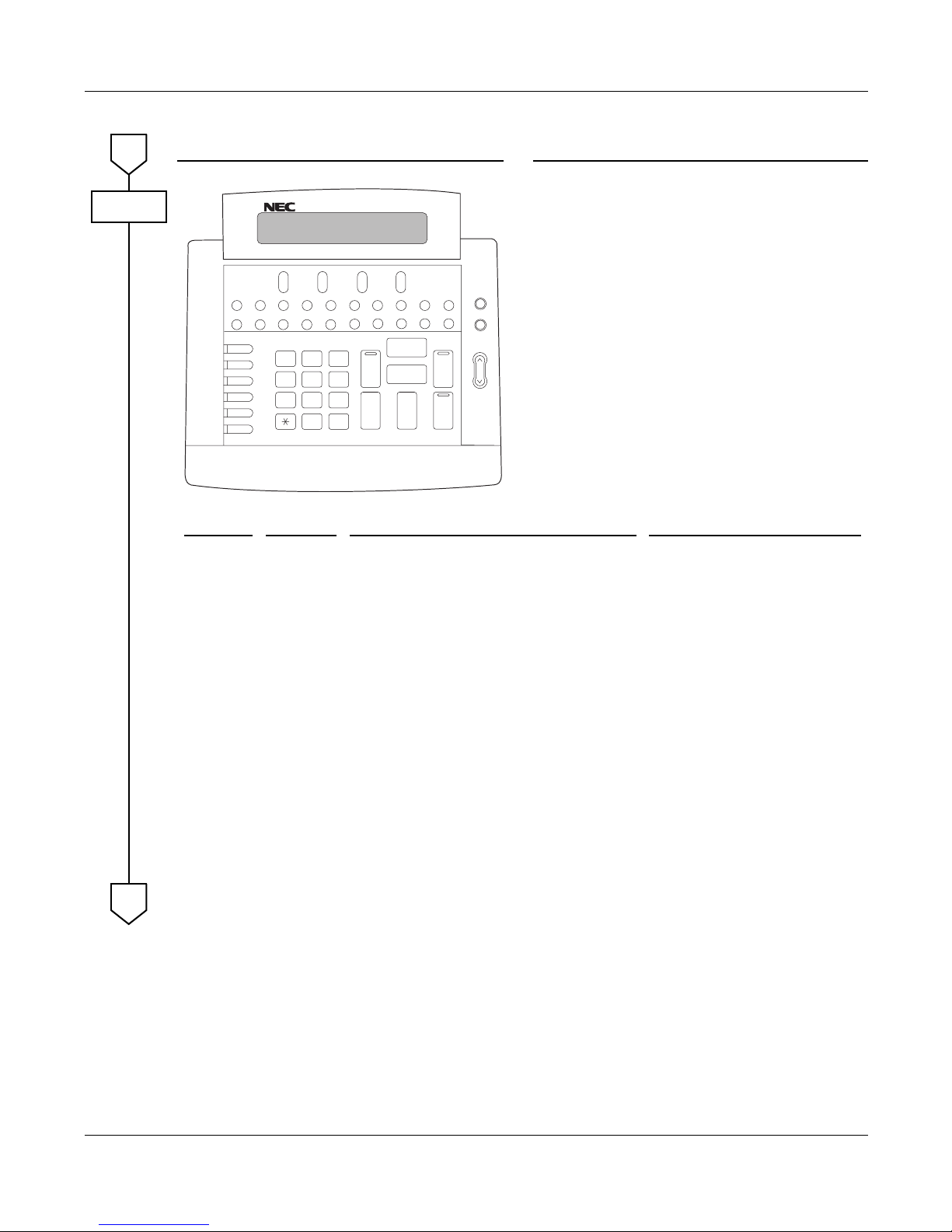
– 48 – NWA-008845-001 Rev.5.0
32ch1001.fm
DESCRIPTION DATA
NOTE: When the DESKCON is used to set hotel features, the Reset key should be assigned to one
of the feature keys (i.e key 21) in the Idle state mode.
A
CM90
L6 (12)
L5 (11)
L4 (10)
L3 (09)
L2 (08)
L1 (07)
0
89
6
3
5
2
1
4
7
#
SRC
(90)
DEST
(91)
(93)
(95)
Answer
(96)
Hold
(94)
Release
(97)
Cancel
Talk
Position Busy
Volume
Night
(15)
(01) (02) (03)
(04)
(13) (16) (17) (18) (92) (19) (20) (21)(14)
(24)(22)
(23)
LDN TIE Busy ATND NANS Recall
EMG BV TRKSL Call Park SC SVC
REC
Mute
PAGE
Start
Key No. Data Description (Key Label) Default Data
13
14
15
16
17
18
90
91
93
94
95
96
97
F6000
F6040
F6064
F6060
F6063
F6061
F6200
F6201
F6203
F6204
F6202
C.O. Incoming 0 (LDN)
Tie Line Incoming 0 (TIE)
Call Forwarding-Busy Line (Busy)
Operator Call (ATND)
Call Forwarding-No Answer (NANS)
Recall (Recall)
Source (SRC)
Destination (DEST)
Talk (Talk )
Hold (Hold)
Cancel (Cancel)
Answer (Answer)
Release (Release)
NONE
NONE
NONE
F6061 (Recall)
F6060 (Operator call)
F6000 (C.O. Incoming 0)
F6200 (Source)
F6201 (Destination)
NONE
F6204 (Hold)
F6202 (Cancel)
B
ATTENDANT CONSOLE
SN716 DESKCON
Page 67
– 49 – NWA-008845-001 Rev.5.0
32ch1001.fm
DESCRIPTION DATA
Specify the kind of the Attendant Console. •
(1)
(2)
Y=22
0-7: ATTCON No.
0 : DESKCON
1: ATTCON
Allocate the ATT Group number to each
DESKCON.
•
(1)
(2)
Y=00
0-7: ATTCON No.
0-3: ATT GROUP 0-3
Specify the Master DESKCON within the ATT
Group assigned by CM60 Y=00.
•
(1)
(2)
Y=01
0-7: ATTCON No.
0 : Master ATT
1: Not Master ATT
When the Master DESKCON is specified by
CM60 Y=01, make the NT Switch in effective
by the Day/Night Mode Change key.
•
(1)
(2)
Y=06
0-7: ATTCON No.
0: Effective
Assign the password for Attendant Console
Lockout.
•
(1)
(2)
Y=30
0
X-X...X: Password (Maximum 8 digits)
X : 0-9, A (*), B (#)
If no data is set, the default setting is NONE.
In this case, the password is set to “12345678”.
When providing 2nd Ringing feature on the
DESKCON, make Off-Hook Ringing effective.
•
(1)
(2)
Y=16
0-7: ATTCON No.
0: Effective
Allow or restrict the system to keep the volume
level changed by the volume button on
DESKCON, after the call is finished.
•
(1)
(2)
Y=23
0-7: ATTCON No.
0 : Allow
1 : Restricted
B
CM60
INITIAL
INITIAL
INITIAL
INITIAL
C
ATTENDANT CONSOLE
SN716 DESKCON
Page 68

– 50 – NWA-008845-001 Rev.5.0
32ch1001.fm
DESCRIPTION DATA
Specify the tenants to be handled by each ATT
Group.
•
(1)
(2)
Y=0-3
00-63: Tenant No.
0 : To handle
1 : Not handled
C
CM62
INITIAL
END
DECEMBER/02/2005
ATTENDANT CONSOLE
SN716 DESKCON
Page 69
– 51 – NWA-008845-001 Rev.5.0
32ch1001.fm
ATTENDANT CALLED/CALLING NAME DISPLAY
PROGRAMMING
DESCRIPTION DATA
Provide the system with the Name Display
Service.
(1)
(2)
255
1: To provide
Specify the time to go back to Data and Time
display after the call answered.
(1)
(2)
120
0 : 10 seconds later
1 : 6 seconds later
Specify the duration to display the name. (1)
(2)
121
0 : Until call finished
1 : As per CM08>120
Specify the duration of displaying the name
when the incoming call is answered/the select
key for Calling Number Display and Calling
Name Display or CID key is pressed.
[Series 3300 software required]
(1)
(2)
537
0 : Until call is finished/key is pressed
again
1 : 6 seconds
Specify the duration of displaying the destination information when the outgoing call is answered by the destination via CCIS/ISDN.
[Series 3300 software required]
(1)
(2)
538
0 : Until call finished
1 : 6 seconds
Assign the access code for Name Display, used
from individual stations.
•
(1)
(2)
Y=0-3 Numbering Plan Group 0-3
X-XXXX: Access Code (62)
A110
See NAME DISPLAY REGISTRATION
FROM D
term
. Page 53
Assign a trunk name number to each trunk
route.
•
(1)
(2)
Y=03
00-63: Trunk Route No.
00-14: Trunk Name No. 00-14
15 : Kind of trunk route assigned by
CM35 Y=00 is displayed
16-63: Trunk Name No. 16-63
START
CM08
CM20
CM35
A
JANUARY/20/2006
ATTENDANT CONSOLE
ATTENDANT CALLED/CALLING NAME DISPLAY
Page 70

– 52 – NWA-008845-001 Rev.5.0
32ch1001.fm
DESCRIPTION DATA
Assign the desired station user name to each
station number by CM77 Y=0 or Y=1.
•
(1)
(2)
Y=0 By Character Code
X-XXXXXXXX: Station No.
Character Code 20-7F (Maximum 32 digits)
See APPENDIX B: Character Code Table.
Page B2
•
(1)
(2)
Y=1 By Character
X-XXXXXXXX: Station No.
A-Z, 0-9: Character
(Maximum 16 characters)
Assign the desired trunk name to each trunk
route by CM77 Y=2 or Y=3.
•
(1)
(2)
Y=2 By Character Code
00-14, 16-63: Trunk Name No. assigned by
CM35 Y=03
Character Code 20-7F (Maximum 8 digits)
See APPENDIX B: Character Code Table.
Page B2
•
(1)
(2)
Y=3 By Character
00-14, 16-63: Trunk Name No. assigned by
CM35 Y=03
A-Z, 0-9: Character
(Maximum 4 characters)
A
CM77
END
JANUARY/20/2006
ATTENDANT CONSOLE
ATTENDANT CALLED/CALLING NAME DISPLAY
Page 71
– 53 – NWA-008845-001 Rev.5.0
32ch1001.fm
NAME DISPLAY REGISTRATION FROM D
term
• You can configure the station number from the D
term
to which the station number belongs.
• Register the characters from MAT/CAT to SLT, D
term
without LCD and Trunk.
• The characters are specified by the number of pressing the keys (0-9, *, #).
• Refer to “Character Table” on next page.
Example: To register “A”, press key twice.
By pressing same key 11 times, the character returns to the one pressed once.
• To register characters, press key after each character registration.
• To switch between alphabet upper case (A-Z) and alphabet lower case (a-z), press key.
• To delete the data, overwrite by blank.
• The following is the example to register “john”:
(1) (DT receiving)
(2) Register the access code specified for Name Display
(SPDT receiving).
(3)
(4)
(5)
(6)
(7)
2
Hold
Recall
j
o
h
n
LNR/SPD
5 5 Hold
6 6 6 6 Hold
4 4 4 Hold
6 6 6 Hold
LNR/SPD
JANUARY/20/2006
ATTENDANT CONSOLE
ATTENDANT CALLED/CALLING NAME DISPLAY
Page 72

– 54 – NWA-008845-001 Rev.5.0
32ch1001.fm
Character Table
0123456789*#
1
0123456789*#
2
ADG JMP TW* #
3
BEHKNQUX * #
4
CF I LORVY*#
5
SZ*#
6
7
8
-
9
!
10
?
NUMBER
OF TIMES
KEY
JANUARY/20/2006
ATTENDANT CONSOLE
ATTENDANT CALLED/CALLING NAME DISPLAY
Page 73
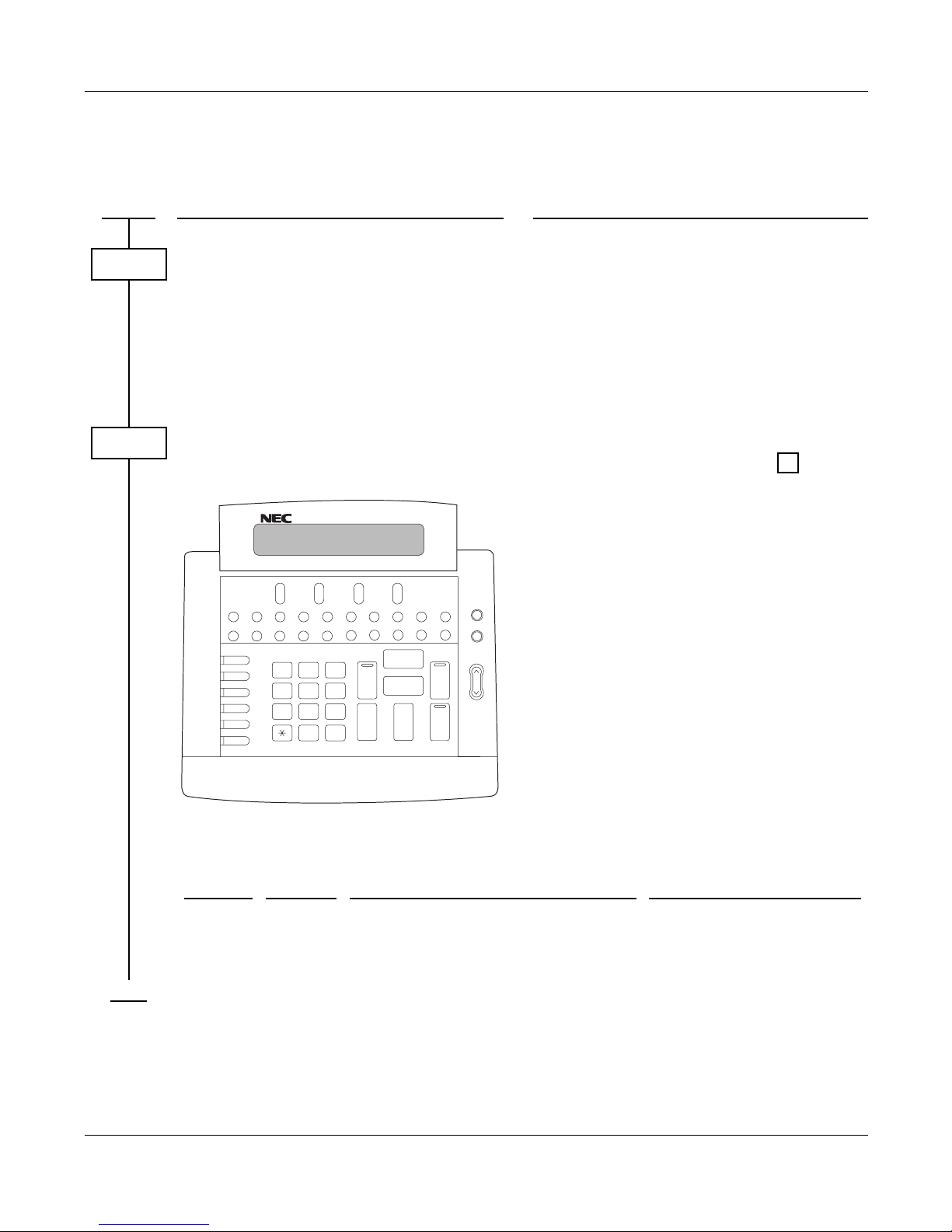
– 55 – NWA-008845-001 Rev.5.0
32ch1001.fm
ATTENDANT CALL SELECTION
PROGRAMMING
DESCRIPTION DATA
Specify the ATT call Selection key to which incoming calls from each trunk route terminate.
•
(1)
(2)
Y=15
00-15: Trunk Route No.
ATT Call Selection Key:
00-07: C.O. Incoming Call 0-7
10-17: FX Incoming Call 0-7
20-27: WATS Incoming Call 0-7
30-37: CCSA Incoming Call 0-7
40-47: Tie Line Incoming Call 0-7
Assign the ATT Call Selection Keys required
according to the key label.
•
(1)
(2)
Y=00
ATTCON No. (E000-E007) + + Key
No.
F60XX
XX: 00-07 (C.O. Incoming Call 0-7)
10-17 (FX Incoming Call 0-7)
20-27 (WATS Incoming Call 0-7)
30-37 (CCSA Incoming Call 0-7)
40-47 (Tie Line Incoming Call 0-7)
50-53 (Special Operator Call 0-3)
54 (Priority Call 0)
55 (Priority Call 1)
56 (Emergency Call)
60 (Operator Call)
61 (Recall)
62 (Serial Call)
63 (Call Forwarding-No Answer)
64 (Call Forwarding-Busy Line)
65 (Call Forwarding-Intercept)
66 (Off Hook Alarm)
67 (Interposition Calling/Transfer)
START
CM35
CM90
L6 (12)
L5 (11)
L4 (10)
L3 (09)
L2 (08)
L1 (07)
0
89
6
3
5
2
1
4
7
#
SRC
(90)
DEST
(91)
(93)
(95)
Answer
(96)
Hold
(94)
Release
(97)
Cancel
Talk
Position Busy
Volume
Night
(15)
(01) (02) (03)
(04)
(13) (16) (17) (18) (92) (19) (20) (21)(14)
(24)(22)
(23)
LDN TIE Busy ATND NANS Recall
EMG BV TRKSL Call Park SC SVC
REC
Mute
PAGE
Start
,
Key No. Data Description (Key Label) Default Data
13
16
18
F6000
F6060
F6061
C.O. Incoming 0 (LDN)
Operator Call (ATND)
Recall (Recall)
NONE
F6061 (Recall)
F6000 (C.O. Incoming 0)
END
ATTENDANT CONSOLE
ATTENDANT CALL SELECTION
Page 74

– 56 – NWA-008845-001 Rev.5.0
32ch1001.fm
ATTENDANT DO NOT DISTURB SETUP AND CANCEL
PROGRAMMING
DESCRIPTION DATA
Assign Do Not Disturb-System to the required
stations.
•
(1)
(2)
Y=00
X-XXXXXXXX: Station No.
0: To provide
Assign Do Not Disturb and Do Not Disturb
Override function keys to each DESKCON, if
needed.
NOTE: By resident system program, the
Multi-Function keys are programmed to provide a Do Not
Disturb Override key when the
attendant calls a station in Do Not
Disturb.
•
(1)
(2)
Y=00
ATTCON No. (E000-E007) + + Key
No.
F6102: Do Not Disturb
F6108: Do Not Disturb Override
F6104: Reset
START
CM13
CM90
,
END
ATTENDANT CONSOLE
ATTENDANT DO NOT DISTURB SETUP AND CANCEL
Page 75
– 57 – NWA-008845-001 Rev.5.0
32ch1001.fm
ATTENDANT INTERPOSITION CALLING/TRANSFER
PROGRAMMING
DESCRIPTION DATA
Assign the access code for Interposition Transfer.
•
(1)
(2)
Y=0-3 Numbering Plan Group 0-3
X-XXXX: Access Code
A095
Assign the Attendant Call Selection Key for
this feature on the DESKCON.
•
(1)
(2)
Y=00
ATTCON No. (E000-E007) + + Key
No.
F6067: Attendant Interposition Calling/
Transfer (Transferred ATTENDANT CONSOLE Answer key/
lamp)
Specify the Inter-Position Transferred call to
another tenant’s Attendant Console.
If the data is set to 1, a call from any station can
be transferred to another Attendant Console
regardless of Tenant Allocation by CM62.
(1)
(2)
143
0 : Restricted
1 : Allowed
START
CM20
CM90
,
CM08
END
NOVEMBER/15/2006
ATTENDANT CONSOLE
ATTENDANT INTERPOSITION CALLING/TRANSFER
Page 76
– 58 – NWA-008845-001 Rev.5.0
32ch1001.fm
ATTENDANT LISTED DIRECTORY NUMBER
PROGRAMMING
DESCRIPTION DATA
Provide the system with diversion display. (1)
(2)
204
0: Available
Specify the Incoming Call Identification (ICI)
key to which each LDN call or Tie Line call
from each trunk route will terminate.
•
(1)
(2)
Y=15
00-63: Trunk Route No.
00-07: C.O. Incoming Call 0-7
40-47: Tie Line Incoming Call 0-7
Assign the required number of ICI key on the
DESKCON.
•
(1)
(2)
Y=00
ATTCON No. + + Key No.
F60XX
F6000-F6007: C.O. Incoming Call 0-7
F6040-F6047: Tie Line Incoming Call 0-7
Assign the indialed number to each LDN key
or Tie Line key assigned by CM90.
The indialed number should be different from
any numbers assigned by CM10/CM14 and
CM11.
•
(1)
(2)
Y=01 For DID
0 : Effective data in CM35 Y=15
1-8: LDN Key 0-7 assigned by CM90
X-XXXX: Indialed No.
•
(1)
(2)
Y=02 For Tie Line
0 : Effective data in CM35 Y=15
1-8: Tie Line Key 0-7 assigned by CM90
X-XXXX: Indialed No.
START
CM08
CM35
CM90
,
CM50
END
ATTENDANT CONSOLE
ATTENDANT LISTED DIRECTORY NUMBER
Page 77

– 59 – NWA-008845-001 Rev.5.0
32ch1001.fm
To provide the LDN Diversion feature, the following programming is also required.
DESCRIPTION DATA
Provide the system with the LDN Diversion
feature.
(1)
(2)
205
0: Available
Assign the data for LDN Diversion to each
indialed number assigned by CM50 Y=01/02.
NOTE: A call is diverted to LDN0-7/TIE0-7
keys as specified by CM58 Y=02-07,
even if CM50 Y=01/02>1-8 has
been set.
•
(1)
(2)
Y=00 Tenant No. of LDN
00 : Effective data in CM35 Y=15
01-08: LDN Key 0-7 assigned by CM50
Y=01
10 : Effective data in CM35 Y=15
11-18: Tie Line Key 0-7 assigned by CM50
Y=02
00-63: Tenant No.
•
(1)
(2)
Y=01 TAS Group No.
Same as CM58 Y=00
00-63: TAS Group No. assigned by
CM44>13
•
(1)
(2)
Y=02 Day Mode Destination of LDN
Same as CM58 Y=00
00-07: LDN/TIE key 0-7
08 : To TAS
09 : To the station/outside party assigned
by CM58 Y=08
•
(1)
(2)
Y=03 Night Mode Destination of LDN
Same as CM58 Y=00
00-07: LDN/TIE key 0-7
08 : To TAS
09 : To the station/outside party assigned
by CM58 Y=09
•
(1)
(2)
Y=04 Day Mode diversion for busy
destination station
Same as CM58 Y=00
00: To Attendant Console (BUSY key)
08: To TAS
09: Camped on
START
CM08
CM58
A
ATTENDANT CONSOLE
ATTENDANT LISTED DIRECTORY NUMBER
Page 78

– 60 – NWA-008845-001 Rev.5.0
32ch1001.fm
HARDWARE REQUIRED
DIT card (DID Trunk)
ODT card (Tie Line Trunk)
DESCRIPTION DATA
•
(1)
(2)
Y=05 Night Mode diversion for busy
destination station
Same as CM58 Y=00
Same as CM58 Y=04
•
(1)
(2)
Y=06 Day Mode diversion for nonanswering destination station
Same as CM58 Y=00
00: To Attendant Console (NANS key)
08: To TAS
•
(1)
(2)
Y=07 Night Mode diversion for nonanswering destination station
Same as CM58 Y=00
Same as CM58 Y=06
If a station is designated by CM58 Y=02, 03,
assign the station number or abbreviated code
for outside party to which the call is to be
diverted.
•
(1)
(2)
Y=08 Day Mode station number
Same as CM58 Y=00
X-XXXXXXXX: Station No.
CXX : Abbreviated code for
outside party
XX: 00-31 given by
CM71>66
•
(1)
(2)
Y=09 Night Mode station number
Same as CM58 Y=00
Same as CM58 Y=08
A
CM58
END
ATTENDANT CONSOLE
ATTENDANT LISTED DIRECTORY NUMBER
Page 79

– 61 – NWA-008845-001 Rev.5.0
32ch1001.fm
ATTENDANT LOOP RELEASE
PROGRAMMING
To reenter the call that has been released from a loop before Automatic Recall:
DESCRIPTION DATA
Provide the system with the Attendant Loop
Release feature.
(1)
(2)
014: Attendant Loop Release
0: Available
DESCRIPTION DATA
Assign the access code for Call Pickup-Direct. •
(1)
(2)
Y=0-3 Numbering Plan Group 0-3
X-XXXX: Access Code
A021: Call Pickup-Direct
START
CM08
END
START
CM20
END
ATTENDANT CONSOLE
ATTENDANT LOOP RELEASE
Page 80
– 62 – NWA-008845-001 Rev.5.0
32ch1001.fm
ATTENDANT PROGRAMMING
PROGRAMMING
DESCRIPTION DATA
Assign the password for Attendant
Programming.
•
(1)
(2)
Y=30
0
X-X...X: Password (Maximum 8 digits)
X : 0-9, A (*), B (#)
If no data is set, the default setting is NONE.
In this case, the password is set to “12345678”.
Assign the program key for providing Attendant Programming on the DESKCON.
•
(1)
(2)
Y=00
ATTCON No. (E000-E007) + + Key
No.
F6111
Assign the access code for providing Attendant Programming for the DESKCON, if required.
•
(1)
(2)
Y=0-3 Numbering Plan Group 0-3
X-XXXX: Access Code
A156
START
CM60
CM90
,
CM20
END
ATTENDANT CONSOLE
ATTENDANT PROGRAMMING
Page 81

– 63 – NWA-008845-001 Rev.5.0
32ch1001.fm
CALL QUEUING
PROGRAMMING
Refer to CALL WAITING DISPLAY. Page 65
ATTENDANT CONSOLE
CALL QUEUING
Page 82
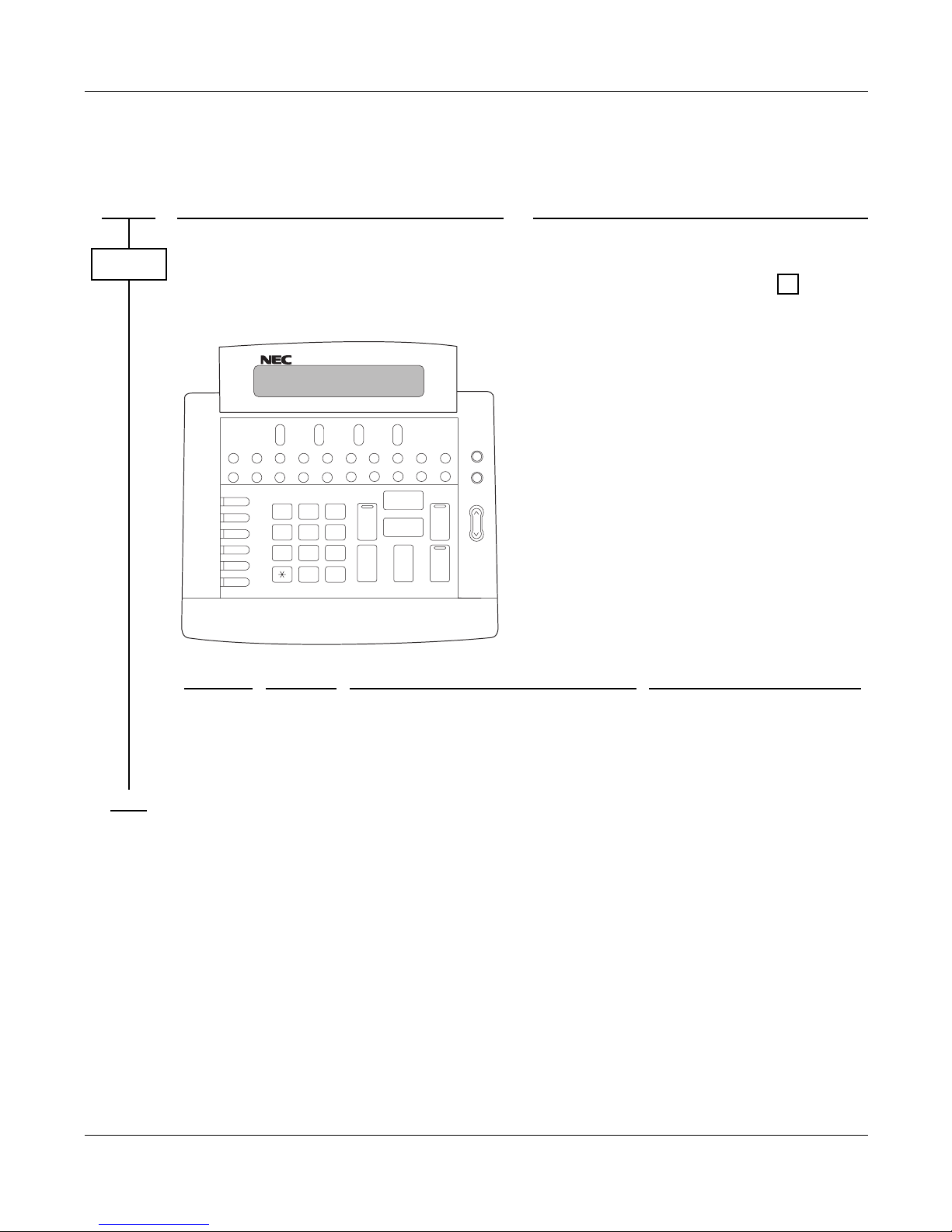
– 64 – NWA-008845-001 Rev.5.0
32ch1001.fm
CALL SPLITTING
PROGRAMMING
DESCRIPTION DATA
Assign the SRC, DEST, TALK, and CANCEL
keys on the DESKCON according to the key
label.
•
(1)
(2)
Y=00
ATTCON No. (E000-E007) + + Key
No.
F6200: SRC
F6201: DEST
F6202: CANCEL
F6203: TALK
START
CM90
L6 (12)
L5 (11)
L4 (10)
L3 (09)
L2 (08)
L1 (07)
0
89
6
3
5
2
1
4
7
#
SRC
(90)
DEST
(91)
(93)
(95)
Answer
(96)
Hold
(94)
Release
(97)
Cancel
Talk
Position Busy
Volume
Night
(15)
(01) (02) (03)
(04)
(13) (16) (17) (18) (92) (19) (20) (21)(14)
(24)(22)
(23)
LDN TIE Busy ATND NANS Recall
EMG BV TRKSL Call Park SC SVC
REC
Mute
PAGE
Start
,
Key No. Data Description (Key Label) Default Data
90
91
93
95
F6200
F6201
F6203
F6202
Source (SRC)
Destination (DEST)
Talk (Talk )
Cancel (Cancel)
F6200 (Source)
F6201 (Destination)
NONE
F6202 (Cancel)
END
ATTENDANT CONSOLE
CALL SPLITTING
Page 83

– 65 – NWA-008845-001 Rev.5.0
32ch1001.fm
CALL WAITING DISPLAY
PROGRAMMING
DESCRIPTION DATA
Specify the number of waiting calls which
cause the Call Waiting lamp to flash.
(1)
(2)0001-48 : 1 call-48 calls
NONE : 6 calls
START
CM42
END
ATTENDANT CONSOLE
CALL WAITING DISPLAY
Page 84

– 66 – NWA-008845-001 Rev.5.0
32ch1001.fm
COMMON ROUTE INDIAL
PROGRAMMING
DESCRIPTION DATA
Provide the system with Diversion Display. (1)
(2)
204
0: Available
Assign the required number of LDN keys on
the DESKCON.
•
(1)
(2)
Y=00
ATTCON No. (E000-E007) + + Key
No.
F6000-F6007: LDN0-7
Assign the indialed number to each LDN key
assigned by CM90. The indialed number
should be different from any numbers assigned
by CM10/CM14 and CM11.
•
(1)
(2)
Y=01
1-8: LDN key 0-7 assigned by CM90
X-XXXX: Indialed No.
Assign the destination to which a DID call is
transferred when an unassigned number is dialed.
•
(1)
(2)
Y=06 For DID Call
00-63: Tenant No.
X-XXXXXXXX: Station No.
E000 : Attendant Console
START
CM08
CM90
,
CM50
CM51
END
ATTENDANT CONSOLE
COMMON ROUTE INDIAL
Page 85

– 67 – NWA-008845-001 Rev.5.0
32ch1001.fm
To provide the LDN Diversion feature, the following programming is also required.
DESCRIPTION DATA
Provide the system with the LDN Diversion
feature.
(1)
(2)
205
0: Available
Assign the data for LDN Diversion to each
indialed number assigned by CM50 Y=01.
•
(1)
(2)
Y=00 Tenant No. of LDN
01-08: LDN0-7 assigned by CM50 Y=01
00-63: Tenant No.
•
(1)
(2)
Y=01 TAS Group No.
Same as CM58 Y=00
00-63: TAS Group No.
NOTE: A call is diverted to LDN0-7 keys as
specified by CM58 Y=02-07, even if
CM50 Y=01>1-8 has been set.
•
(1)
(2)
Y=02 Day Mode destination of LDN
Same as CM58 Y=00
00-07: LDN0-7 key
08 : To TAS
09 : To the station/outside party assigned
by CM58 Y=08
•
(1)
(2)
Y=03 Night Mode destination of LDN
Same as CM58 Y=00
00-07: LDN0-7 key
08 : To TAS
09 : To the station/outside party assigned
by CM58 Y=09
•
(1)
(2)
Y=04 Day Mode diversion for busy destination station
Same as CM58 Y=00
00: To Attendant Console (BUSY key)
08: To TAS
09: Camped on
START
CM08
CM58
A
ATTENDANT CONSOLE
COMMON ROUTE INDIAL
Page 86

– 68 – NWA-008845-001 Rev.5.0
32ch1001.fm
HARDWARE REQUIRED
DIT card (DID Trunk)
DESCRIPTION DATA
•
(1)
(2)
Y=05 Night Mode diversion for busy
destination station
Same as CM58 Y=00
Same as CM58 Y=04
•
(1)
(2)
Y=06 Day Mode diversion for nonanswering destination station
Same as CM58 Y=00
00: To Attendant Console (NANS key)
08: To TAS
•
(1)
(2)
Y=07 Night Mode diversion for nonanswering destination station
Same as CM58 Y=00
Same as CM58 Y=06
If a station is designated by CM58 Y=02, 03,
assign the station number to which the call is to
be diverted.
•
(1)
(2)
Y=08 Day Mode destination station
Same as CM58 Y=00
X-XXXXXXXX: Station No.
•
(1)
(2)
Y=09 Night Mode destination station
Same as CM58 Y=00
Same as CM58 Y=08
A
CM58
END
ATTENDANT CONSOLE
COMMON ROUTE INDIAL
Page 87
– 69 – NWA-008845-001 Rev.5.0
32ch1001.fm
DIALED NUMBER IDENTIFICATION SERVICE (DNIS)
PROGRAMMING
DESCRIPTION DATA
Provide the system with Diversion Display. (1)
(2)
204
0: Available
Specify the Incoming Call Identification (ICI)
key to which each LDN call or Tie Line call
from each trunk route will terminate.
•
(1)
(2)
Y=15
00-63: Trunk Route No.
00-07: C.O. Incoming Call 0-7
40-47: Tie Line Incoming Call 0-7
Assign the required number of LDN keys on
the DESKCON.
•
(1)
(2)
Y=00
ATTCON No. (E000-E007) + + Key
No.
F6000-F6007: C.O. Incoming Call 0-7
F6040-F6047: Tie Line Incoming Call 0-7
Assign the indialed number to each LDN key
or Tie Line key assigned by CM90. The
indialed number should be different from any
numbers assigned by CM10/CM14 and CM11.
•
(1)
(2)
Y=01 For DID
0 : Effective data in CM35 Y=15
1-8: LDN key 0-7 assigned by CM90
X-XXXX: Indialed No.
•
(1)
(2)
Y=02 For Tie Line
0 : Effective data in CM35 Y=15
1-8: Tie Line key 0-7 assigned by CM90
X-XXXX: Indialed No.
Tenant number of the LDN assigned by CM50
Y=01.
•
(1)
(2)
Y=00
00 : Effective data in CM35 Y=15
01-08: LDN Key 0-7 assigned by CM90
00-63: Tenant 00-63
START
CM08
CM35
CM90
,
CM50
CM58
END
ATTENDANT CONSOLE
DIALED NUMBER IDENTIFICATION SERVICE (DNIS)
Page 88

– 70 – NWA-008845-001 Rev.5.0
32ch1001.fm
To provide the LDN Diversion feature, the following programming is also required.
HARDWARE REQUIRED
DIT card (DID Trunk)
ODT card (Tie Line Trunk)
DESCRIPTION DATA
Provide the system with LDN Diversion
feature.
(1)
(2)
205
0: Available
Assign the data for LDN Diversion to each indialed number assigned by CM50 Y=01.
NOTE: A call is diverted to LDN 0-7 keys as
specified by CM58 Y=02, Y=03,
even if CM50 Y=01/02>1-8 has
been set.
•
(1)
(2)
Y=02 Day Mode Destination of LDN
00 : Effective data in CM35 Y=15
01-08: LDN key 0-7 assigned by CM90
10 : Effective data in CM35 Y=15
11-18: Tie Line key 0-7 assigned by CM90
00-07: LDN/TIE key 0-7
•
(1)
(2)
Y=03 Night Mode destination of LDN
Same as CM58 Y=02
00-07: LDN/TIE key 0-7
•
(1)
(2)
Y=08 Day Mode destination station
Same as CM58 Y=02
X-XXXXXXXX: Station No.
CXX : Abbreviated code for
outside party
XX: 00-31 given by
CM71>66
•
(1)
(2)
Y=09 Night Mode destination station
Same as CM58 Y=02
Same as CM58 Y=08
START
CM08
CM58
END
ATTENDANT CONSOLE
DIALED NUMBER IDENTIFICATION SERVICE (DNIS)
Page 89

– 71 – NWA-008845-001 Rev.5.0
32ch1001.fm
INCOMING CALL IDENTIFICATION
PROGRAMMING
Refer to the following.
SN716 DESKCON Page 47
ATTENDANT CALLED/CALLING NAME DISPLAY Page 51
ATTENDANT CALL SELECTION Page 55
ATTENDANT LISTED DIRECTORY NUMBER Page 58
COMMON ROUTE INDIAL Page 66
ATTENDANT CONSOLE
INCOMING CALL IDENTIFICATION
Page 90

– 72 – NWA-008845-001 Rev.5.0
32ch1001.fm
INDIVIDUAL TRUNK ACCESS
PROGRAMMING
DESCRIPTION DATA
Assign the access code for Individual Trunk
Access.
•
(1)
(2)
Y=0-3 Numbering Plan Group 0-3
X-XXXX: Access Code
A081
Assign the Trunk identification code to each
trunk.
The Trunk ID code is to be dialed after the
access code, and displayed on the Attendant
Console.
•
(1)
(2)
Y=19
000-255: Trunk No. assigned by CM10/
CM14 (D000-D255)
XXXX: Trunk ID code NOTE
Set any desired number (4 digit).
NOTE: By loading Resident System Pro-
gram, Trunk Identification Codes are
assigned as follows.
1XXX
XXX: 000-255: Trunk Number
START
CM20
CM30
END
ATTENDANT CONSOLE
INDIVIDUAL TRUNK ACCESS
Page 91
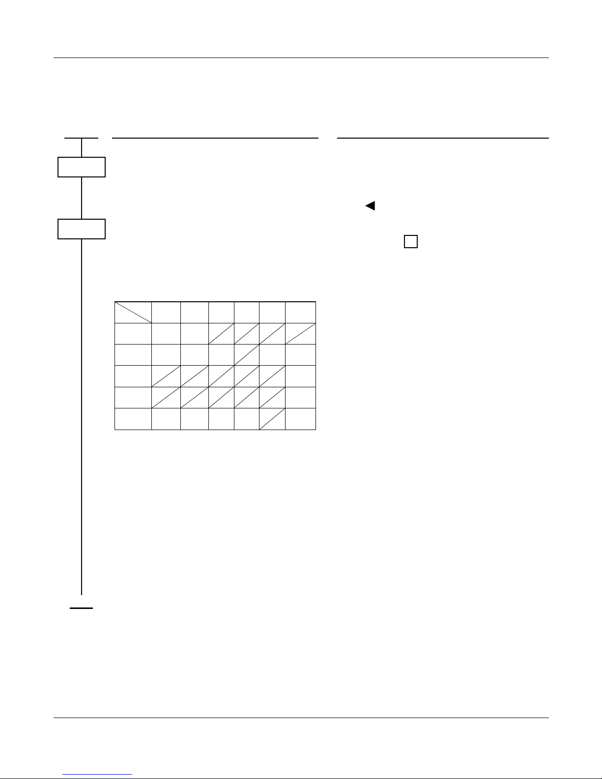
– 73 – NWA-008845-001 Rev.5.0
32ch1001.fm
MULTI-FUNCTION KEY
PROGRAMMING
DESCRIPTION DATA
Provide each DESKCON Multi-Function key
capability.
•
(1)
(2)
Y=17
0-7: ATTCON No. assigned by CM10/
CM14
1 : Effective
Assign the required Multi-Function keys to the
each DESKCON.
NOTE 1: The following data is assigned as
initial data or resident data.
NOTE 2: When setting or canceling a group
of stations in Do Not Disturb/Room
Cutoff, ATTCON Status number 00
should be used.
NOTE 3: For the SN716 DESKCON Multi-
Function key, do not assign the
MODE key (F6110).
NOTE 4: Key No. 05-06 is not available for
SN716 DESKCON.
•
(1)
(2)
Y=00
EXX Y + + Multi-Function key No.
(01-04: DESKCON)
XX: 00-04: ATTCON Status No.
00: Idle State NOTE 2
01: When answering or originating
02: When called station is busy
03: When called station is DND
04: When accessing Hotel feature
Y : 0-7: ATTCON No.
F6100: Room Cutoff
F6101: Message Waiting
F6102: Do Not Disturb
F6104: Reset
F6105: Serial Call Set
F6106: Flash over trunk
F6107: Busy Verification
F6108: Do Not Disturb Override
F6109: Wake Up
F6110: Mode NOTE 3
F6111: Programming
F6112: Out pulse (PB Signal) Short
F6113: Out pulse (PB Signal) Long
F6203: Talk
START
CM60
CM90
Key No.
ATTCON
Status No.
01 02 03 04 05 06
00
01
02
03
04
F6110
F6112
F6100
F6111
F6101
F6113 F6106
F6102 F6109
F6105 F6203
F6104
RESET
F6107
F6108
MODE PROG
SPB LPB SHF SC TALK
BV
DDOV
RC MW DD WW
,
END
ATTENDANT CONSOLE
MULTI-FUNCTION KEY
Page 92

– 74 – NWA-008845-001 Rev.5.0
32ch1001.fm
MULTIPLE CONSOLE OPERATION
PROGRAMMING
Refer to ATTENDANT CONSOLE (SN716 DESKCON). Page 47
ATTENDANT CONSOLE
MULTIPLE CONSOLE OPERATION
Page 93

– 75 – NWA-008845-001 Rev.5.0
32ch1001.fm
PUSHBUTTON CALLING-ATTENDANT ONLY
PROGRAMMING
DESCRIPTION DATA
Assign the type of signaling (DTMF) to
Outgoing and Bothway Trunk Routes.
•
(1)
(2)
Y=01
00-63: Trunk Route No.
7 : DP/DTMF (Incoming)
DTMF (Outgoing)
START
CM35
END
ATTENDANT CONSOLE
PUSHBUTTON CALLING-ATTENDANT ONLY
Page 94

– 76 – NWA-008845-001 Rev.5.0
32ch1001.fm
SERIAL CALL
PROGRAMMING
DESCRIPTION DATA
Assign the SERIAL CALL SET and SERIAL
CALL Keys on the DESKCON.
•
(1)
(2)
Y=00
ATTCON No. (E000-E007) + + Key
No.
F6062: Serial Call Termination
F6105: Serial Call Set
START
CM90
,
END
ATTENDANT CONSOLE
SERIAL CALL
Page 95
– 77 – NWA-008845-001 Rev.5.0
32ch1001.fm
TRUNK GROUP BUSY DISPLAY
PROGRAMMING
HARDWARE REQUIRED
To provide the Trunk Group Busy Lamps externally:
DK card and lamp indicator provided by customer
DESCRIPTION DATA
Assign the trunk group number to each trunk.
Several trunks may be assigned to one trunk
group number.
•
(1)
(2)
Y=09
000-255: Trunk No.
01-62: Trunk Group No.
For providing the Trunk Group Busy Lamps
on Attendant Console, assign the trunk group
number to required key.
NOTE 1: Maximum 6 keys per DESKCON
can be assigned. Any six trunk group
number out of trunk group number
01-62 can be assigned.
NOTE 2: Key number 1-6 should not be
assigned to provide a Trunk Group
Busy Lamp.
•
(1)
(2)
Y=00
ATTCON No. (E000-E007) + + Key
No.
F12XX
XX: 01-62: Trunk Group No. assigned by
CM30 Y=09
For providing external Trunk Group Busy
Lamps, assign the trunk group number to the
required circuit number on the DK card or
circuit number of the external relay control on
the MP card.
(1)
(2)
XX Y
XX: 00-31: DK Card No. E800-E831
assigned by CM10/CM14
Y : 0-3: Circuit No.
313: Built-in DK on MP card
11XX
XX: 01-62: Trunk Group No. assigned by
CM30 Y=09
START
CM30
CM90
,
CM44
END
ATTENDANT CONSOLE
TRUNK GROUP BUSY DISPLAY
Page 96

– 78 – NWA-008845-001 Rev.5.0
32ch1001.fm
UNSUPERVISED TRUNK-TO-TRUNK TRANSFER BY ATTENDANT
PROGRAMMING
NOTE: The trunk associated with at least one side of the call must be programmed for answer and/or
release signals to ensure the trunks do not lock up.
Refer to “TRUNK-TO-TRUNK CONNECTION” Page 716 for data to be assigned to
each trunk.
DESCRIPTION DATA
Provide the system with this feature. (1)
(2)
206
0 : Not available
1 : Available
START
CM08
END
JULY/01/2006
ATTENDANT CONSOLE
UNSUPERVISED TRUNK-TO-TRUNK TRANSFER BY ATTENDANT
Page 97
– 79 – NWA-008845-001 Rev.5.0
32ch1002.fm
ATTENDANT DELAY ANNOUNCEMENT
PROGRAMMING
DESCRIPTION DATA
Assign a Digital Announcement Trunk card
number to the required LEN.
NOTE 1: The Digital Announcement Trunk
card number must be assigned to the
first LEN (Level 0), the third LEN
(Level 2), the fifth LEN (Level 4) and
the seventh LEN (Level 6) of each
LT slot.
(1)
(2)
000-763: LEN
EB002-EB127: Digital Announcement
Trunk Card No.
For PIM0/1 : EB002-EB031
For PIM2/3 : EB032-EB063
For PIM4/5 : EB064-EB095
For PIM6/7 : EB096-EB127
NOTE 2: EB000 and EB001 are dedicated to
built-in Digital Announcement Trunk
of the MP card.
Assign a Digital Announcement Trunk card
number to the required LEN.
[Series 3200 R6.2 software required]
NOTE 1: The Digital Announcement Trunk
card number must be assigned to the
first LEN (Level 0), the third LEN
(Level 2), the fifth LEN (Level 4) and
the seventh LEN (Level 6) of each
LT slot.
(1)
(2)
XX ZZZ: LEN
XX : 00-59: FP No.
ZZZ: 000-127: Port No.
EB002-EB127: Digital Announcement
Trunk Card No.
For FP No. 00 : EB002-EB031
For FP No. 01 : EB032-EB063
For FP No. 02 : EB064-EB095
For FP No. 03 : EB096-EB127
NOTE 2: EB000 and EB001 are dedicated to
built-in Digital Announcement Trunk
of the MP card.
Allow the Announcement Service via Digital
Announcement Trunk on Attendant Delay
Announcement.
•
(1)
(2)
Y=74
00-63: Trunk Route No.
0: Allow
Assign the function of the Digital Announcement Trunk card.
•
(1)
(2)
Y=00
000-001: Built-in DAT on MP card
002-127: Digital Announcement Trunk
Card No. assigned by CM10/
CM14 (EB002-EB127)
0F XX: Attendant Delay Announcement
XX : 00-63 (Message No.)
•
(1)
(2)
Y=0A
00-63: Tenant No.
00-63: Message No. assigned by CM49
Y=00
START
CM10
CM14
CM35
CM49
A
ATTENDANT DELAY ANNOUNCEMENT
Page 98
– 80 – NWA-008845-001 Rev.5.0
32ch1002.fm
HARDWARE REQUIRED
DAT card or MP card (built-in DAT)
DESCRIPTION DATA
Specify the replay timer of the message
recorded in the Digital Announcement Trunk.
(1)
(2)
165
0 : Replay at an interval assigned by
CM41 Y=0>47
1 : Replay only once
To record, replay, and delete a message, assign
the Digital Announcement Trunk access
codes, respectively.
•
(1)
(2)
Y=0-3 Numbering Plan Group 0-3
X-XXXX: Access Code
A100: Record
A101: Replay
A102: Delete
Specify the unanswered timing of message
replay.
•
(1)
(2)
Y=0
16
01-30: 4-120 seconds
(4 second increments)
If no data is set, the default setting is 32-36 seconds.
Specify the Attendant Delay Announcement
connection timer.
•
(1)
(2)
Y=0
67
01-32: 4-128 seconds
(4 second increments)
If no data is set, the default setting is 8-12 seconds.
Specify the interval time of message replay. •
(1)
(2)
Y=0
47
01-30: 4-120 seconds
(4 second increments)
If no data is set, the default setting is 32-36 seconds.
A
CM08
CM20
CM41
END
ATTENDANT DELAY ANNOUNCEMENT
Page 99
– 81 – NWA-008845-001 Rev.5.0
32ch1002.fm
ATTENDANT OVERFLOW
PROGRAMMING
DESCRIPTION DATA
Provide the system with Attendant Overflow. (1)
(2)
067
0: Available
Assign the data for terminating system in Day/
Night Mode for each trunk.
•
(1)
(2)
Y=02 Day Mode
000-255: Trunk No.
14: Termination to Attendant Console
•
(1)
(2)
Y=03 Night Mode
000-255: Trunk No.
04: Direct-in Termination
•
(1)
(2)
Y=05 Night Station Assignment
000-255: Trunk No.
X-XXXXXXXX: Station No.
Specify the timing interval for Attendant Overflow.
•
(1)
(2)
Y=0
01
01-30: 4-120 seconds
(4 second increments)
If no data is set, the default setting is 32-36 seconds.
START
CM08
CM30
CM41
END
ATTENDANT OVERFLOW
Page 100
– 82 – NWA-008845-001 Rev.5.0
32ch1002.fm
To set a station or an outside party as the Attendant Overflow destination:
DESCRIPTION DATA
Provide Call Forwarding-All Calls on
Attendant Overflow.
•
(1)
(2)
Y=173
00-63: Trunk Route No.
0: Available
Assign the destination of Attendant Overflow,
to the incoming trunk tenant.
For an outside number, assign the Virtual Line
station number.
•
(1)
(2)
Y=31
00-63: Incoming Trunk Tenant No.
X-XXXXXXXX: Station No.
Virtual Line Station No.
assigned by CM11
Assign the Virtual Line station number to the
required Virtual LEN.
(1)
(2)
000-255: Virtual LEN
[Series 3300 software or before]
0000-1019: Virtual LEN
[Series 3400 software or later]
X-XXXXXXXX: Virtual Line Station No.
Assign Service Restriction Class A to the
Virtual Line station.
•
(1)
(2)
Y=02
X-XXXXXXXX: Virtual Line Station No.
assigned by CM11
XX ZZ
XX: 00-15 : Service Restriction Class A
Allow Call Forwarding-All Calls-Outside in
Service Restriction Class A assigned by CM12
Y=02.
•
(1)
(2)
Y=26
00-15: Service Restriction Class A as-
signed by CM12 Y=02
1 : Allow
Set Call Forwarding-All Calls-Outside to the
Virtual Line station number assigned by
CM11.
•
(1)
(2)
Y=00
X-XXXXXXXX: Virtual Line Station No.
assigned by CM11
Destination No.: X-XXXX + + YY...Y
X-XXXX: Outgoing Trunk/LCR Group
Access Code (1-4 digits)
: Separate Mark
YY...Y : Called No. (Maximum 26 dig-
its)
START
CM35
CM51
CM11
CM12
CM15
CME6
,
,
A
ATTENDANT OVERFLOW
 Loading...