

Page 1
SONOS 7500/5500
System Basics
Page 2

User’s Guide
System Basics Guide
Philips SONOS 7500
Philips SONOS 5500
Page 3

© 2002 Philips Electronics
North America Corporation
All rights are reserved.
Reproduction in whole or in
part is prohibited without the
prior written consent of the
copyright holder.
Publication number
M2424-30000-sb-02
Edition 6
Published November, 2002
Printed in U.S.A.
Warra nt y
The information contained in
this document is subject to
change without notice.
Philips Ultrasound makes no
warranty of any kind with
regard to this material,
including, but not limited to,
the implied warranties of
merchantability and fitness for
a particular purpose.
Philips Ultrasound shall not be
liable for errors contained
herein or for incidental or
consequential damages in
connection with the furn ishing,
performance, or use of this
material.
This product may contain remanufactured parts equivalent
to new in performance or have
had incidental use.
WARNING
Electrical Shock Hazard
Do not remove system covers.
To avoid electrical shock, use
only supplied power cords and
connect only to properly
grounded wall (wall/mains)
outlets.
Explosion Hazard
Do not operate the system in
the presence of flammable
anesthetics.
Safety Information
Before you use the Philips
ultrasound system, be sure to
read the Safety and Standards
Guide.
Pay special attention to the
“Warnings” and “Cautions.”
The warnings explain the
dangers of electrical shock and
explosion hazard, the safety of
ultrasound, applications,
guidelines for fetal use, and
guidelines for setting controls
that affect acoustic output and
accuracy of clinical
measurements.
The cautions explain potential
dangers to equipment.
Warning symbol used in the
Text:
WARNING
Caution symbol used in the
Text:
CAUTION
Warning Symbols used on
the System or its Probes:
!
Instruction manual symbol:
The product is marked with
this symbol when it is necessary for the user to refer to the
user’s guide.
Dangerous voltages symbol:
Indicates potential for electrical shock.
Monitor Radiation
The monitor used in this
system complies with the FDA
regulations that were
applicable at the date of
manufacture (21 CFR
Subcategory J).
Prescription Device
The United States Food and
Drug Administration requires
the following labeling
statement:
Caution - Federal Law restricts
this device to use by or on the
order of a physician.
Important
marking is for
0123
Council Directive
93/42/EEC.
This system complies with the
Medical Device Directive.
Authorized EU
Representative:
Philips Medizin Systeme
Boeblingen GmbH
Hewlett-Packard-Str. 2
71034 Boeblingen
Germany
Philips Ultrasound
3000 Minuteman Road
Andover, MA 01810-1099
(978) 687-1501
www.medical.philips.com
Page 4

Printing History
Edition
Publication Date Software Revision
Edition 1 June 1997 A.0
Edition 2 January 31, 1998 A.1
Edition 3 April 1999 B.0
Edition 4 June 2000 B.1
Edition 5 June 2002 C.0
Edition 6 November 2002 D.0
iv Revision D.0
Page 5

Revision D.0 v
ssn February 10, 1999 C:\WINNT\Profiles\dapowell\Desktop\D.0 Books\CD FILES SONOS
D.0\System Basics D.0\Frame Files\Front.fm add.2
Page 6

Preface
Preface
This guide describes the basic operation of the Philips SONOS 7500 and
SONOS 5500 ultrasound imaging systems.
What’s New In This Guide For D.0
The following major additions, deletions, and changes were made to this guide for
software revision D.0:
• This manual does not include information about Live 3D and BiPlane imaging
modes. For more information about them, see the Using 3-Dimensional and
BiPlane Imaging guide.
• Material about the SONOS 4500 system and about strip-chart recorders is
removed, since these are not supported by software revision D.0.
• The book’s organization is changed, to make it easier for readers to use it in
conjunction with the SONOS system’s Getting Started Audio CD.
• A new chapter is added, to summarize how to set up, perform, and record
ultrasound exams. (See Chapter 6.)
• Brief introductions are added to all chapters, to provide better context and
perspective, and to give readers handy pointers to each chapter’s contents.
• The last chapter (about ordering supplies and accessories) is removed, and
replaced by ordering information at the end of Chapter 1.
vi Revision D.0
Page 7

Preface
The SONOS D.0 Documentation Set
Use this guide in conjunction with the following books:
• Controls Reference—Provides a detailed description of all system controls.
• Safety and Standards Guide—Provides information on safety issues.
• Measurements and Calculations Reference—Provides information on
measurements and calculations that you can perform on your ultrasound system.
• Transducer Reference—Provides information on the operation, care, and cleaning
of transducers.
Additionally, several specialty guides and multimedia products describe SONOS
imaging applications and optional packages:
• Using Integrated Digital Interface (IDI)
• Using Stress Echocardiography
• Using 3-Dimensional and BiPlane Imaging
• Using Contrast Imaging
• Using Acoustic Quantification
• Using Acoustic Densitometry
• SONOS Live 3D Cardiac Echo: Features and Fundamentals (a CD guide to
Live-3D cardiac imaging)
• LVO and Contrast CK: A Practical Approach (a video guide to SONOS contrast
echocardiography detection techniques)
• Stress Audio CD (a spoken guide to performing SONOS stress echocardiography
studies)
Conventions Used in This Guide
The following conventions are used in this guide:
• Touch-panel and rotary control names appear in bold text. For example,
Acquire Loop.
• Function keys appear in a box. For example,
Revision D.0 vii
ssn February 10, 1999 C:\WINNT\Profiles\dapowell\Desktop\D.0 Books\CD FILES SONOS
D.0\System Basics D.0\Frame Files\Front.fm add.2
Enter
.
Page 8

Preface
viii Revision D.0
Page 9

Contents
1 The System
Main Components . . . . . . . . . . . . . . . . . . . . . . . . . . . . . . . . . . . . . . . . . . . . . . . . . . . . . . . . . 1-1
Control Panel . . . . . . . . . . . . . . . . . . . . . . . . . . . . . . . . . . . . . . . . . . . . . . . . . . . . . . . . . . . . . 1-2
Touch Panels. . . . . . . . . . . . . . . . . . . . . . . . . . . . . . . . . . . . . . . . . . . . . . . . . . . . . . . . . . . . . . 1-3
System Power . . . . . . . . . . . . . . . . . . . . . . . . . . . . . . . . . . . . . . . . . . . . . . . . . . . . . . . . . . . . . 1-5
Systems without PCs . . . . . . . . . . . . . . . . . . . . . . . . . . . . . . . . . . . . . . . . . . . . . . . . . . . 1-5
Systems with PCs . . . . . . . . . . . . . . . . . . . . . . . . . . . . . . . . . . . . . . . . . . . . . . . . . . . . . . 1-5
Setting Up the System. . . . . . . . . . . . . . . . . . . . . . . . . . . . . . . . . . . . . . . . . . . . . . . . . . . . . . . 1-7
Entering Your Institution Name . . . . . . . . . . . . . . . . . . . . . . . . . . . . . . . . . . . . . . . . . . . 1-8
Setting the Date . . . . . . . . . . . . . . . . . . . . . . . . . . . . . . . . . . . . . . . . . . . . . . . . . . . . . . . .1-9
Setting the Time . . . . . . . . . . . . . . . . . . . . . . . . . . . . . . . . . . . . . . . . . . . . . . . . . . . . . . 1-10
Adjusting the Control Panel and Touch Panel Lighting . . . . . . . . . . . . . . . . . . . . . . . 1-11
Adjusting the Monitor Position . . . . . . . . . . . . . . . . . . . . . . . . . . . . . . . . . . . . . . . . . . 1-12
Calibrating the Monitor . . . . . . . . . . . . . . . . . . . . . . . . . . . . . . . . . . . . . . . . . . . . . . . . 1-13
Calibrating monitors with brightness/contrast dials on the front . . . . . . . . . . 1-13
Calibrating monitors with brightness/contrast push buttons on the front . . . . 1-14
Using the Foot Switch. . . . . . . . . . . . . . . . . . . . . . . . . . . . . . . . . . . . . . . . . . . . . . . . . . . . . .1-16
Supplies and Accessories . . . . . . . . . . . . . . . . . . . . . . . . . . . . . . . . . . . . . . . . . . . . . . . . . . . 1-17
Contents
vii, Revision D.0
ssn January 28, 1999 C:\WINNT\Profiles\dapowell\Desktop\D.0 Books\CD FILES SONOS D.0\System
Basics D.0\Frame Files\basicsTOC.fm add.1
Page 10

Contents
2 Transducers
Introduction . . . . . . . . . . . . . . . . . . . . . . . . . . . . . . . . . . . . . . . . . . . . . . . . . . . . . . . . . . . . . . . 2-1
Connecting Transducers . . . . . . . . . . . . . . . . . . . . . . . . . . . . . . . . . . . . . . . . . . . . . . . . . . . . .2-2
Imaging Transducers . . . . . . . . . . . . . . . . . . . . . . . . . . . . . . . . . . . . . . . . . . . . . . . . . . . .2-2
Nonimaging Doppler Pencil Transducers . . . . . . . . . . . . . . . . . . . . . . . . . . . . . . . . . . . .2-3
Activating Transducers . . . . . . . . . . . . . . . . . . . . . . . . . . . . . . . . . . . . . . . . . . . . . . . . . . . . . .2-4
Disconnecting and Storing Transducers . . . . . . . . . . . . . . . . . . . . . . . . . . . . . . . . . . . . . . . . . 2-5
Transducer Troubleshooting . . . . . . . . . . . . . . . . . . . . . . . . . . . . . . . . . . . . . . . . . . . . . . . . . . 2-6
3Presets
Introduction . . . . . . . . . . . . . . . . . . . . . . . . . . . . . . . . . . . . . . . . . . . . . . . . . . . . . . . . . . . . . . . 3-1
Philips-Defined Presets . . . . . . . . . . . . . . . . . . . . . . . . . . . . . . . . . . . . . . . . . . . . . . . . . . . . . . 3-2
Choosing Presets . . . . . . . . . . . . . . . . . . . . . . . . . . . . . . . . . . . . . . . . . . . . . . . . . . . . . . . . . . .3-3
Modifying Presets . . . . . . . . . . . . . . . . . . . . . . . . . . . . . . . . . . . . . . . . . . . . . . . . . . . . . . . . . . 3-4
Creating Presets. . . . . . . . . . . . . . . . . . . . . . . . . . . . . . . . . . . . . . . . . . . . . . . . . . . . . . . . . . . . 3-6
Storing Presets. . . . . . . . . . . . . . . . . . . . . . . . . . . . . . . . . . . . . . . . . . . . . . . . . . . . . . . . . . . . . 3-8
Copying Presets to a Different SONOS System . . . . . . . . . . . . . . . . . . . . . . . . . . . . . . . . . . .3-9
Deleting Presets. . . . . . . . . . . . . . . . . . . . . . . . . . . . . . . . . . . . . . . . . . . . . . . . . . . . . . . . . . . 3-10
viii, Revision D.0
Page 11

4 Peripheral Devices
Introduction. . . . . . . . . . . . . . . . . . . . . . . . . . . . . . . . . . . . . . . . . . . . . . . . . . . . . . . . . . . . . . . 4-1
System Monitor. . . . . . . . . . . . . . . . . . . . . . . . . . . . . . . . . . . . . . . . . . . . . . . . . . . . . . . . . . . . 4-2
Adjusting the Monitor Position . . . . . . . . . . . . . . . . . . . . . . . . . . . . . . . . . . . . . . . . . . . 4-2
Calibrating the Monitor . . . . . . . . . . . . . . . . . . . . . . . . . . . . . . . . . . . . . . . . . . . . . . . . . 4-2
Floppy Drive . . . . . . . . . . . . . . . . . . . . . . . . . . . . . . . . . . . . . . . . . . . . . . . . . . . . . . . . . . . . . . 4-3
Controls . . . . . . . . . . . . . . . . . . . . . . . . . . . . . . . . . . . . . . . . . . . . . . . . . . . . . . . . . . . . . 4-3
Accessing the Service Floppy Disk Drive . . . . . . . . . . . . . . . . . . . . . . . . . . . . . . . . . . . 4-4
Optical Disk Drive . . . . . . . . . . . . . . . . . . . . . . . . . . . . . . . . . . . . . . . . . . . . . . . . . . . . . . . . . 4-5
5 1/4-inch . . . . . . . . . . . . . . . . . . . . . . . . . . . . . . . . . . . . . . . . . . . . . . . . . . . . . . . . . . . . 4-5
3 1/2-inch . . . . . . . . . . . . . . . . . . . . . . . . . . . . . . . . . . . . . . . . . . . . . . . . . . . . . . . . . . . . 4-5
PC . . . . . . . . . . . . . . . . . . . . . . . . . . . . . . . . . . . . . . . . . . . . . . . . . . . . . . . . . . . . . . . . . . . . . . 4-6
VCR . . . . . . . . . . . . . . . . . . . . . . . . . . . . . . . . . . . . . . . . . . . . . . . . . . . . . . . . . . . . . . . . . . . . 4-6
Controls . . . . . . . . . . . . . . . . . . . . . . . . . . . . . . . . . . . . . . . . . . . . . . . . . . . . . . . . . . . . . 4-6
Primary . . . . . . . . . . . . . . . . . . . . . . . . . . . . . . . . . . . . . . . . . . . . . . . . . . . . . . . 4-6
Setup . . . . . . . . . . . . . . . . . . . . . . . . . . . . . . . . . . . . . . . . . . . . . . . . . . . . . . . . . 4-8
VCR Troubleshooting . . . . . . . . . . . . . . . . . . . . . . . . . . . . . . . . . . . . . . . . . . . . . . . . . . . 4-9
Printers . . . . . . . . . . . . . . . . . . . . . . . . . . . . . . . . . . . . . . . . . . . . . . . . . . . . . . . . . . . . . . . . . 4-10
Printing an Image Locally . . . . . . . . . . . . . . . . . . . . . . . . . . . . . . . . . . . . . . . . . . . . . . 4-10
DICOM Printers . . . . . . . . . . . . . . . . . . . . . . . . . . . . . . . . . . . . . . . . . . . . . . . . . . . . . . 4-12
Setting Up DICOM Print. . . . . . . . . . . . . . . . . . . . . . . . . . . . . . . . . . . . . . . . . 4-12
Using DICOM Prints. . . . . . . . . . . . . . . . . . . . . . . . . . . . . . . . . . . . . . . . . . . . 4-14
Acquiring Images . . . . . . . . . . . . . . . . . . . . . . . . . . . . . . . . . . . . . . . . . . . . . . 4-14
Retrieving Stored Images for DICOM Printing . . . . . . . . . . . . . . . . . . . . . . . 4-15
Selecting a Different Printer . . . . . . . . . . . . . . . . . . . . . . . . . . . . . . . . . . . . . . . . . . . . . 4-16
Printing an Analysis Report . . . . . . . . . . . . . . . . . . . . . . . . . . . . . . . . . . . . . . . . . . . . . 4-17
Printer Troubleshooting . . . . . . . . . . . . . . . . . . . . . . . . . . . . . . . . . . . . . . . . . . . . . . . . 4-18
Contents
ix, Revision D.0
ssn January 28, 1999 C:\WINNT\Profiles\dapowell\Desktop\D.0 Books\CD FILES SONOS D.0\System
Basics D.0\Frame Files\basicsTOC.fm add.1
Page 12

Contents
Configuring the RS-232 Interface. . . . . . . . . . . . . . . . . . . . . . . . . . . . . . . . . . . . . . . . . . . . . 4-20
Using the Remote Service Feature . . . . . . . . . . . . . . . . . . . . . . . . . . . . . . . . . . . . . . . . . . . .4-22
Connecting the Ultrasound System to a Modem . . . . . . . . . . . . . . . . . . . . . . . . . . . . . 4-23
Selecting Remote Service Mode . . . . . . . . . . . . . . . . . . . . . . . . . . . . . . . . . . . . . . . . . .4-24
Exiting Remote Service Mode . . . . . . . . . . . . . . . . . . . . . . . . . . . . . . . . . . . . . . . . . . .4-25
5Physios
Introduction . . . . . . . . . . . . . . . . . . . . . . . . . . . . . . . . . . . . . . . . . . . . . . . . . . . . . . . . . . . . . . . 5-1
Screen and Touch Panels. . . . . . . . . . . . . . . . . . . . . . . . . . . . . . . . . . . . . . . . . . . . . . . . . . . . .5-2
Controls . . . . . . . . . . . . . . . . . . . . . . . . . . . . . . . . . . . . . . . . . . . . . . . . . . . . . . . . . . . . . . . . . . 5-3
Primary . . . . . . . . . . . . . . . . . . . . . . . . . . . . . . . . . . . . . . . . . . . . . . . . . . . . . . . . . . . . . . 5-3
Setup . . . . . . . . . . . . . . . . . . . . . . . . . . . . . . . . . . . . . . . . . . . . . . . . . . . . . . . . . . . . . . . .5-6
Setting Up Physios . . . . . . . . . . . . . . . . . . . . . . . . . . . . . . . . . . . . . . . . . . . . . . . . . . . . . . . . .5-7
Setting Up Triggering Modes . . . . . . . . . . . . . . . . . . . . . . . . . . . . . . . . . . . . . . . . . . . . . . . . . 5-8
Connecting Physios. . . . . . . . . . . . . . . . . . . . . . . . . . . . . . . . . . . . . . . . . . . . . . . . . . . . . . . .5-10
Viewing Physios . . . . . . . . . . . . . . . . . . . . . . . . . . . . . . . . . . . . . . . . . . . . . . . . . . . . . . . . . .5-12
Physio Troubleshooting. . . . . . . . . . . . . . . . . . . . . . . . . . . . . . . . . . . . . . . . . . . . . . . . . . . . .5-14
x, Revision D.0
Page 13

6 Doing Exams
Introduction. . . . . . . . . . . . . . . . . . . . . . . . . . . . . . . . . . . . . . . . . . . . . . . . . . . . . . . . . . . . . . . 6-1
Selecting a Preset . . . . . . . . . . . . . . . . . . . . . . . . . . . . . . . . . . . . . . . . . . . . . . . . . . . . . . . . . . 6-1
Setting up the Exam . . . . . . . . . . . . . . . . . . . . . . . . . . . . . . . . . . . . . . . . . . . . . . . . . . . . . . . . 6-2
Connecting a Transducer . . . . . . . . . . . . . . . . . . . . . . . . . . . . . . . . . . . . . . . . . . . . . . . . . . . 6-10
Optimizing the Image . . . . . . . . . . . . . . . . . . . . . . . . . . . . . . . . . . . . . . . . . . . . . . . . . . . . . . 6-10
Videotaping the Exam . . . . . . . . . . . . . . . . . . . . . . . . . . . . . . . . . . . . . . . . . . . . . . . . . . . . . 6-11
Viewing Taped Images . . . . . . . . . . . . . . . . . . . . . . . . . . . . . . . . . . . . . . . . . . . . . . . . . 6-13
VCR Troubleshooting . . . . . . . . . . . . . . . . . . . . . . . . . . . . . . . . . . . . . . . . . . . . . . . . . . 6-14
Storing the Image . . . . . . . . . . . . . . . . . . . . . . . . . . . . . . . . . . . . . . . . . . . . . . . . . . . . . . . . . 6-15
Sending the Image Over a Network.. . . . . . . . . . . . . . . . . . . . . . . . . . . . . . . . . . . . . . . . . . . 6-15
7 Imaging Modalities
Contents
Introduction. . . . . . . . . . . . . . . . . . . . . . . . . . . . . . . . . . . . . . . . . . . . . . . . . . . . . . . . . . . . . . . 7-1
General Imaging Controls. . . . . . . . . . . . . . . . . . . . . . . . . . . . . . . . . . . . . . . . . . . . . . . . . . . . 7-2
Frequency Fusion Imaging . . . . . . . . . . . . . . . . . . . . . . . . . . . . . . . . . . . . . . . . . . . . . . . . . . . 7-4
Introduction . . . . . . . . . . . . . . . . . . . . . . . . . . . . . . . . . . . . . . . . . . . . . . . . . . . . . . . . . . . 7-4
Screen and Touch Panels . . . . . . . . . . . . . . . . . . . . . . . . . . . . . . . . . . . . . . . . . . . . . . . . 7-5
Icons . . . . . . . . . . . . . . . . . . . . . . . . . . . . . . . . . . . . . . . . . . . . . . . . . . . . . . . . . . . . . . . . 7-6
Controls . . . . . . . . . . . . . . . . . . . . . . . . . . . . . . . . . . . . . . . . . . . . . . . . . . . . . . . . . . . . . 7-6
Using Frequency Fusion . . . . . . . . . . . . . . . . . . . . . . . . . . . . . . . . . . . . . . . . . . . . . . . . . 7-7
xi, Revision D.0
ssn January 28, 1999 C:\WINNT\Profiles\dapowell\Desktop\D.0 Books\CD FILES SONOS D.0\System
Basics D.0\Frame Files\basicsTOC.fm add.1
Page 14

Contents
Harmonic Fusion Imaging. . . . . . . . . . . . . . . . . . . . . . . . . . . . . . . . . . . . . . . . . . . . . . . . . . . . 7-8
Introduction . . . . . . . . . . . . . . . . . . . . . . . . . . . . . . . . . . . . . . . . . . . . . . . . . . . . . . . . . . .7-8
Screen and Touch Panels . . . . . . . . . . . . . . . . . . . . . . . . . . . . . . . . . . . . . . . . . . . . . . . . 7-9
Icons . . . . . . . . . . . . . . . . . . . . . . . . . . . . . . . . . . . . . . . . . . . . . . . . . . . . . . . . . . . . . . . 7-10
Controls . . . . . . . . . . . . . . . . . . . . . . . . . . . . . . . . . . . . . . . . . . . . . . . . . . . . . . . . . . . . .7-12
Primary . . . . . . . . . . . . . . . . . . . . . . . . . . . . . . . . . . . . . . . . . . . . . . . . . . . . . .7-12
Secondary . . . . . . . . . . . . . . . . . . . . . . . . . . . . . . . . . . . . . . . . . . . . . . . . . . . .7-12
Using Harmonic Fusion . . . . . . . . . . . . . . . . . . . . . . . . . . . . . . . . . . . . . . . . . . . . . . . . 7-13
Zoom Mode. . . . . . . . . . . . . . . . . . . . . . . . . . . . . . . . . . . . . . . . . . . . . . . . . . . . . . . . . . . . . . 7-15
Introduction . . . . . . . . . . . . . . . . . . . . . . . . . . . . . . . . . . . . . . . . . . . . . . . . . . . . . . . . . .7-15
Screen and Touch Panels . . . . . . . . . . . . . . . . . . . . . . . . . . . . . . . . . . . . . . . . . . . . . . . 7-16
Controls . . . . . . . . . . . . . . . . . . . . . . . . . . . . . . . . . . . . . . . . . . . . . . . . . . . . . . . . . . . . .7-16
Using Zoom Mode . . . . . . . . . . . . . . . . . . . . . . . . . . . . . . . . . . . . . . . . . . . . . . . . . . . .7-17
Dual Imaging Mode . . . . . . . . . . . . . . . . . . . . . . . . . . . . . . . . . . . . . . . . . . . . . . . . . . . . . . .7-19
Introduction . . . . . . . . . . . . . . . . . . . . . . . . . . . . . . . . . . . . . . . . . . . . . . . . . . . . . . . . . .7-19
Screen and Touch Panels . . . . . . . . . . . . . . . . . . . . . . . . . . . . . . . . . . . . . . . . . . . . . . . 7-20
Controls . . . . . . . . . . . . . . . . . . . . . . . . . . . . . . . . . . . . . . . . . . . . . . . . . . . . . . . . . . . . .7-21
Using Dual Imaging Mode . . . . . . . . . . . . . . . . . . . . . . . . . . . . . . . . . . . . . . . . . . . . . . 7-21
Dual Imaging mode restrictions. . . . . . . . . . . . . . . . . . . . . . . . . . . . . . . . . . . . 7-22
2D Imaging . . . . . . . . . . . . . . . . . . . . . . . . . . . . . . . . . . . . . . . . . . . . . . . . . . . . . . . . . . . . . .7-23
Introduction . . . . . . . . . . . . . . . . . . . . . . . . . . . . . . . . . . . . . . . . . . . . . . . . . . . . . . . . . .7-23
Screen and Touch Panels . . . . . . . . . . . . . . . . . . . . . . . . . . . . . . . . . . . . . . . . . . . . . . . 7-24
Controls . . . . . . . . . . . . . . . . . . . . . . . . . . . . . . . . . . . . . . . . . . . . . . . . . . . . . . . . . . . . .7-25
Primary . . . . . . . . . . . . . . . . . . . . . . . . . . . . . . . . . . . . . . . . . . . . . . . . . . . . . .7-25
Secondary . . . . . . . . . . . . . . . . . . . . . . . . . . . . . . . . . . . . . . . . . . . . . . . . . . . .7-28
Setup . . . . . . . . . . . . . . . . . . . . . . . . . . . . . . . . . . . . . . . . . . . . . . . . . . . . . . . .7-29
xii, Revision D.0
Page 15

Contents
2D/BMode Imaging . . . . . . . . . . . . . . . . . . . . . . . . . . . . . . . . . . . . . . . . . . . . . . . . . . . . . . . 7-30
Introduction . . . . . . . . . . . . . . . . . . . . . . . . . . . . . . . . . . . . . . . . . . . . . . . . . . . . . . . . . .7-30
Screen and Touch Panels . . . . . . . . . . . . . . . . . . . . . . . . . . . . . . . . . . . . . . . . . . . . . . . 7-31
Controls . . . . . . . . . . . . . . . . . . . . . . . . . . . . . . . . . . . . . . . . . . . . . . . . . . . . . . . . . . . .7-32
Primary . . . . . . . . . . . . . . . . . . . . . . . . . . . . . . . . . . . . . . . . . . . . . . . . . . . . . . 7-32
Secondary . . . . . . . . . . . . . . . . . . . . . . . . . . . . . . . . . . . . . . . . . . . . . . . . . . . . 7-34
Setup . . . . . . . . . . . . . . . . . . . . . . . . . . . . . . . . . . . . . . . . . . . . . . . . . . . . . . . . 7-35
Using 2D/BMode . . . . . . . . . . . . . . . . . . . . . . . . . . . . . . . . . . . . . . . . . . . . . . . . . . . . . 7-36
Displaying a time gain compensation (TGC) curve . . . . . . . . . . . . . . . . . . . . 7-38
Biopsy Support . . . . . . . . . . . . . . . . . . . . . . . . . . . . . . . . . . . . . . . . . . . . . . . . . . . . . . . 7-39
Introduction . . . . . . . . . . . . . . . . . . . . . . . . . . . . . . . . . . . . . . . . . . . . . . . . . . . 7-39
Biopsy screens. . . . . . . . . . . . . . . . . . . . . . . . . . . . . . . . . . . . . . . . . . . . . . . . . 7-40
Controls . . . . . . . . . . . . . . . . . . . . . . . . . . . . . . . . . . . . . . . . . . . . . . . . . . . . . . 7-43
Probes supporting biopsy . . . . . . . . . . . . . . . . . . . . . . . . . . . . . . . . . . . . . . . . 7-44
2D/BMode Troubleshooting . . . . . . . . . . . . . . . . . . . . . . . . . . . . . . . . . . . . . . . . . . . . . 7-45
MMode Imaging . . . . . . . . . . . . . . . . . . . . . . . . . . . . . . . . . . . . . . . . . . . . . . . . . . . . . . . . . .7-48
Introduction . . . . . . . . . . . . . . . . . . . . . . . . . . . . . . . . . . . . . . . . . . . . . . . . . . . . . . . . . .7-48
Screen and Touch Panels . . . . . . . . . . . . . . . . . . . . . . . . . . . . . . . . . . . . . . . . . . . . . . . 7-49
Cardiac . . . . . . . . . . . . . . . . . . . . . . . . . . . . . . . . . . . . . . . . . . . . . . . . . . . . . . 7-49
Noncardiac . . . . . . . . . . . . . . . . . . . . . . . . . . . . . . . . . . . . . . . . . . . . . . . . . . . 7-50
Controls . . . . . . . . . . . . . . . . . . . . . . . . . . . . . . . . . . . . . . . . . . . . . . . . . . . . . . . . . . . .7-51
Cardiac . . . . . . . . . . . . . . . . . . . . . . . . . . . . . . . . . . . . . . . . . . . . . . . . . . . . . . 7-51
Noncardiac . . . . . . . . . . . . . . . . . . . . . . . . . . . . . . . . . . . . . . . . . . . . . . . . . . . 7-52
Using MMode . . . . . . . . . . . . . . . . . . . . . . . . . . . . . . . . . . . . . . . . . . . . . . . . . . . . . . . . 7-54
Displaying spectral and MMode traces. . . . . . . . . . . . . . . . . . . . . . . . . . . . . . 7-57
Displaying side-by-side MMode or Doppler . . . . . . . . . . . . . . . . . . . . . . . . . 7-58
Changing the display to full screen. . . . . . . . . . . . . . . . . . . . . . . . . . . . . . . . . 7-58
MMode Troubleshooting . . . . . . . . . . . . . . . . . . . . . . . . . . . . . . . . . . . . . . . . . . . . . . . 7-59
xiii, Revision D.0
ssn January 28, 1999 C:\WINNT\Profiles\dapowell\Desktop\D.0 Books\CD FILES SONOS D.0\System
Basics D.0\Frame Files\basicsTOC.fm add.1
Page 16

Contents
Color Imaging . . . . . . . . . . . . . . . . . . . . . . . . . . . . . . . . . . . . . . . . . . . . . . . . . . . . . . . . . . . . 7-60
Introduction . . . . . . . . . . . . . . . . . . . . . . . . . . . . . . . . . . . . . . . . . . . . . . . . . . . . . . . . . .7-60
Screen and Touch Panels . . . . . . . . . . . . . . . . . . . . . . . . . . . . . . . . . . . . . . . . . . . . . . . 7-61
Cardiac. . . . . . . . . . . . . . . . . . . . . . . . . . . . . . . . . . . . . . . . . . . . . . . . . . . . . . .7-61
Noncardiac. . . . . . . . . . . . . . . . . . . . . . . . . . . . . . . . . . . . . . . . . . . . . . . . . . . . 7-62
Controls . . . . . . . . . . . . . . . . . . . . . . . . . . . . . . . . . . . . . . . . . . . . . . . . . . . . . . . . . . . . .7-63
Cardiac primary . . . . . . . . . . . . . . . . . . . . . . . . . . . . . . . . . . . . . . . . . . . . . . . . 7-63
Cardiac secondary . . . . . . . . . . . . . . . . . . . . . . . . . . . . . . . . . . . . . . . . . . . . . . 7-65
Noncardiac primary . . . . . . . . . . . . . . . . . . . . . . . . . . . . . . . . . . . . . . . . . . . . . 7-66
Noncardiac secondary . . . . . . . . . . . . . . . . . . . . . . . . . . . . . . . . . . . . . . . . . . . 7-68
Setup . . . . . . . . . . . . . . . . . . . . . . . . . . . . . . . . . . . . . . . . . . . . . . . . . . . . . . . .7-69
Using Color Imaging . . . . . . . . . . . . . . . . . . . . . . . . . . . . . . . . . . . . . . . . . . . . . . . . . . . 7-70
Adaptive Flow . . . . . . . . . . . . . . . . . . . . . . . . . . . . . . . . . . . . . . . . . . . . . . . . .7-72
Color Compare. . . . . . . . . . . . . . . . . . . . . . . . . . . . . . . . . . . . . . . . . . . . . . . . .7-73
Color Troubleshooting . . . . . . . . . . . . . . . . . . . . . . . . . . . . . . . . . . . . . . . . . . . . . . . . .7-75
PW and CW Imaging . . . . . . . . . . . . . . . . . . . . . . . . . . . . . . . . . . . . . . . . . . . . . . . . . . . . . . 7-79
Introduction . . . . . . . . . . . . . . . . . . . . . . . . . . . . . . . . . . . . . . . . . . . . . . . . . . . . . . . . . .7-79
Screen and Touch Panels . . . . . . . . . . . . . . . . . . . . . . . . . . . . . . . . . . . . . . . . . . . . . . . 7-80
Cardiac. . . . . . . . . . . . . . . . . . . . . . . . . . . . . . . . . . . . . . . . . . . . . . . . . . . . . . .7-80
PW Spectral (Noncardiac) . . . . . . . . . . . . . . . . . . . . . . . . . . . . . . . . . . . . . . . . 7-81
Controls . . . . . . . . . . . . . . . . . . . . . . . . . . . . . . . . . . . . . . . . . . . . . . . . . . . . . . . . . . . . .7-82
Cardiac primary . . . . . . . . . . . . . . . . . . . . . . . . . . . . . . . . . . . . . . . . . . . . . . . . 7-82
Cardiac secondary . . . . . . . . . . . . . . . . . . . . . . . . . . . . . . . . . . . . . . . . . . . . . . 7-84
Cardiac setup . . . . . . . . . . . . . . . . . . . . . . . . . . . . . . . . . . . . . . . . . . . . . . . . . .7-85
Noncardiac primary . . . . . . . . . . . . . . . . . . . . . . . . . . . . . . . . . . . . . . . . . . . . . 7-86
Noncardiac secondary . . . . . . . . . . . . . . . . . . . . . . . . . . . . . . . . . . . . . . . . . . . 7-90
Noncardiac setup . . . . . . . . . . . . . . . . . . . . . . . . . . . . . . . . . . . . . . . . . . . . . . .7-92
xiv, Revision D.0
Page 17

Contents
Using PW Imaging . . . . . . . . . . . . . . . . . . . . . . . . . . . . . . . . . . . . . . . . . . . . . . . . . . . . 7-93
Auto Trace in PW (noncardiac) . . . . . . . . . . . . . . . . . . . . . . . . . . . . . . . . . . . 7-95
Nonimaging PW . . . . . . . . . . . . . . . . . . . . . . . . . . . . . . . . . . . . . . . . . . . . . . . 7-97
Using Triplex Doppler in PW imaging . . . . . . . . . . . . . . . . . . . . . . . . . . . . . . 7-99
Using CW imaging . . . . . . . . . . . . . . . . . . . . . . . . . . . . . . . . . . . . . . . . . . . . . . . . . . . 7-101
Steerable CW. . . . . . . . . . . . . . . . . . . . . . . . . . . . . . . . . . . . . . . . . . . . . . . . . 7-101
Nonimaging CW . . . . . . . . . . . . . . . . . . . . . . . . . . . . . . . . . . . . . . . . . . . . . . 7-103
PW and CW Troubleshooting . . . . . . . . . . . . . . . . . . . . . . . . . . . . . . . . . . . . . . . . . . . 7-105
Angio Imaging . . . . . . . . . . . . . . . . . . . . . . . . . . . . . . . . . . . . . . . . . . . . . . . . . . . . . . . . . .7-108
Introduction . . . . . . . . . . . . . . . . . . . . . . . . . . . . . . . . . . . . . . . . . . . . . . . . . . . . . . . . . 7-108
Screen and Touch Panels . . . . . . . . . . . . . . . . . . . . . . . . . . . . . . . . . . . . . . . . . . . . . . 7-109
Controls . . . . . . . . . . . . . . . . . . . . . . . . . . . . . . . . . . . . . . . . . . . . . . . . . . . . . . . . . . . 7-110
Primary . . . . . . . . . . . . . . . . . . . . . . . . . . . . . . . . . . . . . . . . . . . . . . . . . . . . . 7-110
Secondary . . . . . . . . . . . . . . . . . . . . . . . . . . . . . . . . . . . . . . . . . . . . . . . . . . . 7-112
Using Angio Imaging . . . . . . . . . . . . . . . . . . . . . . . . . . . . . . . . . . . . . . . . . . . . . . . . . 7-114
Adaptive Angio . . . . . . . . . . . . . . . . . . . . . . . . . . . . . . . . . . . . . . . . . . . . . . . 7-116
Angio Compare . . . . . . . . . . . . . . . . . . . . . . . . . . . . . . . . . . . . . . . . . . . . . . . 7-117
Angio Troubleshooting . . . . . . . . . . . . . . . . . . . . . . . . . . . . . . . . . . . . . . . . . . . . . . . . 7-118
Tissue Doppler Imaging . . . . . . . . . . . . . . . . . . . . . . . . . . . . . . . . . . . . . . . . . . . . . . . . . . . 7-121
Introduction . . . . . . . . . . . . . . . . . . . . . . . . . . . . . . . . . . . . . . . . . . . . . . . . . . . . . . . . . 7-121
Screen and Touch Panels (2D Tissue Doppler) . . . . . . . . . . . . . . . . . . . . . . . . . . . . . 7-122
Using Tissue Doppler Imaging . . . . . . . . . . . . . . . . . . . . . . . . . . . . . . . . . . . . . . . . . . 7-123
xv, Revision D.0
ssn January 28, 1999 C:\WINNT\Profiles\dapowell\Desktop\D.0 Books\CD FILES SONOS D.0\System
Basics D.0\Frame Files\basicsTOC.fm add.1
Page 18

Contents
8 Annotation
Introduction . . . . . . . . . . . . . . . . . . . . . . . . . . . . . . . . . . . . . . . . . . . . . . . . . . . . . . . . . . . . . . . 8-1
Screen and Touch Panels. . . . . . . . . . . . . . . . . . . . . . . . . . . . . . . . . . . . . . . . . . . . . . . . . . . . .8-2
Controls . . . . . . . . . . . . . . . . . . . . . . . . . . . . . . . . . . . . . . . . . . . . . . . . . . . . . . . . . . . . . . . . . . 8-3
Annotation Procedure . . . . . . . . . . . . . . . . . . . . . . . . . . . . . . . . . . . . . . . . . . . . . . . . . . . . . . . 8-4
Changing the Home Cursor Location . . . . . . . . . . . . . . . . . . . . . . . . . . . . . . . . . . . . . . . 8-6
Editing Labels on the Screen . . . . . . . . . . . . . . . . . . . . . . . . . . . . . . . . . . . . . . . . . . . . .8-7
Moving Annotation Labels and Arrows . . . . . . . . . . . . . . . . . . . . . . . . . . . . . . . . . . . . . 8-9
Erasing Annotation Labels and Arrows . . . . . . . . . . . . . . . . . . . . . . . . . . . . . . . . . . . .8-10
Editing the Annotation Touch Panel Labels . . . . . . . . . . . . . . . . . . . . . . . . . . . . . . . . .8-11
Quick Text Mode . . . . . . . . . . . . . . . . . . . . . . . . . . . . . . . . . . . . . . . . . . . . . . . . . . . . .8-12
Using Quick Text. . . . . . . . . . . . . . . . . . . . . . . . . . . . . . . . . . . . . . . . . . . . . . . 8-12
Using Body Markers . . . . . . . . . . . . . . . . . . . . . . . . . . . . . . . . . . . . . . . . . . . . . . . . . . . . . . . 8-13
Controls . . . . . . . . . . . . . . . . . . . . . . . . . . . . . . . . . . . . . . . . . . . . . . . . . . . . . . . . . . . . .8-14
Using Body Markers . . . . . . . . . . . . . . . . . . . . . . . . . . . . . . . . . . . . . . . . . . . . . . . . . . .8-15
In Dual Mode. . . . . . . . . . . . . . . . . . . . . . . . . . . . . . . . . . . . . . . . . . . . . . . . . .8-15
Disabling/Enabling the Body Marker Function. . . . . . . . . . . . . . . . . . . . . . . .8-16
xvi, Revision D.0
Page 19

9Measurements
Introduction. . . . . . . . . . . . . . . . . . . . . . . . . . . . . . . . . . . . . . . . . . . . . . . . . . . . . . . . . . . . . . . 9-1
Screen and Touch Panels . . . . . . . . . . . . . . . . . . . . . . . . . . . . . . . . . . . . . . . . . . . . . . . . . . . . 9-1
Controls. . . . . . . . . . . . . . . . . . . . . . . . . . . . . . . . . . . . . . . . . . . . . . . . . . . . . . . . . . . . . . . . . . 9-2
Cardiac Primary . . . . . . . . . . . . . . . . . . . . . . . . . . . . . . . . . . . . . . . . . . . . . . . . . . . . . . . 9-2
Cardiac Setup . . . . . . . . . . . . . . . . . . . . . . . . . . . . . . . . . . . . . . . . . . . . . . . . . . . . . . . . .9-3
Noncardiac Primary . . . . . . . . . . . . . . . . . . . . . . . . . . . . . . . . . . . . . . . . . . . . . . . . . . . . 9-4
Noncardiac Setup . . . . . . . . . . . . . . . . . . . . . . . . . . . . . . . . . . . . . . . . . . . . . . . . . . . . . . 9-6
Measurement Setup. . . . . . . . . . . . . . . . . . . . . . . . . . . . . . . . . . . . . . . . . . . . . . . . . . . . . . . . . 9-7
Online Measurements . . . . . . . . . . . . . . . . . . . . . . . . . . . . . . . . . . . . . . . . . . . . . . . . . . . . . . .9-9
MMode or 2D/BMode Linear Measurements . . . . . . . . . . . . . . . . . . . . . . . . . . . . . . . 9-10
The MMode Reference Line . . . . . . . . . . . . . . . . . . . . . . . . . . . . . . . . . . . . . . 9-11
2D/BMode Trace Measurements . . . . . . . . . . . . . . . . . . . . . . . . . . . . . . . . . . . . . . . . . 9-12
LV Volume Measurements . . . . . . . . . . . . . . . . . . . . . . . . . . . . . . . . . . . . . . . . . . . . . . 9-13
Doppler Velocity Measurements . . . . . . . . . . . . . . . . . . . . . . . . . . . . . . . . . . . . . . . . . 9-14
Manual Doppler Trace Measurements . . . . . . . . . . . . . . . . . . . . . . . . . . . . . . . . . . . . . 9-15
Doppler Auto Trace Measurements (Noncardiac Presets) . . . . . . . . . . . . . . . . . . . . . . 9-16
Doppler Trace Measurements (Noncardiac Presets) . . . . . . . . . . . . . . . . . . . . . . . . . . 9-18
One-Point Depth Measurement . . . . . . . . . . . . . . . . . . . . . . . . . . . . . . . . . . . . . . . . . . . . . . 9-19
Making a One-point Depth Measurement . . . . . . . . . . . . . . . . . . . . . . . . . . . . . . . . . . 9-20
Making Angle Measurements in the OB Preset . . . . . . . . . . . . . . . . . . . . . . . . . . . . . . 9-20
Calibrating Videotaped Images for Measurement . . . . . . . . . . . . . . . . . . . . . . . . . . . . . . . . 9-22
Measurement Troubleshooting . . . . . . . . . . . . . . . . . . . . . . . . . . . . . . . . . . . . . . . . . . . . . . . 9-24
Contents
xvii, Revision D.0
ssn January 28, 1999 C:\WINNT\Profiles\dapowell\Desktop\D.0 Books\CD FILES SONOS D.0\System
Basics D.0\Frame Files\basicsTOC.fm add.1
Page 20

Contents
10 Analysis
Introduction . . . . . . . . . . . . . . . . . . . . . . . . . . . . . . . . . . . . . . . . . . . . . . . . . . . . . . . . . . . . . . 10-1
Screen and Touch Panels. . . . . . . . . . . . . . . . . . . . . . . . . . . . . . . . . . . . . . . . . . . . . . . . . . . .10-2
Controls . . . . . . . . . . . . . . . . . . . . . . . . . . . . . . . . . . . . . . . . . . . . . . . . . . . . . . . . . . . . . . . . . 10-3
Primary . . . . . . . . . . . . . . . . . . . . . . . . . . . . . . . . . . . . . . . . . . . . . . . . . . . . . . . . . . . . . 10-3
Reports . . . . . . . . . . . . . . . . . . . . . . . . . . . . . . . . . . . . . . . . . . . . . . . . . . . . . . . . . . . . .10-4
Setup . . . . . . . . . . . . . . . . . . . . . . . . . . . . . . . . . . . . . . . . . . . . . . . . . . . . . . . . . . . . . . .10-5
Of groups . . . . . . . . . . . . . . . . . . . . . . . . . . . . . . . . . . . . . . . . . . . . . . . . . . . . .10-5
Of measurements and calculations . . . . . . . . . . . . . . . . . . . . . . . . . . . . . . . . .10-6
Of reports. . . . . . . . . . . . . . . . . . . . . . . . . . . . . . . . . . . . . . . . . . . . . . . . . . . . . 10-6
Customizing Analysis Touch Controls . . . . . . . . . . . . . . . . . . . . . . . . . . . . . . . . . . . . . . . . .10-7
Configuring Weight Percentiles Report Display . . . . . . . . . . . . . . . . . . . . . . . . . . . . . 10-9
Analysis Procedure . . . . . . . . . . . . . . . . . . . . . . . . . . . . . . . . . . . . . . . . . . . . . . . . . . . . . . .10-10
OB Growth Curves . . . . . . . . . . . . . . . . . . . . . . . . . . . . . . . . . . . . . . . . . . . . . . . . . . . . . . . 10-13
Displaying Obstetrical Growth Graphs . . . . . . . . . . . . . . . . . . . . . . . . . . . . . . . . . . . . 10-15
Displaying OB Graphs for Multiple Fetuses . . . . . . . . . . . . . . . . . . . . . . . . . . . . . . . . 10-16
Analysis Troubleshooting . . . . . . . . . . . . . . . . . . . . . . . . . . . . . . . . . . . . . . . . . . . . . . . . . .10-17
xviii, Revision D.0
Page 21

11 Loops
Introduction. . . . . . . . . . . . . . . . . . . . . . . . . . . . . . . . . . . . . . . . . . . . . . . . . . . . . . . . . . . . . . 11-1
Screen and Touch Panels . . . . . . . . . . . . . . . . . . . . . . . . . . . . . . . . . . . . . . . . . . . . . . . . . . . 11-2
Controls. . . . . . . . . . . . . . . . . . . . . . . . . . . . . . . . . . . . . . . . . . . . . . . . . . . . . . . . . . . . . . . . . 11-3
Primary . . . . . . . . . . . . . . . . . . . . . . . . . . . . . . . . . . . . . . . . . . . . . . . . . . . . . . . . . . . . . 11-3
Setup . . . . . . . . . . . . . . . . . . . . . . . . . . . . . . . . . . . . . . . . . . . . . . . . . . . . . . . . . . . . . . . 11-8
Setting Up Loop Images . . . . . . . . . . . . . . . . . . . . . . . . . . . . . . . . . . . . . . . . . . . . . . . . . . . 11-9
Acquiring Loop Images . . . . . . . . . . . . . . . . . . . . . . . . . . . . . . . . . . . . . . . . . . . . . . . . . . . 11-11
Auto Display . . . . . . . . . . . . . . . . . . . . . . . . . . . . . . . . . . . . . . . . . . . . . . . . . . . . . . . . 11-11
Manual Display . . . . . . . . . . . . . . . . . . . . . . . . . . . . . . . . . . . . . . . . . . . . . . . . . . . . . . 11-11
Using the Acquire and Enter Keys in Auto Display Mode . . . . . . . . . . . . . . . . . . . . 11-15
Acquiring Images in Compare Mode . . . . . . . . . . . . . . . . . . . . . . . . . . . . . . . . . . . . . . . . . 11-16
Acquiring Quick Review Images . . . . . . . . . . . . . . . . . . . . . . . . . . . . . . . . . . . . . . . . . . . . 11-18
Reviewing Studies . . . . . . . . . . . . . . . . . . . . . . . . . . . . . . . . . . . . . . . . . . . . . . . . . . . . . . . 11-21
Displaying Loops . . . . . . . . . . . . . . . . . . . . . . . . . . . . . . . . . . . . . . . . . . . . . . . . . . . . 11-21
Editing Loops . . . . . . . . . . . . . . . . . . . . . . . . . . . . . . . . . . . . . . . . . . . . . . . . . . . . . . . 11-23
Bookmarking Loops . . . . . . . . . . . . . . . . . . . . . . . . . . . . . . . . . . . . . . . . . . . . . . . . . . 11-24
Storing Bookmarked Loops to a New Study . . . . . . . . . . . . . . . . . . . . . . . . . . . . . . . 11-26
Deleting Loops from Loop Memory . . . . . . . . . . . . . . . . . . . . . . . . . . . . . . . . . . . . . . 11-27
Deleting All Pages . . . . . . . . . . . . . . . . . . . . . . . . . . . . . . . . . . . . . . . . . . . . . . . . . . . 11-30
Loop Troubleshooting. . . . . . . . . . . . . . . . . . . . . . . . . . . . . . . . . . . . . . . . . . . . . . . . . . . . . 11-31
Contents
xix, Revision D.0
ssn January 28, 1999 C:\WINNT\Profiles\dapowell\Desktop\D.0 Books\CD FILES SONOS D.0\System
Basics D.0\Frame Files\basicsTOC.fm add.1
Page 22

Contents
12 Disk
Introduction . . . . . . . . . . . . . . . . . . . . . . . . . . . . . . . . . . . . . . . . . . . . . . . . . . . . . . . . . . . . . . 12-1
Screen and Touch Panels. . . . . . . . . . . . . . . . . . . . . . . . . . . . . . . . . . . . . . . . . . . . . . . . . . . .12-2
Controls . . . . . . . . . . . . . . . . . . . . . . . . . . . . . . . . . . . . . . . . . . . . . . . . . . . . . . . . . . . . . . . . . 12-3
Primary . . . . . . . . . . . . . . . . . . . . . . . . . . . . . . . . . . . . . . . . . . . . . . . . . . . . . . . . . . . . . 12-3
Setup . . . . . . . . . . . . . . . . . . . . . . . . . . . . . . . . . . . . . . . . . . . . . . . . . . . . . . . . . . . . . . .12-6
Commenting Options . . . . . . . . . . . . . . . . . . . . . . . . . . . . . . . . . . . . . . . . . . . . . . . . . .12-9
Formatting a Disk . . . . . . . . . . . . . . . . . . . . . . . . . . . . . . . . . . . . . . . . . . . . . . . . . . . . . . . .12-11
Initializing a Disk . . . . . . . . . . . . . . . . . . . . . . . . . . . . . . . . . . . . . . . . . . . . . . . . . . . . . . . . 12-13
Configuring Disk Storage . . . . . . . . . . . . . . . . . . . . . . . . . . . . . . . . . . . . . . . . . . . . . . . . . .12-14
Storing Images to Disk . . . . . . . . . . . . . . . . . . . . . . . . . . . . . . . . . . . . . . . . . . . . . . . . . . . . 12-21
Using Disk Autostore with Auto Display . . . . . . . . . . . . . . . . . . . . . . . . . . . . . . . . . .12-22
Using Disk Autostore with Manual Display . . . . . . . . . . . . . . . . . . . . . . . . . . . . . . . . 12-24
Using Disk Store with Auto Display . . . . . . . . . . . . . . . . . . . . . . . . . . . . . . . . . . . . . .12-26
Using Store All Loops . . . . . . . . . . . . . . . . . . . . . . . . . . . . . . . . . . . . . . . . . . . . . . . . . 12-27
Retrieving Loops from Disk . . . . . . . . . . . . . . . . . . . . . . . . . . . . . . . . . . . . . . . . . . . . . . . . 12-29
Deleting Files from Disk . . . . . . . . . . . . . . . . . . . . . . . . . . . . . . . . . . . . . . . . . . . . . . . . . . . 12-32
Optical Disk Troubleshooting . . . . . . . . . . . . . . . . . . . . . . . . . . . . . . . . . . . . . . . . . . . . . . .12-34
xx, Revision D.0
Page 23
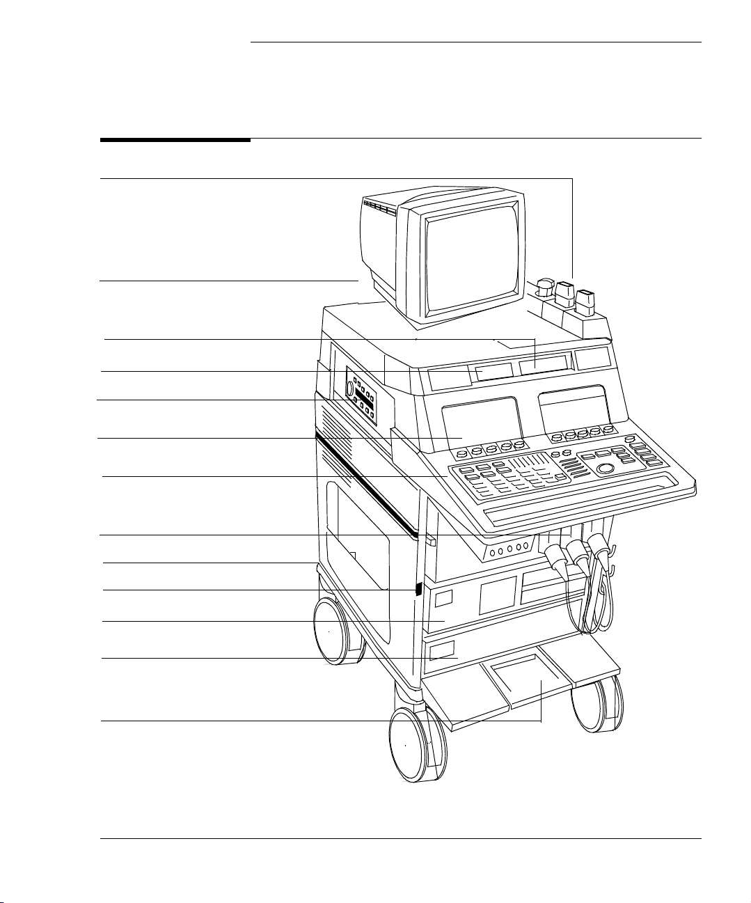
Transducer holders
Tilt and swivel monitor
Optical disk drive
Service floppy disk drive
Optional VCR
Touch panels
1The System
Main Components
Keyboard controls
Transducer connections
Circuit breaker (on back)
Main power switch
Optional peripheral
Live-3D or IDI PC
or other peripheral
Wheel lock
6apc0147
Revision D.0 1-1
ssn January 28, 1999 C:\WINNT\Profiles\dapowell\Desktop\D.0 Books\CD FILES
ssn February 10, 1999 C:\WINNT\Profiles\dapowell\Desktop\D.0 Books\CD FILES SONOS D.0\System
Basics D.0\Frame Files\1CH.FM add.2
Page 24
The System
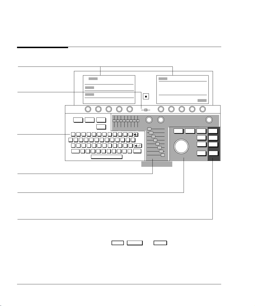
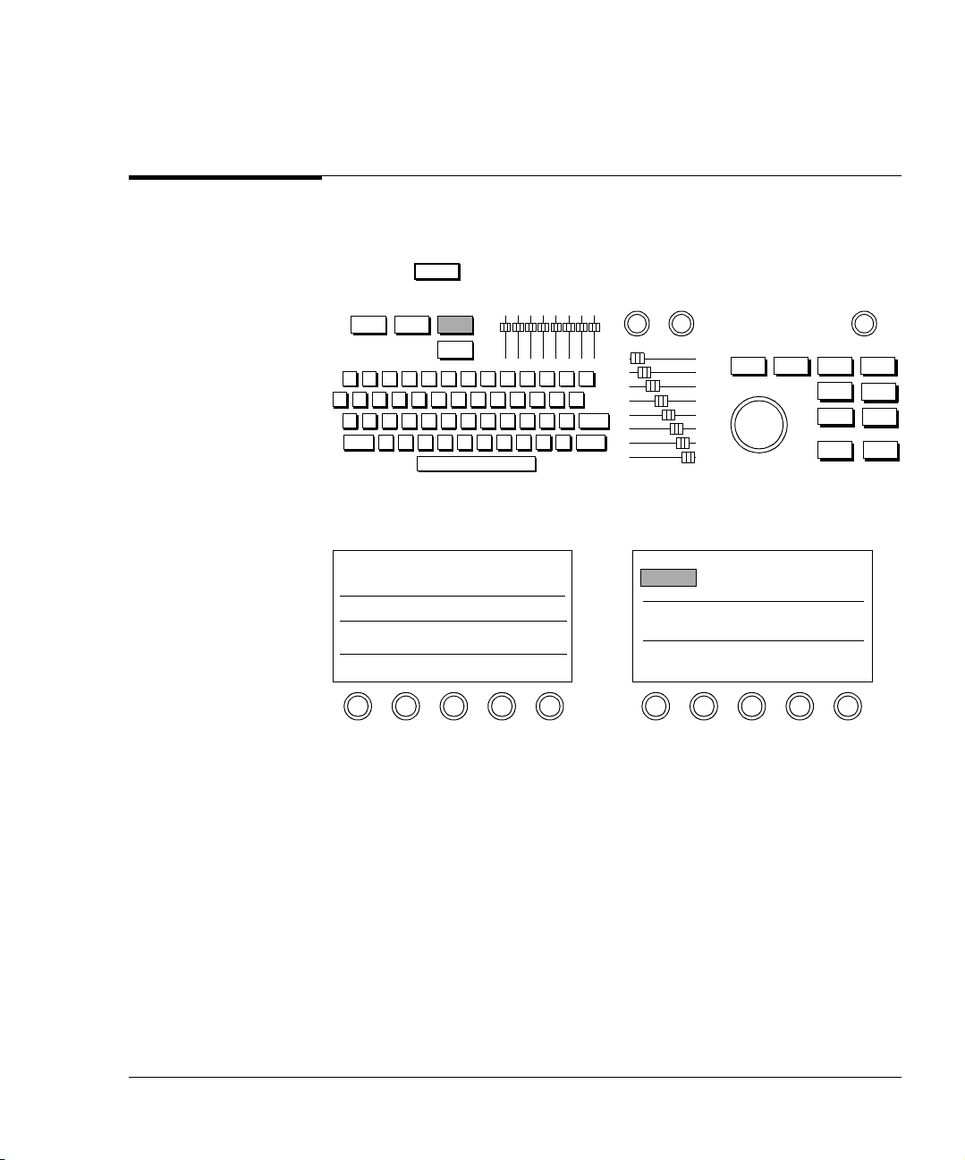
Control Panel
Touch panels contain most
of the controls
Volume contro l
Alphanumeric keyboard
and function keys
Control Panel
Reset Test Setup
Patient
ID
123456789
QWER
Tab
Cps
ASDF
Lck
Shift ZX
TYUI
GHJ K
CVBNM
LGC
0-=
OP
L;‘
,./
[]
Mic
Vol um e
Gain Compress Depth
PositionSize Erase Tape
Shift
Trace Acquire
Caliper Print
Enter Freeze
Image tuning controls
Measurement and trackball controls
Hardcopy and
Loop controls
Function keys, such as , , and , are active when their status
Setup Position Freeze
lights are on. Pressing these keys turns them on or off.
1-2 Revision D.0
Page 25

The System
Touch Panels
Touch Panels
When you touch a control, the system highlights it to indicate the control is
active. System controls, such as Presets, Too ls , Physio, and Probes are located
on the left touch panel. Imaging modalities, such as 2D, MMode, Color, PW,
CW, and Angio appear on the primary right touch panel. Additional touch and
rotary controls pertaining to the selected modality also appear on the primary
right touch panel. In some cases, you will see Secondary Controls on the right
touch panel. Touching this control displays another touch panel that contains
controls that are not used as frequently.
Depending on the system you have and on your system’s options, you might not
see some of the controls shown in this guide. Also, the illustrations in this book
show only the pertinent controls required to access a function.
To turn off an active (highlighted) control, touch it.
Revision D.0 1-3
ssn February 10, 1999 C:\WINNT\Profiles\dapowell\Desktop\D.0 Books\CD FILES SONOS
D.0\System Basics D.0\Frame Files\1CH.FM add.2
Page 26

The System
Touch Panels
Left Touch Panel
Contains system-specific controls.
Each rotary control adjusts
the highlighted control
above it. To change the
value displayed, turn the
rotary control to the right or
left.
Right Touch Panel
Contains mode-specific controls.
Secondary
Controls
Secondary Touch Panel
Contains less frequently used controls.
Secondary
Controls
1-4 Revision D.0
Page 27
System Power
All systems have a separate circuit-breaker switch on the back panel, near the
power-cord connection. This switch has on and off settings. If the
SONOS system does not power up when the main power switch is turned on, this
circuit-breaker may have tripped or may be set to off. If this happens, turn the
circuit breaker completely off and then back on. Then turn system power on
using the main power switch.
Systems without PCs
The main power switch immediately turns the system on and off .
NOTE When the system is turned off, standby power remains on.
The System
System Power
Systems with PCs
NOTE Systems with PCs are equipped with circuitry to properly shut down the PC.
Following the procedure described below helps to increase the reliability of the
system.
• Turning the main power switch on turns on both the SONOS system
and the PC.
• Turning the main power switch off
three seconds starts the controlled PC-shutdown procedure:
1 An onscreen message displays:
Please wait while the system shuts down.
2 The SONOS system then begins to shut down. It disables all controls and
suspends scanning and other processing.
Revision D.0 1-5
ssn February 10, 1999 C:\WINNT\Profiles\dapowell\Desktop\D.0 Books\CD FILES SONOS
D.0\System Basics D.0\Frame Files\1CH.FM add.2
and leaving it off for approximately
Page 28

The System
System Power
NOTE Turning the main power switch back on before the shutdown message is
displayed stops the shutdown procedure. The system and PC remain on.
NOTE After the shutdown message has displayed, the system ignores further changes to
the main power-switch setting, and shutdown completes. However, if you change
the power-switch setting after the shutdown message is displayed, the new
setting takes over after shutdown. For example, if you turn the main power
switch back on during the final stages of shutdown, both the system and PC
power up after shutdown completes.
3 After a short delay (typically less than 30 seconds), the PC shuts down.
4 A few seconds later, the SONOS system completes shutdown, but standby
power remains on.
CAUTION If you disconnect the power cord before system shutdown completes, the PC may
not shut down properly.
If you turn system power off before the PC boots up completely, the PC may not
shut down properly.
NOTE If the PC does not power up when the SONOS system powers up, turn the main
power switch off, wait for the system to power down completely, and then power
the system back up. If the PC still does not power up, turn the PC power on by
pressing the power button on the upper-left front corner of the PC.
1-6 Revision D.0
Page 29
Setting Up the System
The System
Setting Up the System
1. Press .
Setup
Setup
2. Touch System.
System
3. Perform Setup tasks described in the following sections.
Revision D.0 1-7
ssn February 10, 1999 C:\WINNT\Profiles\dapowell\Desktop\D.0 Books\CD FILES SONOS
D.0\System Basics D.0\Frame Files\1CH.FM add.2
Page 30
The System
Setting Up the System
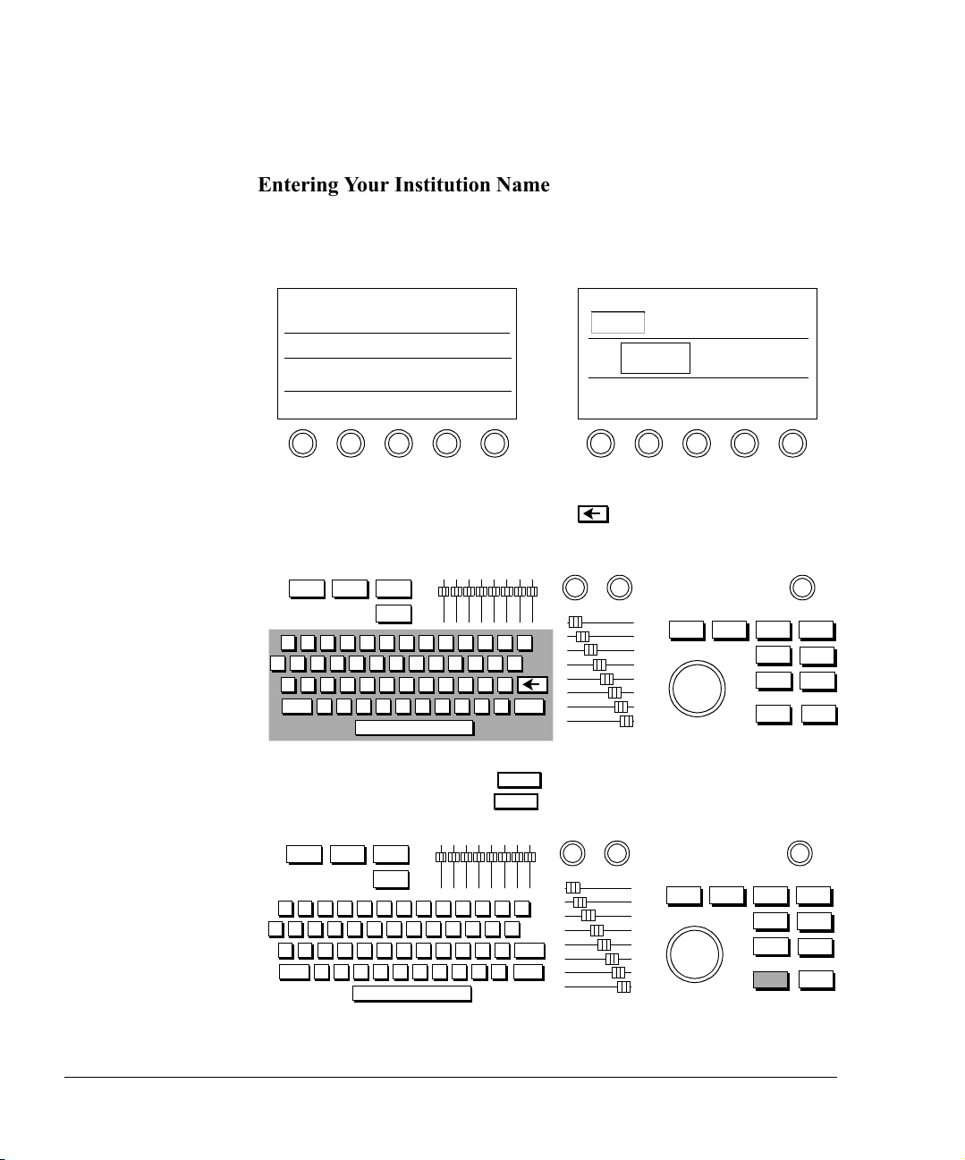
Entering Your Institution Name
1. Touch Institute Name.
System
Institute
Name
2. Type the name of your institution. You can type up to 32 characters on
two lines. If you make a mistake, use to erase the previous
characters.
3. When you are done, press twice quickly, or with the trackball,
highlight Okay and press .
Enter
Enter
Enter
1-8 Revision D.0
Page 31

The System
Setting Up the System
Setting the Date
1. Turn the Ye ar rotary control to the right to increase the year setting, or
to the left to decrease it.
System
Year
1999
2. Turn the Month rotary control to the right to select a month later in the
year, or to the left to select an earlier month.
System
Month
May
3. Turn the Day rotary control to the right to increase the day of the
month, or to the left to decrease it.
System
Day
19
Revision D.0 1-9
ssn February 10, 1999 C:\WINNT\Profiles\dapowell\Desktop\D.0 Books\CD FILES SONOS
D.0\System Basics D.0\Frame Files\1CH.FM add.2
Page 32

The System
Setting Up the System
Setting the Time
1. Turn the Hour rotary control to the right to increase the hour setting, or
to the left to decrease it. The system uses a 24-hour format.
System
Hour
13
2. Turn the Minute rotary control to the right to increase the minutes
setting, or to the left to decrease it.
System
Minute
58
1-10 Revision D.0
Page 33

Setting Up the System
Adjusting the Control Panel and Touch Panel Lighting
The System
Tip: Keep the Touch
Light setting as low as
possible for the
ambient light.
1. To adjust the lighting of the touch controls, touch the Touch Light
control and turn the To uch Li g ht rotary control to the right to brighten
the touch controls, or to the left to dim them.
System
Tou ch
Light 6
2. To adjust the lighting of the hard controls, keyboard, and sliders, touch
Backlight and turn the Backlight rotary control to the right to brighten
it, or to the left to dim it.
System
Backlight
8
NOTE To retain system settings, save them to a preset. See “Creating Presets” on
page 3-6.
Revision D.0 1-11
ssn February 10, 1999 C:\WINNT\Profiles\dapowell\Desktop\D.0 Books\CD FILES SONOS
D.0\System Basics D.0\Frame Files\1CH.FM add.2
Page 34

The System
Setting Up the System
Adjusting the Monitor Position
You can move the monitor up and down to find the position that is most
comfortable for you.
CAUTION Do not push the release bar under the center front of the monitor unless you want
to take the monitor off its base. See the Safety and Standards Guide for
information on removing the monitor and moving the system.
1-12 Revision D.0
Page 35

The System
Setting Up the System
Calibrating the Monitor
CAUTION You must calibrate the monitor lighting correctly, or improper adjustment of
system controls can occur. This can result in poor real-time image quality, VCR
recording quality, or print quality.
There are two versions of SONOS monitor. You calibrate one using brightness/
contrast dials. You calibrate the other using brightness/contrast push buttons.
Calibrating monitors with brightness/contrast dials on the front
Tip: Adjust monitor
lighting when the
ambient room lighting
changes, such as for
bedside studies.
1. On the monitor, turn the contrast dial up just until the top grayscale bar
looks pure, bright white. Once it looks pure white, do not continue to
turn the contrast dial.
White grayscale bar
Black grayscale bars
6apc0158
Revision D.0 1-13
ssn February 10, 1999 C:\WINNT\Profiles\dapowell\Desktop\D.0 Books\CD FILES SONOS
D.0\System Basics D.0\Frame Files\1CH.FM add.2
Page 36

The System
Setting Up the System
2. On the monitor, turn the brightness dial down just until the bottom
grayscale bar (the 16th bar) looks pure black and disappears into the
screen background. When the monitor is properly calibrated, 15
grayscale bars are visible, running from white (top) to nearly black
(bottom).
6apc0158
NOTE While not a direct danger to patient or operator safety, ambient magnetic fields
may affect the colors that are displayed on the imaging screen. To remove the
effects of this interference, periodically degauss the monitor. Push up on the
degaussing button located underneath the front-right corner of the monitor case.
Calibrating monitors with brightness/contrast push buttons on the front
Tip: Adjust monitor
lighting when the
ambient room lighting
changes, such as for
bedside studies.
1. On the monitor, press and hold the right contrast button only until the
top grayscale bar looks pure, bright white. Once it looks pure white,
release the button.
White grayscale bar
Black grayscale bars
+++++
--------
+
++
1-14 Revision D.0
Page 37

The System
Setting Up the System
2. On the monitor, press and hold the left brightness button only until the
bottom grayscale bar (the 16th bar) looks pure black and disappears
into the screen background. When the monitor is properly calibrated,
15 grayscale bars are visible, running from white (top) to nearly black
(bottom).
+++++
NOTE While not a direct danger to patient or operator safety, ambient magnetic fields
may affect the colors that are displayed on the imaging screen. To remove the
effects of this interference, periodically degauss the monitor. Press the contrast
--------
+
++
- and + buttons simultaneously. The displayed image may briefly distort, but will
quickly return to normal.
Revision D.0 1-15
ssn February 10, 1999 C:\WINNT\Profiles\dapowell\Desktop\D.0 Books\CD FILES SONOS
D.0\System Basics D.0\Frame Files\1CH.FM add.2
Page 38

The System
Using the Foot Switch
Using the Foot Switch
If you are using the foot switch, plug it into the back of the system into the
connector labelled Foot Switch.
Use the foot switch as follows:
• Left pedal to freeze
• Middle pedal to print
• Right pedal to tape
See Using 3-Dimensional and BiPlane Imaging Guide for information about
using the foot switch to acquire Full Volume images in Live-3D mode.
See Using Stress Echocardiography Guide for information on using the foot
switch during a stress exam.
See Using Contrast Imaging for information on using the foot switch during
contrast imaging.
WARNING Do not use the foot switch in the operating room. IEC 601-1 specifies
that foot-operated control devices used in the operating room must
be of watertight construction. The foot switch supplied with the
ultrasound system meets only drip-proof construction
requirements.
1-16 Revision D.0
Page 39

The System
Supplies and Accessories
Supplies and Accessories
To order supplies and accessories from within the U.S.A., visit:
http://shop.medical.philips.com
or call Medical Supplies at 1-800-225-0230.
From other countries, contact your local Philips representative or sales office.
Revision D.0 1-17
ssn February 10, 1999 C:\WINNT\Profiles\dapowell\Desktop\D.0 Books\CD FILES SONOS
D.0\System Basics D.0\Frame Files\1CH.FM add.2
Page 40

The System
Supplies and Accessories
1-18 Revision D.0
Page 41

2 Transducers
Introduction
This chapter provides information about
• Connecting transducers (page 2-2)
• Activating transducers (page 2-4)
• Disconnecting and storing transducers (page 2-5)
• Troubleshooting transducers (page 2-6)
NOTE Be sure that you use only Philips-approved transducers for your ultrasound
system.
See the Transducer Reference, Safety and Standards Guide, and
Using 3-Dimensional and BiPlane Imaging Guide for specific information about
Philips ImagePoint and SONOS transducer specifications, cleaning,
maintenance, and applications (including the x4 transducer used for Live-3D and
BiPlane imaging).
Revision D.0 2-1
ssn February 10, 1999 C:\WINNT\Profiles\dapowell\Desktop\D.0 Books\CD FILES SONOS
Page 42

Transducers
Connecting Transducers
Connecting Transducers
Imaging Transducers
1. With the latch in the vertical position, insert the transducer
connector. Never force a transducer into place. If you feel any
resistance, check the pin positions and try reinserting it.
T4
T1
Ver tical
T2
T3
6apc0148
2. Lock the connector by flipping the transducer lever to horizontal.
T4
T1
Horizontal
T2
T3
2-2 Revision D.0
Page 43

Nonimaging Doppler Pencil Transducers
1. Align the connector’s prongs with the receptacle.
T4
Transducers
Connecting Transducers
T1
2. Insert the connector.
T1
T2
T2
T3
6apc0149
T4
T3
6apc0148
Revision D.0 2-3
ssn February 10, 1999 C:\WINNT\Profiles\dapowell\Desktop\D.0 Books\CD FILES SONOS
Page 44

Transducers
Activating Transducers
Activating Transducers
1. Touch Probe.
Probe
2. Touch the control indicating where the transducer is connected.
Probe
Left Center Right Nonimage
2-4 Revision D.0
Page 45

Disconnecting and Storing Transducers
Disconnecting and Storing Transducers
1. Unlock and remove the transducer.
Transducers
T4
T1
T2
T3
Unlocked
6apc0148
2. Store external imaging transducers in the holders. Place connectors in
the individual side pockets to protect the pins. Store TEE transducers
on a wall-mounted rack.
2
0
b
e
F
0
1
7
0
:
9
1
:
4
1
s
’
n
e
r
d
l
i
h
C
Transducer holder
300e008a
NOTE See the Transducer Reference for information on caring for and cleaning your
transducer.
Revision D.0 2-5
ssn February 10, 1999 C:\WINNT\Profiles\dapowell\Desktop\D.0 Books\CD FILES SONOS
Page 46

Transducers
Transducer Troubleshooting
Transducer Troubleshooting
Always make sure that the active preset is appropriate for the study being
performed.
Symptoms Suggestions
Tip: Postproc, Edge
Enhance, and Persist
are 2D/BMode
controls. After
adjusting controls,
always check the
transducer position.
No Probe or ??
Probe is displayed
on the imaging
screen.
Place the transducer connector lock in the horizontal
position.
Make sure the correct transducer slot is selected on the
touch panel (Left, Center, Right, or Nonimage, under
Probe).
No image. Select the transducer on the touch panel (Left, Center,
Right, or Nonimage, under Probe).
Check to see if the transducer connector has any bent
pins; if not, reconnect the transducer to ensure it is
seated properly.
Image is too soft,
hazy, or gray.
Adjust the Postproc rotary control to increase
grayscale contrast.
Compress to reduce low-level echoes.
Persist to sharpen the image.
Adjust monitor settings.
Image has too much
contrast or is
grainy.
Adjust the Postproc rotary control to obtain the
desired image appearance.
Compress to increase low-level echoes.
Use a higher Frequency Fusion setting. Otherwise,
change to a higher frequency transducer.
For slow-moving structures, Persist to soften the
image.
Adjust monitor settings.
2-6 Revision D.0
Page 47

Symptoms Suggestions
Transducers
Transducer Troubleshooting
Need better
penetration.
Use the lower Frequency Fusion setting. Otherwise,
change to a lower frequency transducer. Use the LVO 1
or TCE1 setting if you are in Contrast Harmonic
imaging, and the Frequency Fusion 1 setting if you
are in Harmonic Fusion imaging.
Linear transducer
loses part of image.
Make sure gel completely covers the face of the
transducer.
NOTE If the pins on the transducer connector are bent and if the troubleshooting
suggestions do not help, contact your Philips Service Representative.
Revision D.0 2-7
ssn February 10, 1999 C:\WINNT\Profiles\dapowell\Desktop\D.0 Books\CD FILES SONOS
Page 48

Transducers
Transducer Troubleshooting
2-8 Revision D.0
Page 49

3Presets
Introduction
Tip: To remove the
preset name from the
screen, touch Preset
and Preset Name on
the left touch panel.
A preset is a group of specific control settings that optimize the system for the
exam you are about to perform. You use presets to establish initial settings such
as compression and gain values, color maps and processes, screen formats, and
acoustic power output levels. You can also use presets to determine patient
information screens, measurements, calculations, and annotation labels for the
selected study.
This chapter provides information about
• Philips-defined presets (page 3-2)
• Choosing presets (page 3-3)
• Modifying presets (page 3-4)
• Creating presets (page 3-6)
• Storing presets (page 3-8)
• Copying presets to a different SONOS system (page 3-9)
• Deleting presets (page 3-10)
Revision D.0 3-1
ssn February 10, 1999 C:\WINNT\Profiles\dapowell\Desktop\D.0 Books\CD FILES SONOS
D.0\System Basics D.0\Frame Files\3CH.FM add.2
Page 50

Presets
Philips-Defined Presets
Philips-Defined Presets
The system ships with Philips-defined presets for each exam type. Table 3-1
shows the number of Philips-defined presets by exam type and the number of
presets you can create.
Table 3-1 Philips-Defined Presets
Exam Type
Philips-defined
Presets
Available Customized
Presets
Cardiac 3 9
Va sc u la r 4 8
Abdominal 4 8
OB/GYN 4 8
Peripheral Vascular 4 8
Small Parts Exam 4 8
When you turn on or reset the system, it activates the last preset used. Before
starting a study, check the preset shown on the screen and, if necessary, touch a
more appropriate preset. Always select the Philips preset at the start of the study
to return to the initial values.
3-2 Revision D.0
Page 51

Choosing Presets
1. Touch Preset.
Preset
2. Touch the exam type (if applicable).
Presets
Choosing Presets
Preset
Cardiac
Exam
3. Touch the preset you want to use for this study.
Preset
Cardiac
Exam
Dr. R
Revision D.0 3-3
ssn February 10, 1999 C:\WINNT\Profiles\dapowell\Desktop\D.0 Books\CD FILES SONOS
D.0\System Basics D.0\Frame Files\3CH.FM add.2
Page 52

Presets
Modifying Presets
Modifying Presets
Tip: If you modify a
Philips preset, you
need to save it as a
new preset.
1. Touch the preset you want to alter. You can modify all Philips and
custom presets.
Preset
Cardiac
Exam
Dr. R.
2. Adjust controls to display the image as you want to see it.
DepthGain Compress
3-4 Revision D.0
Page 53

Presets
Modifying Presets
Tip: Be sure the
Annotation labels
and Analysis
measurements and
calculations are
appropriate for the
new preset. For
more information
see Chapter 8,
Chapter 9, and
Chapter 10.
3. To change Setup values, such as lighting and display options, press
Setup Setup
and make the necessary adjustments. Press again to exit
Setup mode.
Setup
4. With Preset active, touch Save Preset.
Preset
Save
Preset
5. Select Modify Current with the trackball and press . To keep
the current name, quickly press
Enter
press . To rename the preset, type a new name and quickly press
Enter Enter
twice, or highlight Okay and press .
Save Preset
Active Exam Type:
Active Preset Type:
Active Preset Name:
Create New
Modify Current
Enter
twice or highlight Okay and
Cancel
Enter
Revision D.0 3-5
ssn February 10, 1999 C:\WINNT\Profiles\dapowell\Desktop\D.0 Books\CD FILES SONOS
D.0\System Basics D.0\Frame Files\3CH.FM add.2
Page 54

Presets
Creating Presets
Creating Presets
You can define your own presets for each exam type and are only limited by the
amount of available space on the touch panel. To create a new preset, use the
following procedure:
1. Touch Preset.
Preset
Exam
Vas cular
Exam
Cardiac
2. Touch a preset of the same exam type as the one you want to create.
This ensures that most system settings, including annotation labels and
analysis measurements, are appropriate for the new preset.
Preset
Vas cular
Exam
TCD
3-6 Revision D.0
Page 55

Creating Presets
3. Adjust the controls to display the image as you want to see it. To
change Setup values, such as lighting and display options, press
and make the necessary adjustments. Press again.
Setup
4. Touch Save Preset.
Preset
Save
Preset
Presets
Setup
5. Highlight Create New with the trackball and press . You are
Enter
prompted to name the new preset. Give the preset a unique name and
quickly press
Enter Enter
twice or select Okay and press .
Save Preset
Active Exam Type:
Active Preset Type:
Active Preset Name:
Create New
Modify Current
Cancel
6. Type the name of the new preset into the Create New Preset window
and select Okay and press
Enter
.
Revision D.0 3-7
ssn February 10, 1999 C:\WINNT\Profiles\dapowell\Desktop\D.0 Books\CD FILES SONOS
D.0\System Basics D.0\Frame Files\3CH.FM add.2
Page 56

Presets
Storing Presets
Storing Presets
You can store modified or newly created presets, and are only limited by the
amount of available space on the touch panel. To store a modified or new preset,
use the following procedure:
1. After you have finished modifying or creating a preset to your
satisfaction (as described on page 3-4 or page 3-6), with Preset active,
touch Save Preset.
Preset
Save
Preset
Tip: Also save new
or modified presets
to a floppy diskette,
so you can restore
them in case of a
system failure. See
“Floppy Drive” on
page 4-3 for more
information.
2. To save a modified preset, select Modify Current with the trackball
and press .
Enter
To save a newly created preset, select Create New with the trackball
and press .
To keep the current name, quickly press twice or highlight Okay
and press . To rename the preset, type a new name and quickly
press twice, or highlight Okay and press .
Enter
Enter
Enter
Enter Enter
Save Preset
Active Exam Type:
Active Preset Type:
Active Preset Name:
Create New
Modify Current
Cancel
3-8 Revision D.0
Page 57

Copying Presets to a Different SONOS System
Copying Presets to a Different SONOS System
To copy presets from one SONOS system to another, do the following:
1. On the system that is currently using the preset, store the preset on a
floppy diskette using the Backup Preset control.
2. Insert the diskette in the SONOS system that you want to upgrade.
3. Touch Add Preset (which is below Restore Preset on the touch panel).
This adds all presets from the disk to the system’s current presets.
(Nonpreset files on the disk are ignored.)
4. If you did not want to add some of the presets on the disk, you can
delete them from the system using Delete Preset (see “Deleting Pre-
sets” on page 3-10).
Presets
Revision D.0 3-9
ssn February 10, 1999 C:\WINNT\Profiles\dapowell\Desktop\D.0 Books\CD FILES SONOS
D.0\System Basics D.0\Frame Files\3CH.FM add.2
Page 58

Presets
Deleting Presets
Deleting Presets
If the preset memory is full, you may have to delete a preset before creating new
ones. You cannot delete Philips presets, but you can delete customized presets.
1. Touch the preset you want to delete.
Preset
Cardiac
Exam
Dr. R
2. Touch Delete Preset.
Preset
Cardiac
Exam
Delete
Preset
3. To confirm the deletion, highlight Okay with the trackball and press
Enter Enter
. To retain it, highlight Cancel and press .
Delete Preset
Active Exam Type:
Active Preset Type:
Active Preset Name:
Delete this preset?
Okay
Cancel
3-10 Revision D.0
Page 59

4 Peripheral Devices
Introduction
WARNING This system has been investigated to the requirements of IEC 601-1,
with peripherals that are powered by the built-in isolation
transformer. Anyone who uses the system with peripherals that are
powered from a separate wall receptacle is considered to be
configuring a medical system, and is therefore responsible that the
system complies with the requirements of the IEC 601-1-1. If you
have additional questions, contact your Philips representative.
This chapter provides information about the SONOS
• System monitor (page 4-2)
• Floppy drive (page 4-3)
• Optical disk drive (page 4-5)
•PC (page 4-6)
See the
manufacturer’s
manuals for more
details on the VCR
and printer.
•VCR (page 4-6)
•Printer (page 4-10)
• RS-232 interface (page 4-20)
• Remote service feature (page 4-22)
NOTE Optional peripherals shipped with your ultrasound system are configured at the
factory to optimize ease of use and image quality. Operator’s manuals from other
manufacturers may describe additional features on those devices. Note, however,
that modifying factory settings can potentially affect how those peripherals
operate with your system. To ensure that peripherals work as designed with your
system, it is recommended that you do not change peripheral settings.
Revision D.0 4-1
ssn February 10, 1999 C:\WINNT\Profiles\dapowell\Desktop\D.0 Books\CD FILES SONOS
Page 60

Peripheral Devices
System Monitor
System Monitor
Adjusting the Monitor Position
For information about adjusting the system monitor for user comfort, see
“Adjusting the Monitor Position” on page 1-12.
Calibrating the Monitor
There are two versions of the SONOS monitor. You calibrate one using
brightness/contrast dials. You calibrate the other using brightness/contrast push
buttons. For instructions, see “Calibrating the Monitor” on page 1-13.
4-2 Revision D.0
Page 61

Peripheral Devices
Floppy Drive
Floppy Drive
The Service Floppy drive allows you to
• Save and restore customized presets
• Format and erase floppy diskettes
• Upgrade software
• Install software options
Controls
Add Preset Reads a previously stored system configuration data set
from disk.
Backup Preset Saves system configurations, including presets and
other settings, to a formatted floppy diskette. Screen
instructions are provided.
Clear Diskette Erases all disk files.
Format Diskette Formats any manufacturer’s 3.5” floppy diskette to
DOS compatibility. If you have the Integrated Digital
Interface option, you must turn the system off then on
again after formatting a diskette.
Install Options Installs optional software provided by Philips. Only
used by Philips service organization.
Read Diskette Reads text files stored on a floppy diskette.
Restore Preset Retrieves previously stored system preset from the
floppy diskette. Screen instructions are provided.
Upgrade Software Installs system upgrade software provided by Philips.
Only used by Philips service organization.
Revision D.0 4-3
ssn February 10, 1999 C:\WINNT\Profiles\dapowell\Desktop\D.0 Books\CD FILES SONOS
Page 62

Peripheral Devices
Floppy Drive
Accessing the Service Floppy Disk Drive
1. Press .
Setup
Setup
2. Touch Service Floppy.
Service
Floppy
3. Select the option you want and follow the instructions. Press to
Setup
return to imaging.
Service
Floppy
Format
Diskette
Upgrade
Software
Clear
Diskette
Install
Options
Read
Diskette
Backup
Preset
Restore
Preset
Add
Preset
4-4 Revision D.0
Page 63

Tip: Older SONOS
systems may not be
able to read data
stored by newer
SONOS systems on
newer optical disks.
Peripheral Devices
Optical Disk Drive
Optical Disk Drive
5 1/4-inch
The following table describes the optical-disk media that can be used with the
SONOS system using a 5 1/4-inch optical-disk drive:
Drive Revision
4X SONOS 7500/5500
A.0 through B.0
Media Compatibility and
Capacity
1X (read only) 600 MB
2X (read/write) 1.2 GB
4X (read/write) 2.3 GB
8X SONOS 7500/5500
B.1 through D.0
1X (read only) 600 MB
2X (read only) 1.2 GB
4X (read/write) 2.3 GB
8X (read/write) 4.8 GB
3 1/2-inch
The following table describes the optical-disk media that can be used with the
SONOS system, using a 3 1/2-inch optical-disk drive:
Revision Media Compatibility and Capacity
SONOS 5500
B.1 and B.2
SONOS 7500/5500
D.0
(read/write) 540 MB
(read/write) 540 MB
or
(read/write) 2.3 GB
Revision D.0 4-5
ssn February 10, 1999 C:\WINNT\Profiles\dapowell\Desktop\D.0 Books\CD FILES SONOS
Page 64

Peripheral Devices
PC
PC
A PC is installed on systems that receive the optional Live-3D imaging software.
This PC allows users to perform the following Live-3D operations:
• Save study images to the PC disk.
• Review, retrieve, and delete studies that are stored on the PC disk.
• Export studies from the PC disk to the CD-ROM media.
For more information about these operations and about the PC’s controls, see the
Using 3-Dimensional and BiPlane Imaging Guide.
VCR
NOTE For information about using the VCR to videotape exams, see Chapter 6.
Controls
Primary
Color Adjusts playback color intensity.
EJECT Ejects the tape from the VCR.
FF Rapidly advances a VCR tape.
Frame Displays the next or previous tape frame. Available
during playback, when PAU SE is on.
Mic Enables and disables the microphone, to record external
sound onto a tape.
4-6 Revision D.0
Page 65

Peripheral Devices
VCR
PAUSE Pauses and resumes recording or playback, without
disengaging the VCR heads.
PLAY Activates VCR playback.
RECORD Indicates that the system is recording the display onto a
VCR tape.
REW Rapidly rewinds a VCR tape.
SEARCH Pauses the VCR playback picture and puts the system
into search mode.
Speed Adjusts the tape search speed. Available when
SEARCH is on.
STOP Stops any active VCR operation.
Tap e
Starts and pauses VCR recording.
Tap e Fi nd Displays the frame specified. The format you enter
must match the format used during recording (either the
time format using Tap e Ti m e or the number format
using Ta pe Nu mbe r ).
Tap e Numb er Lets you enter a number on the imaging screen that
matches the number recorded on the VCR tape. Ta pe
Number must be enabled in Setup to see this control as
part of the VCR control set.
Tap e Ti me Lets you enter a time (hours, minutes, and seconds) on
the imaging screen that matches the time recorded on
the VCR tape. Ta p e Tim e must be enabled in Setup to
see this control as part of the VCR control set.
VCR Play Displayed on the right touch panel, this indicates that a
VCR image is on the imaging screen. Touching VCR
Play stops VCR playback and displays the previous
format.
Revision D.0 4-7
ssn February 10, 1999 C:\WINNT\Profiles\dapowell\Desktop\D.0 Books\CD FILES SONOS
Page 66

Peripheral Devices
VCR
Setup
Blink, Normal, and Inverse are available for both Tap e N umb e r and Ta pe
Time. With VCR highlighted, press and select either Tap e Num b er or
Setup
Tap e Ti me . Turn the rotary control beneath the highlighted selection to select
Blink, Normal, or Inverse. Press again to return to imaging.
Setup
Blink Displays tape time or tape number in blinking
numerics.
Inverse Displays tape time or tape number in numerics within a
shaded box.
Normal Displays tape time or tape number in normal video
display.
Tap e Numb er Enables Tape N um ber, for entering a number on the
screen that matches the number recorded on the VCR
tape.
Tap e Ti me Enables Tap e T i me, for entering a time (hours, min-
utes, and seconds) on the screen that matches the time
recorded on the VCR tape.
4-8 Revision D.0
Page 67

VCR Troubleshooting
Symptoms Suggestions
Peripheral Devices
VCR
Tip: Always use high
quality tapes for best
results.
Tape controls do not
display.
Cannot hear sounds
on the tape.
Images are too light
or dark on playback.
Playback quality is
inferior.
Cannot view taped
images.
VCR images are
printed on the wrong
printer.
Make sure there is a tape in the VCR.
Turn up the Vol um e control.
Make sure the monitor and controls are
correctly set. See “Calibrating the Monitor” on
page 1-13 for details.
For tapes recorded with color, adjust Color during
playback.
To obtain and view Super VHS images, record on a
• Super VHS VCR (if your VCR has an S-VHS
switch, be sure it is on)
• Super VHS tape
Try viewing the tape on a Super VHS VCR. If a Super
VHS tape was recorded in S-VHS, you can only view
the images on a Super VHS VCR.
Setup
Press , touch Print, and adjust VCR [printer]
to display the printer to use for VCR images.
Revision D.0 4-9
ssn February 10, 1999 C:\WINNT\Profiles\dapowell\Desktop\D.0 Books\CD FILES SONOS
Page 68

Peripheral Devices
Printers
Printers
The SONOS system allows you to send an image to your local printer or to a
networked DICOM printer.
NOTE The DICOM Print support option must be installed by your Philips Customer
Engineer. The ultrasound system must include an Integrated Digital Interface
(IDI) configured for DICOM networking. The system must also be configured
for DICOM printers.
Printing an Image Locally
Use the following procedure to print using the SONOS printer.
1. Make sure the printer is on and has paper. Clean gel from your hands
before loading paper.
Printer
4-10 Revision D.0
Page 69

Peripheral Devices
Printers
Tip: If Quad
Format is on in
Setup, you must
press four
Print
times to produce a
four-image print.
2. Press .
Print
Print
Revision D.0 4-11
ssn February 10, 1999 C:\WINNT\Profiles\dapowell\Desktop\D.0 Books\CD FILES SONOS
Page 70

Peripheral Devices
Printers
DICOM Printers
DICOM print allows you to print ultrasound still frames to a networked DICOM
black and white or color printer. Images are automatically sent to the printer
when the study ends. When Network Autosend is enabled, a sheet of images is
printed when the sheet is full. If both color and black and white DICOM printers
are configured, the system can automatically send images to the appropriate
printer.
Setting Up DICOM Print
A DICOM rotary control appears on the Setup Print touch panel if the DICOM
printer is available, and has either two or four positions, depending on the
number of DICOM printers configured.
2D
System
UP-5600
Adjust
B/W
UP-890
Color
Color
UP-51MD
Print
VCR
UP-890
Angio
Report
External
Quad
Format
AQ
DICOM
<XXX>
If only one printer is configured, the DICOM rotary control choices are
• Off—Disables DICOM print.
• BW or Color—Sends acquired images to the DICOM printer.
4-12 Revision D.0
Page 71

Peripheral Devices
Printers
If the system is configured for both a color and a black and white DICOM printer,
the DICOM rotary control choices are
Tip: The settings that
you select must
match the settings of
the output device
(external printer) that
you want to use.
• Off—Disables DICOM print.
• Auto—The system sends acquired images to one of the DICOM printers,
depending on the image type.
- Monochrome images go to the DICOM black and white printer.
- Doppler spectral images go to the DICOM black and white printer even
if there is color in the reference section of the image.
- Colorized images with color go to the DICOM black and white printer.
- All other images with color go to the DICOM color printer.
• BW— All images print on the DICOM black and white printer.
• Color—All images print on the DICOM color printer.
Revision D.0 4-13
ssn February 10, 1999 C:\WINNT\Profiles\dapowell\Desktop\D.0 Books\CD FILES SONOS
Page 72

Peripheral Devices
Printers
Using DICOM Prints
Acquiring Images
When DICOM print is enabled, pressing or touching Acquire Frame
Acquire
when a still frame is displayed places the current image in the queue for DICOM
print. A print exposure indicator window is displayed for four seconds, at the
bottom right of the imaging screen.
If Network Autosend is on, SONOS sends a preselected number of images to
the printer. The images begin printing as soon as the printer has received the
specified number of images. If Network Autosend is off, the images do not start
printing until you touch End Study.
Example:
3 B/W
The exposure window shows the type of printer that will print the image and the
image count sent to that printer from the current study. In the example shown, the
system sends the image to the black and white DICOM printer, and the image is
the third one acquired in the study.
NOTE Deleting an acquired image from system memory does not change the exposure
count.
4-14 Revision D.0
Page 73

Peripheral Devices
Printers
Retrieving Stored Images for DICOM Printing
Images stored on the system’s hard disk or optical disk can be queued for
DICOM printing by using the Disk Retrieve control in Loop mode. After Disk
Retrieve loads an image into system memory, it can be printed to the DICOM
printer when the current study ends, provided the DICOM rotary control is
enabled.
1 Touch Disk on the left touch panel.
2 Touch End Study on the left touch panel.
3 The system
a. Saves all acquired still frames to disk.
b. Sends all acquired still frames to the DICOM printers.
c. Resets the print exposure counters to zero.
A network status window on the monitor shows the number of files being sent to
DICOM storage, and the status of the printers and DICOM servers.
Example:
Store: 3
B/W: Done
Color: Unavail
In the example, three files are loaded in the IDI waiting to be saved to a DICOM
storage device, all acquired black and white images were printed, and the
DICOM color printer is unavailable.
NOTE Images are processed based on the DICOM rotary control settings in Setup
Print, when the images are acquired. Changing the settings has no effect on
images already stored in system memory.
Revision D.0 4-15
ssn February 10, 1999 C:\WINNT\Profiles\dapowell\Desktop\D.0 Books\CD FILES SONOS
Page 74

Peripheral Devices
Printers
Selecting a Different Printer
Use the following procedure to select the print device.
Tip: If External
appears on the
screen, you can
connect an
external printer to
the system.
1. Press , and touch Print.
Setup
Print
2. Adjust controls to change where black and white, color, VCR, Report,
or Serial Port pages are printed.
Print
B/W
UP-910
Color
UP-5200
VCR
UP-5200
Report
UP-910
DICOM
B/W
3. Press to exit Setup mode.
Setup
4-16 Revision D.0
Page 75

Peripheral Devices
Printers
Printing an Analysis Report
After you complete configuring the RS232 interface, you can send analysis
reports to an external printer or to a PC.
1. Touch Analysis.
2. Touch Report.
Analysis
3. Press .
Print
Analysis
Results
Box
2D
Report
Revision D.0 4-17
ssn February 10, 1999 C:\WINNT\Profiles\dapowell\Desktop\D.0 Books\CD FILES SONOS
Page 76

Peripheral Devices
Printers
Printer Troubleshooting
Symptoms Suggestions
Tip: Always use high
quality paper for best
results.
Paper jams during
printing.
Fan the paper before loading it.
Store paper flat. If it is curled, try to flatten it before
loading.
Make sure paper trays fit securely into the printer.
Prints have white
lines.
Check the paper supply and remove any pieces with
gel on them. Always clean gel off your hands before
loading paper.
Four images print
instead of one on a
Setup
Press , touch Print, and touch Quad Format to
turn off printing of four images per sheet.
sheet.
Setup
Prints are coming
out of the wrong
printer, or are not
Press , touch Print, and adjust the appropriate
control to change where the black and white, color,
VCR, or Analysis report pages are printed.
printing at all.
Prints are blank. Make sure the paper is inserted properly.
4-18 Revision D.0
Page 77

Symptoms Suggestions
Peripheral Devices
Printers
The colors do not
look right.
Black and white
contrast or
brightness is not
ideal.
Setup
Press , touch Print, touch UP-5xxx Adjust
(control name depends on printer), and alter the
settings, as necessary. The default values for the
UP-5200 are
• Contrast – 6
• Brightness – 4
• Red, Green, Blue – 12
The default values for the UP-5600 are
• Contrast – 2
• Brightness – 14
•Red – 7
• Green – 8
•Blue – 7
For black and white printers, consult the
manufacturer’s
manual.
Revision D.0 4-19
ssn February 10, 1999 C:\WINNT\Profiles\dapowell\Desktop\D.0 Books\CD FILES SONOS
Page 78

Peripheral Devices
Configuring the RS-232 Interface
Configuring the RS-232 Interface
You can configure the RS-232 interface for sending analysis reports to either an
external printer or a PC. The RS-232 interface is a 25-pin connector port located
on the back of the ultrasound system (J1). See “Connecting the Ultrasound
System to a Modem” on page 4-23.
1. Press , and touch System.
Setup
2. Touch Serial Port.
System
Serial
Port
4-20 Revision D.0
Page 79

Peripheral Devices
Configuring the RS-232 Interface
3. Use the trackball to highlight a setting, and make your selections by typing
in the information. On the Serial Port Setup window, enter data such as
baud rate, stop and data bits, and select parity and print range according to
the external printer device that is connected.
Serial Port Setup
Baud Rate:
Stop Bits:
Data Bits:
Timeout Duration:
4. Press to finish and exit Setup mode. After you complete the setup
Setup
9600
1
8
30
bps
secs
Parity:
Print Range:
Even
Odd
None
All
Current
and selection of the Serial Port for printing analysis reports, the system
redirects the output of the analysis report to the serial port when you touch
the Print controls.
Revision D.0 4-21
ssn February 10, 1999 C:\WINNT\Profiles\dapowell\Desktop\D.0 Books\CD FILES SONOS
Page 80

Peripheral Devices
Using the Remote Service Feature
Using the Remote Service Feature
This option may or
may not be
available in your
local area. For
details, contact your
Philips Service
Representative.
The Remote Service feature gives your Philips Service Representative access to
the system via a modem.
This section describes how to use the Remote Service feature.
WARNING DO NOT use the Remote Service feature or the modem while imag-
ing a patient.
4-22 Revision D.0
Page 81

Analog output
Aux outputs for display
Red, Green, Blue, Sync
Hi Level (1VPP)
ECG Output
Peripheral Devices
Using the Remote Service Feature
Connecting the Ultrasound System to a Modem
1. Disconnect all transducers and other external peripherals.
2. Connect the modem to the RS-232C 25-pin connector port located on the back
of the ultrasound system (J1).
Line Level
Stereo Audio Out
Earth ground (symbol)
Auxiliary RS-232C port for
remote control
Connection to
foot switch control pad
Auxiliary super video output
RS170/CCIR composite output
PAL/NTSC
composite video output
TTL open collector closure
signal for remote printing
LAN connection for computer*
IEC symbol - Consult Documentation
* Do not connect telephone to LAN connector.
For details on how
to use the modem,
refer to the
manufacturer’s
documentation.
3. Connect the modem to a fax line, or to a dedicated analog phone line.
4. Turn on the modem. The system is now ready for Remote Service mode.
LAN
!
6AJL017
Revision D.0 4-23
ssn February 10, 1999 C:\WINNT\Profiles\dapowell\Desktop\D.0 Books\CD FILES SONOS
Page 82

Peripheral Devices
Using the Remote Service Feature
Selecting Remote Service Mode
1. To access the Test Menu, press .
TESTRESET
2. Use the trackball to select Remote Service Mode and press .
Test Menu
Run Basic Test
Run Extended Basic
Key PRocessor
Scan Converter
Scanner
Other Tests and Utilities
Test Setup
Run Time Error Log
System Information
Remote Service Mode
RST Error Log
To return to Imaging mode,
press
Tes t
.
Tes t
SETUP
Enter
3. After a short delay, the system displays a message indicating it is ready to
accept a call from the local Philips Service Center.
The system is in Remote Service Mode
Status
Idle
Exit Remote Service Mode
4-24 Revision D.0
Page 83

Peripheral Devices
Using the Remote Service Feature
Note that the
information in
the Status box is
not an indicator
that the Philips
Representative
is done working
on the system.
Note that if the
Status box reads
either Remote user
logged on, or
Working, and you
disconnect the
modem, delays in
servicing the system
can occur.
While the system is being worked on, the Status box is updated:
Idle Indicates the system is not logged on to remote service.
Remote User
Indicates the Service Center is connected to the system.
Connected
Working Indicates the system is logged on to remote service, and
is being worked on.
Exiting Remote Service Mode
After your lab is notified by the local Service Center that the ultrasound system is
ready to be used for imaging, follow these steps to return to live imaging.
1 Use the trackball to select Exit Remote Service Mode and press .
The system is in Remote Service Mode
Status
Idle
Exit Remote Service Mode
Enter
2 After the system warning message appears, highlight Okay with the trackball
and press .
Enter
WARNING:
The modem and modem cable
must be disconnected from
system prior to performing
any imaging.
Okay
3 Disconnect the modem from the system.
Revision D.0 4-25
ssn February 10, 1999 C:\WINNT\Profiles\dapowell\Desktop\D.0 Books\CD FILES SONOS
Page 84

Peripheral Devices
Using the Remote Service Feature
4 To exit from the Test Menu and return to Imaging mode, press .
Test Menu
Run Basic Test
Run Extended Basic
Key PRocessor
Scan Converter
Scanner
Other Tests and Utilities
Test Setup
Run Time Error Log
System Information
Remote Service Mode
RST Error Log
To return to Imaging mode,
press
Tes t
.
Tes t
5 To return to live imaging, touch 2D or another imaging mode.
WARNING Make sure the modem is disconnected from the system before
imaging a patient.
4-26 Revision D.0
Page 85

5 Physios
Introduction
Using SONOS physios, you can connect ECG and other physical sensors to the
patient and monitor their heart sounds, pulse, respiration, and ECG waveforms in
real time.
This chapter provides information about
• Physio imaging screen and touch panels (page 5-2)
• Physio controls (page 5-3)
• Setting up physios (page 5-7)
• Setting up triggering modes (page 5-8)
• Connecting physios (page 5-10)
• Viewing physios (page 5-12)
• Physio troubleshooting (page 5-14)
Revision D.0 5-1
ssn February 10, 1999 C:\WINNT\Profiles\dapowell\Desktop\D.0 Books\CD FILES SONOS
Page 86

Physios
Screen and Touch Panels
Heart sound waveform
Pulse waveform
Respiration waveform
Screen and Touch Panels
ECG waveform
300e050
PW
Physio
Rwave
Beep
Tri gger
ECG
ECG
Invert
Delay
Resp
15
Beats
2
Pulse
Suppress
Physio
ECG
Gain 40%
Hrtsound
Test
ECG
Position
5-2 Revision D.0
Page 87

Controls
Primary
Physios
Controls
Beats
AutoBeat
Sequence
Delay When Trigger ECG is active, updates the 2D, Color,
ECG Enables gain and position adjustment of the ECG
Gain [Gain ECG, Gain Pulse, Gain Resp, or Gain
Hrtsound Enables adjustment of Hrtsound Gain and Position.
Interval When Trigger Timer is active, adjusts the 2D, Color,
Invert Inverts the polarity of the ECG, Aux 1, Aux 2, and Resp
When Trigger ECG is active, adjusts the number of
beats between the triggered updates of a 2D, Color,
Angio, or Spectral Doppler image.
Defines the sequencing of R-wave acquisition of
images in Triggering mode.
Angio, or spectral Doppler image at a specified number
of milliseconds after the R-wave.
waveform. In 2D, Color, and Angio, the waveform
appears below the image and cannot be repositioned.
Hrtsound]
Adjusts the amplitude of the active waveform signal.
Activates the heart sound Filter control in Setup.
Angio, or Spectral Doppler image update interval, in
milliseconds.
waveforms.
Monitoring Mode Turns on or off the low MI grayscale image in real time
on the right side of a side-by-side display during a
trigger beat acquire. Helps maintain the imaging plane
without disrupting the contrast agent. Values are On/
Off. Only available in BW and Angio modes using the
s3 transducer in TCE1 and TCE2. See Using Contrast
Imaging for more information.
Revision D.0 5-3
ssn February 10, 1999 C:\WINNT\Profiles\dapowell\Desktop\D.0 Books\CD FILES SONOS
Page 88

Physios
Controls
Tip: To suppress the
ECG waveform, you
must turn ECG off in
Physio Setup.
Physio Suppress
Turns Hrtsound, Pulse, and Resp physio waveforms
on or off.
Position [Position ECG, Position Pulse, Position Resp or
Position Hrtsound]
Adjusts the vertical position of the active waveform.
Available in MMode, spectral CW and PW, and when
Acoustic Quantification (AQ) waveforms are
displayed.
Pulse Enables gain and position of the pulse waveform.
Available in Color mode and Spectral Doppler.
Resp
Enables adjustment of the respiration waveform, which
displays movement of the chest during respiration. The
respiration waveform is derived from the ECG leads.
RWave Beep Controls whether or not the system beeps during each
R-wave. Not available in Doppler modes.
Tes t Puts a test signal through the currently active physio
channel.
5-4 Revision D.0
Page 89

Physios
Controls
Trigger Selects the triggering mode: Off, ECG, Timer, Loop/
ECG or Loop/Timr. Trigger activates either Beats and
Delay or time Interval for triggering 2D, Color, Angio,
or Doppler (with or without spectral) updates.
Loop/ECG and Loop/Timr are available in Contrast
or AD only.
With Contrast active, Loop/ECG lets you acquire the
same portion of the cardiac cycle while the 2D, Color,
or Angio image is displayed in real time. With AD
active, Loop/ECG lets you acquire images while the
2D image is displayed in real time. Updates the
acquisition based on the selected beats and delay.
With Contrast active, Loop/Timr lets you acquire
images at a slower interval while the 2D, Color, or
Angio image is displayed in real time. With AD active,
Loop/Timr lets you acquire images while the 2D
image is displayed in real time. Updates acquisition in
milliseconds, based on selected intervals.
When PW is active, turning Trigger off activates
simultaneous Duplex Doppler mode.
Revision D.0 5-5
ssn February 10, 1999 C:\WINNT\Profiles\dapowell\Desktop\D.0 Books\CD FILES SONOS
Page 90

Physios
Controls
Setup
ECG Selects an input source for the ECG waveform, or turns
the waveform off.
ECG Output Lets you take the ECG signal from the ECG output on
the back of the system and use the signal as input to
another device.
Filter Removes frequencies below the hertz level specified.
Only available when Hrtsound Normal is activated.
Hrtsound Selects an input source for the heart sound waveform,
or turns the waveform off.
Pulse Selects an input source for the pulse waveform, or turns
the waveform off.
Resp Selects an input source for the respiration waveform, or
turns the waveform off.
Rwave Output Lets you take the ECG R-wave signal from the ECG
output on the back of the system, and use the R-wave
signal as input to another device.
For complete details about Physio controls for contrast imaging, see Using
Contrast Imaging.
WARNING Do not use ECG patient cables with detachable lead wires that have
exposed male pins. Electrocution could result if these pins are
plugged into an AC power.
5-6 Revision D.0
Page 91

Setting Up Physios
Physios
Setting Up Physios
1. Press , and touch Physio.
Setup
Physio
2. Turn the rotary controls to adjust the Physios setup for the waveforms
you want to view, or turn the rotary control to Off for those that you do
not need. Turn Normal to obtain the signal from a physio transducer
connected to the system, or AUX for an auxiliary signal from another
source.
Physio
Resp
ECG
Normal
Normal
Pulse
Aux 3
Hrtsound
Normal
3. Press to exit Setup mode.
Setup
Revision D.0 5-7
ssn February 10, 1999 C:\WINNT\Profiles\dapowell\Desktop\D.0 Books\CD FILES SONOS
Page 92

Physios
Setting Up Triggering Modes
Setting Up Triggering Modes
1. Touch Physio.
2. Use the Trigger rotary control to select ECG, Timer, Loop/ECG, or
Loop/Timr mode. (Loop/ECG and Loop/Timr only appear if
Contrast or AD is on. For complete details, see Using Contrast
Imaging).
2D
2D
Tip: To retain
Trigger Beats,
Delay, and Interval
settings, save them
to a preset.
Triggering presets
depend on study
type and imaging
mode.
Physio
ECG
Tri gger
ECG
Physio
Suppress
Tes t
3. Adjust Delay and Beats (or Interval if Trigger Timer is active) to set
up triggering.
Physio
ECG
Tri gger
ECG
Delay
5
Beats
2
Physio
Suppress
Gain 30%
Tes t
ECG
NOTE In PW and CW, if no R-wave is present, the ECG trigger does not appear.
5-8 Revision D.0
Page 93

Physios
Setting Up Triggering Modes
Tip: Triggered
images can only be
acquired in Contrast
and AD modes.
4. Turn the Trigger rotary control to Loop/ECG or Loop/Timr in
Contrast or AD mode, to view a real-time image and acquire triggered
images.
Physio
Tri gger
Loop/ ECG
Delay
5
Beats
2
ECG
Gain 16%
2D
5. Turn the Trigger rotary control to Trigger ECG in Contrast mode. The
Frames control appears and the system goes into Multiple Frame
Triggering mode (MFT). See Using Contrast Imaging for more
information about MFT.
Physio
AutoBeat
Sequence
Tri gge r
ECG
Delay
5
Beats
2
ECG
Gain 16%
Frames
2
2D
Revision D.0 5-9
ssn February 10, 1999 C:\WINNT\Profiles\dapowell\Desktop\D.0 Books\CD FILES SONOS
Page 94

Physios
Connecting Physios
Connecting Physios
NOTE Your system may not have all of the physios shown.
1. Make sure that ECG Normal is displayed in Setup. Insert the ECG
cable connector into the ECG receptacle under the keyboard.
ECG
ECG AUX RESP PULSE
PATIENT CONNECTION
ELECTRICALLY ISOLATED
2. Connect the pin connector to the ECG cable.
Right Arm
Left Arm
Left Leg
HEART
SOUND
300e003a
5-10 Revision D.0
Page 95

Physios
Connecting Physios
3. Attach the electrodes and ECG leads to the patient as shown. Proper
ECG lead placement is critical for receiving a good ECG and
respiration signal.
Right Arm
Left Arm
Left Leg
NOTE Lead placements in the drawing above are anatomically incorrect; however, this
placement obtains optimal triggering for AQ, CK, AD, and 3D.
4. Connect and attach cables for other physios you want to use. Make sure
Setup values match the connections.
ECG
ECG AUX RESP PULSE
PATIENT CONNECTION
ELECTRICALLY ISOLATED
HEART
SOUND
Revision D.0 5-11
ssn February 10, 1999 C:\WINNT\Profiles\dapowell\Desktop\D.0 Books\CD FILES SONOS
Page 96

Physios
Viewing Physios
Viewing Physios
NOTE The Pulse waveform is unavailable in 2D, Color, Angio, nonspectral Doppler
modes, and AQ.
1. Touch Physio. Only waveforms that you have set up appear. Physio
Suppress must be off to see all available waveforms.
Physio
2. Verify that the ECG complex size is correct for each mode by touching
the mode (2D, MMode, PW, CW, or AQ) and ECG. To set the size of
an active trace, adjust the Gain rotary control.
2D
ECG
ECG
Gain 16%
5-12 Revision D.0
Page 97

Viewing Physios
3. Check the trace positions by touching each mode and then each
waveform you want to see in that mode. Only one waveform control
can be active at a time. The Gain and the Position rotary controls
pertain to the active waveform.
If an active Trace is not displayed, touch Te st . If necessary, adjust
Position.
Physios
Physio
ECG Resp Pulse Hrtsound
Tes t
ECG
Gain 16%
Position
MMode
ECG
Revision D.0 5-13
ssn February 10, 1999 C:\WINNT\Profiles\dapowell\Desktop\D.0 Books\CD FILES SONOS
Page 98

Physios
Physio Troubleshooting
Physio Troubleshooting
Always make sure that the active preset is appropriate for the study being
performed.
Symptoms Suggestions
Physio does not
display.
Too many physios
display.
Waveform is too big
or too small.
The ECG or
respiratory
waveform contains
an artifact or
wanders
For physios other than ECG, make sure Physio
Suppress is off.
Check to ensure the physio cable is secure in the
correct connection and is correctly attached to the
patient.
Touch Te st to test physio signals.
For ECG and respiration signals, check the patient
cable, the connection to the system, the electrodes, and
the lead placement.
Adjust Gain and Position controls for the active
waveform. If there is no touch control for the physio
waveform you want to view, press , and make
Setup
sure this physio is set to Normal (for a physio
transducer connected to the system) or Aux (for an
external signal connected).
With Physio active, press , and set the physios
Setup
you do not want to see to Off.
Adjust the physio Gain and Position controls for the
active waveform.
Follow the electrode manufacturer’s suggestions for
skin preparation.
Put a little gel on the electrodes. They might be dry.
Reconnect the lead to the electrode, and check the
electrode placement on the patient.
5-14 Revision D.0
Page 99

Symptoms Suggestions
Physios
Physio Troubleshooting
2D reference image
does not update
System does not
stop beeping
Waveform shape is
wrong
Make sure 2D Hold or BMode Hold is off in CW and
PW modes.
Verify that is off. Verify that the ECG leads are
Freeze
connected properly.
Adjust Delay or Beats rotary control if an R-wave is
present, or Interval rotary control if there is no R-wave
(all Physio Trigger controls).
Adjust ECG Gain rotary control.
Touch RWave Beep to turn off the beep during each
R-wave.
Make sure each physio cable is secure in the correct
connection on the system, and that touch controls
match your selections.
For example, for ECG and Pulse waveforms, Physio
Setup should show ECG and Pulse set to Normal to
obtain the signal from a physio transducer connected to
the system, or to AUX for an auxiliary signal from
another source.
Revision D.0 5-15
ssn February 10, 1999 C:\WINNT\Profiles\dapowell\Desktop\D.0 Books\CD FILES SONOS
Page 100

Physios
Physio Troubleshooting
5-16 Revision D.0
 Loading...