

Page 1

Service Newsletter 2001 – BCU Audio 1/5
For internal use only PHILIPS
ISSUE SNL2001.06 (01-11-30)
Published by:
Service Depar tment Audio
BUSINESS CREATION UNIT AUDIO
06.01 TYPENUMBER(S): Philips CD-recorders and copy-protected Audio CDs
INFORMATION : A number of music record companies have introduced so-called
“copy-protected” CDs.These CDs aim to obstruct copying to CDR
discs via the PC while they are supposed to play on conventional CDplayers.
However, in practice, the copy-protected CDs might not play on all
models of Audio CD-recorders, DVD-recorders, PC-drives and in-car
CD-players because these CDs are no longer in accordance with the
CD Red Book specification.
If you get complaints from customers facing playback problems,
please inform them that the CD is likely to be faulty, and advice the
customers to take the CD back to the shop and ask for refund.We
suggest refraining from debates about details of the copy-protection
technology, as this technology is being applied by the music record
company, and not by Philips.
REMARKS :
06.02 TYPENUMBER(S): ACT7585, AX2000, AX2001, AX2002, AX2003, AX2004, AX2011,
AX5000, AX5001, AX5002, AX5003, AX5004, AX5006, AX5011,
AX5012, AX5013, AX5014, AX5014, AX5015, AX5016, AX5017,
AX5018, AX5021, AX5022, AX5023, AX5024, AX5025, AX5026
INFORMATION : In course of production, the microprocessor IC (item 7400) has been
changed to a new (cheaper) type.The software remains unchanged.
The new microprocessor can replace the original one without further
modifications.The codenumber of the new IC reads as follows:
7400 3103 308 84360 TMP86CH21F-AX5000.1
REMARKS : The new microprocessor has been implemented in production from
week 0140 onwards.
SERVICE NEWSLETTER
Page 2

06.03 TYPENUMBER(S): AZ1018
INFORMATION : In course of production, the original CD drive “DA11N” has been
replaced by the new ball-clamp version “DA11B1N” –
3103 309 05360.
When an old drive is replaced by a new one, the magnetic Clamper
Ring Assembly (item 423) must be removed as well.
REMARKS : New CD drives have been implemented in production from week
0141 onwards.
06.04 TYPENUMBER(S): AZ1138
INFORMATION : Correction to the Service Manual, Electrical par tslist:
The codenumber for the SDRAM IC KSA161622D is missing.
It should read:
IC3 9965 000 10689 KSA161622D (or HY75V161610DTC-7)
REMARKS :
06.05 TYPENUMBER(S): AZ1150, AZ1155
INFORMATION : To fix a problem during tuner search, the following capacitor on the
Front Board has been changed:
2413 4822 126 14225 56pF NP0 50V
REMARKS : The modification has been implemented in production from week
0136 onwards.
06.06 TYPENUMBER(S): AZ1150, AZ1155
SYMPTOM :
The set does not play MP3 CD-R / CD-RW discs.
CURE : The problem is caused by the recording for mat used by the customer.
The present hardware/software supports only ISO9600 standard.
UDF (Universal Disc Format) discs cannot be played on the set.
The customers should be advised to record their MP3 music discs
according to ISO9600 standard.
REMARKS : UDF discs can be identified on any UDF compliant MS-Windows PC
by opening the properties dialog of the corresponding CD-ROM drive.
1271IRIS CODE
Service Newsletter 2001 – BCU Audio 2/5
Page 3
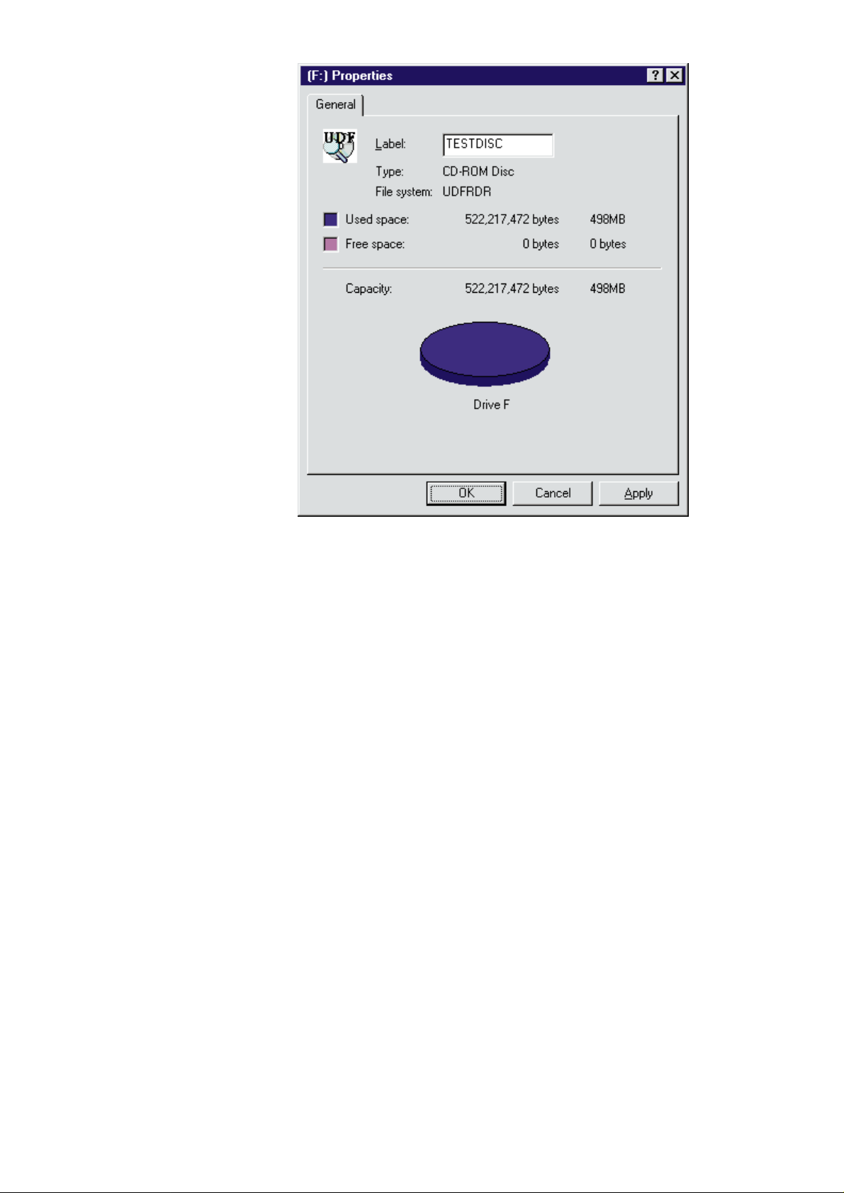
For UDF discs the file system is detected as “UDFRDR”, “C2UDFFS”,
“CDUDF” or similar, dependent on the operating system and the
installed drive software.A special UDF-icon is displayed optionally.
06.07 TYPENUMBER(S): CDR602/00S
INFORMATION : Correction to the Service Manual, Mechanical partslist:
The correct codenumber for WORDMARK “PHILIPS” SILVER
CDR602 reads:
14 3104 120 00290 WORDMARK “PHILIPS” SILVER CDR602
REMARKS :
06.08 TYPENUMBER(S): CDR800, CDR802, CDR820, CDR822
INFORMATION : Correction to the Service Manual, Mechanical partslist:
The correct codenumber for WORDMARK reads:
225 3104 120 00290 WORDMARK “PHILIPS” SILVER BACKGR.
REMARKS :
Service Newsletter 2001 – BCU Audio 3/5
Page 4

06.09 TYPENUMBER(S): FW-i1000/37
INFORMATION : AF8 BOARD – Changes in course of production:
• From production week 0125 onwards, the following components
have been changed to adapt the -3dB amplification reserve for CD:
Change 3513 4822 117 10833 10kΩ 1% 0,1W
Change 3514 4822 117 10833 10kΩ 1% 0,1W
Change 3515 4822 051 20472 4,7kΩ 5% 0,1W
Change 3516 4822 051 20472 4,7kΩ 5% 0,1W
• From production week 0125 onwards, the following components
have been changed/deleted to adapt the gain to +6dB for AUX and
to 0dB for CDR:
Change 3523 4822 117 11507 6,8kΩ 1% 0,1W
Change 3524 4822 117 11507 6,8kΩ 1% 0,1W
Change 3545 4822 051 20333 33kΩ 5% 0,1W
Change 3546 4822 051 20333 33kΩ 5% 0,1W
Delete 3688
Delete 3689
• From production week 0125 onwards, the following component has
been changed to adjust the Subwoofer output level:
Change 3684 4822 117 11507 6,8kΩ 1% 0,1W
REMARKS :
06.10 TYPENUMBER(S): FW-i1000/37
INFORMATION : The following components on the Supply & Left/Right Amplifier Board
have been changed to improve reliability:
Change 3308 4822 116 52175 100Ω 5% 0,5W
Change 3310 4822 116 52256 2,2kΩ 5% 0,5W
REMARKS :
06.11 TYPENUMBER(S): FW-i1000/37
INFORMATION : The following Tact Switches on the Front Board have been changed
to improve the tactile feeling:
1101, 1102, 1103, 1104, 1105, 1203, 1204, 1205, 1206, 1207, 1208,
1209, 1210, 1211, 1212, 1213, 1214, 1215, 1216, 1402, 1403, 1404,
1405, 1406, 1407, 1408, 1409, 1410, 1411, 1412, 1413, 1414, 1415,
1416, 1417, 1418, 1419
The new Tact Switches are available with codenumber
4822 276 13775.
REMARKS :
Service Newsletter 2001 – BCU Audio 4/5
Page 5

06.12 TYPENUMBER(S): FW-M55/22
INFORMATION : Correction to the Service Manual, Circuit drawing and Parts list for
Front Board:The codenumber and the article description of item 1408
should read:
1408 4822 242 11033 RES XTL 4,332MHz
REMARKS :
06.13 TYPENUMBER(S): MC-30 (for /37 USA version only)
INFORMATION : In course of production, the following parts have been modified to
meet the new 2002 UL safety requirements:
406 3140 117 63040 FRONT CABINET ASSY /37
426 3140 114 42050 CD TRAY /37
REMARKS : The modified parts will be implemented in production from week 0150
onwards.
06.14 TYPENUMBER(S): MC45, MC-50, MC-70
INFORMATION : Training Manual for the “3 Disc Tray Changer 3DTC” is available with
codenumber 3103 785 25140.
The document provides detailed mechanical intstructions on the
3DTC and covers the following topics:
• Replacing the CD drive
• Dismantling and reassembling of jammed trays
• Replacing the gears
REMARKS :
06.15 TYPENUMBER(S): MZ7/22, MZ7/34
INFORMATION : Correction to the Service Manual, Circuit drawing and Parts list for
Front Board:The codenumber and the article description of item 1408
should read:
1408 4822 242 11033 RES XTL 4,332MHz
REMARKS :
06.16 TYPENUMBER(S): SA100, SA101, SA107, SA125, SA126
INFORMATION : The software provided with the product does not support the new
Microsoft operating systems Windows 2000, Windows ME and
Windows XP.
Customers using Windows ME can download an updated version of
the free RealJukebox 2 Basic from Real Networks at the following url:
http://www.real.com
REMARKS :
Service Newsletter 2001 – BCU Audio 5/5
Page 6

Service Newsletter 2001 – BCU Audio 1/7
For internal use only PHILIPS
ISSUE SNL2001.05 (01-10-24)
Published by:
Service Depar tment Audio
BUSINESS CREATION UNIT AUDIO
05.01 TYPENUMBER(S): General CD Portable
INFORMATION : The Remote Control AY3767 (3103 309 72380) is no longer available
as service spare par t. It is superseded by the new Remote Control
AY3768 – 3140 118 50980.
The AY3768 has 4 buttons while the AY3767 had only 3.The Skip
back button on the AY3768 may not work with some models.
REMARKS :
05.02 TYPENUMBER(S): AE2380
SYMPTOM :
Reception is poor in all bands.
CURE : The problem might be caused by defective capacitors C37 and C38.
Exchange capacitors C37 and C38, 100nF 4822 126 13838
REMARKS : Improved capacitors are used in production from week 118 onwards.
05.03 TYPENUMBER(S): AQ6688
INFORMATION : The Flywheel Assemblies of the Tape Deck are now available as
service spare par ts and can be ordered with the following
codenumbers:
24 9965 000 10920 Flywheel Assembly (L)
44 9965 000 10921 Flywheel Assembly (R)
REMARKS :
X521IRIS CODE
SERVICE NEWSLETTER
Page 7

05.04 TYPENUMBER(S): AX1000, AX1001
INFORMATION : Correction to the Service Manual, Circuit Diagram Control/Supply part
The servo driver IC 7256 should read SA111259FTA.
In course of production the above mentioned IC has been replaced
by IC SA111259AFTA (a low power version).
The new IC requires an adapted supply voltage and thus diode
SB140 (pos. 6152) has been added along with.
The location of 6152 can already be found in the existing Ser vice
Manual.The codenumbers of the new components read as follows:
6152 5322 130 81917 SB140
7256 9322 171 12671 SC111259AFTA
REMARKS : The above modification has been implemented in production from
week 0135 onwards.
05.05 TYPENUMBER(S): AX2000, AX2001, AX2002, AX2003, AX2011, AX5000–AX5004,
AX5006, AX5011–AX5018, AX5021–AX5027
SYMPTOM :
Fuse 1251 is blown.
CURE : The problem might be caused by an unstable supply regulation
circuit. Solution is to change 2262 from 3,3nF to 100pF.
2262 4822 122 31765 100pF 5% 50V
REMARKS : The modification has been implemented in production from week
0127 onwards.
05.06 TYPENUMBER(S): AZ1030, AZ1035, AZ1050, AZ1055
INFORMATION : It might happen that sets are returned with broken Bracket-Cassette
(item 501).The broken area is around the holder for Cassette Door
Spring. From production week 0108 onwards the part has been
strengthened by increasing the wall thickness of the holder.
The improved Bracket-Cassette can be ordered as follows:
501 3103 304 64080 Bracket-Cassette
REMARKS :
05.07 TYPENUMBER(S): AZ1550, AZ1570, AZ1574, AZ1575
INFORMATION : In course of production the microprocessor has been changed to a
new version.The circuit and layout diagrams of the Control board and
Key board have been changed as well.
For repair infor mation of the new Control board and Key board
assemblies, refer to the following Service Information:
A01-555 3140 785 22840 for AZ1570, AZ1574 and AZ1575
A01-556 3140 785 22850 for AZ1550
REMARKS : The new microprocessors and the new boards have been
implemented in production from week 0135 onwards.
X111IRIS CODE
Service Newsletter 2001 – BCU Audio 2/7
Page 8

05.08 TYPENUMBER(S): AZ8352, AZ8357, AZ8562, AZ8567
INFORMATION : The potentiometer 3563 (4822 102 10453) is no longer available as
service spare par t. It can be replaced by 4822 102 10447.
REMARKS :
05.09 TYPENUMBER(S): CDR785, CDR786, FW-R7, FW-R8, FW-R88
SYMPTOM :
CDR tray does not open.The display shows “OPEN CDR” but the set
does not react on the Open/Close key.
When sets are brought in for repair with the above or similar failure
description the failure can hardly or not be reproduced. An exchange
of the CDR-module does not solve the problem.
CURE : There is no solution available for this problem.The customer has to
be informed that this failure will occur when the set is operated in a
certain sequence.
When the set hangs up it can be restarted by one of the following:
• pull mains cord off and plug it on again
• switch power off, wait 15s and switch power on again
(CDR785, CDR786 only)
REMARKS : The easiest way to reproduce the problem:
• open the CDR tray and remove the disc
• press PLAY (with the tray still open) and wait until the message
“INSERT DISC” appears
• change to another source (e.g. CD1, 2, 3, AUX)
• change source back to CDR
→ “OPEN CDR” is shown, but the tray does not open.
The CDR-module can only be restarted by a reset.
05.10 TYPENUMBER(S): EXP501, EXP503
INFORMATION : Correction to the Service Manual, Accessories (chapter 1-3):
AC/DC Adaptor AY3170 cannot be used for above mentioned sets
(insufficient output current).The correct adaptors read
AY3160/00A 4822 219 10257 for EXP501/00
AY3160/17 4822 219 10017 for EXP503/17
REMARKS :
9162IRIS CODE
Service Newsletter 2001 – BCU Audio 3/7
Page 9
05.11 TYPENUMBER(S): FW-C28, FW-C38, FW-C39, FW-C40, FW-C55, FW-C58, FW-C71,
FW-C72, FW-C80, FW-C85, FW-C90, FW-C200, FW-C220, FW-C280,
FW-C290, FW-C380, FW-C500, FW-C550, FW-C700, FW-C720, FWi1000, FW-M55, FW-P75, FW-P78, FW-P88, FW-P750, FW-C780,
FW-C870, FW-P900, FW-P880, FW-V28, FW-V39, FW-V55, FW-V83,
FW-V220, FW-V320, FW-V720
INFORMATION : Service Manual, Partslist for Tape mechanism
The Coil activator lever (pos. 20) is now available as service spare
part. It can be ordered with codenumber 9965 000 10777.
REMARKS :
05.12 TYPENUMBER(S): FW-M55, FW-V39, FW-V55, FW-V220, FW-V320, FW-V720
SYMPTOM :
The set does not play MP3 CD-R / CD-RW discs.
CURE : This problem is caused by the recording for mat used by the
customer.The present hardware suppor ts only ISO9660 standard,
UDF (Universal Disc Format) discs cannot be played on the set.
The customers should be advised to record their MP3 discs
according to ISO9660 standard.
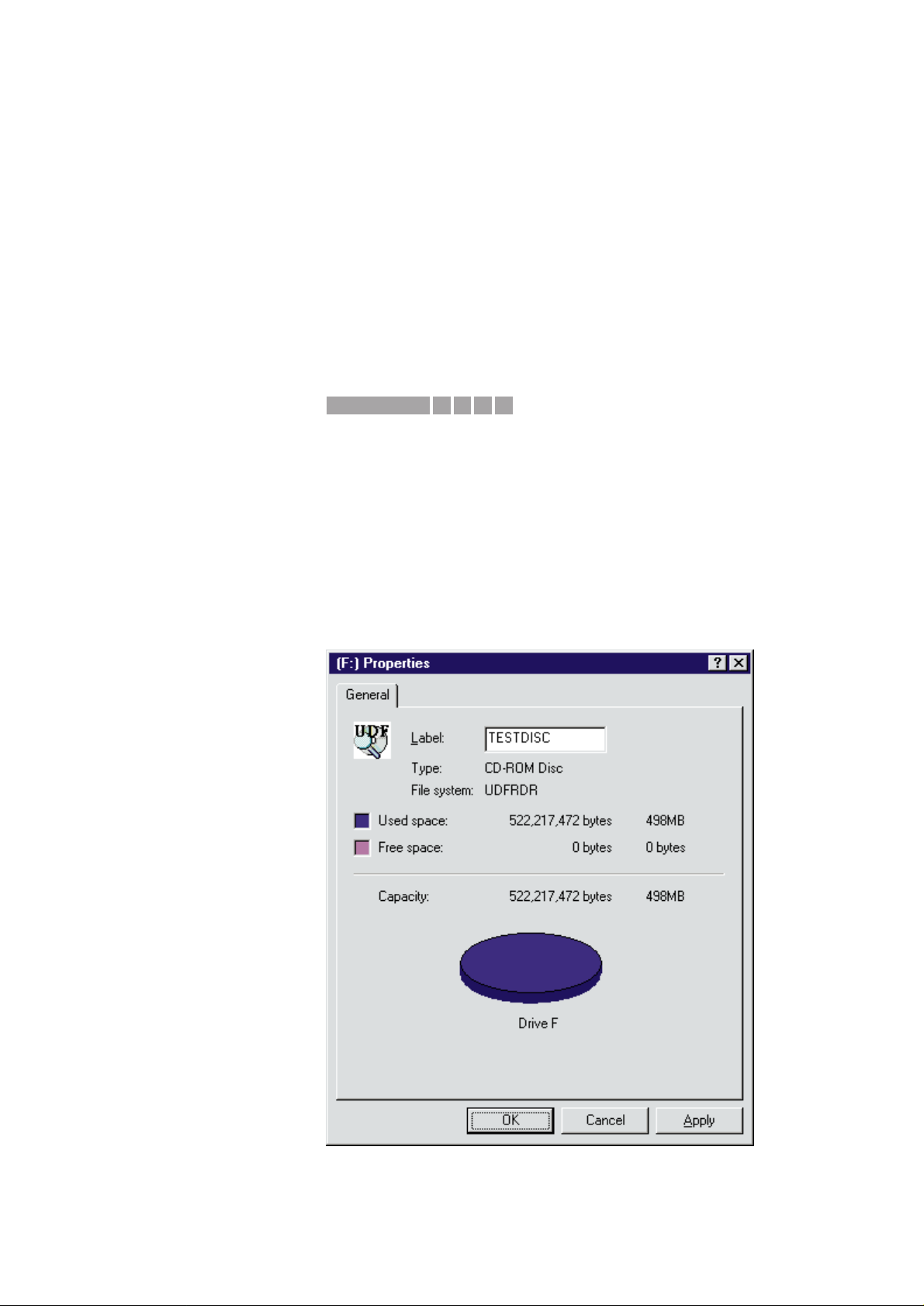
REMARKS : UDF discs can be identified on any UDF compliant MS-Windows PC
by opening the properties dialog of the corresponding CD-ROM drive.
For UDF discs the file system is detected as “UDFRDR”, “C2UDFFS”
or similar, dependent on the operating system and the installed dr iver
software. A special UDF-icon is displayed optionally.
1271IRIS CODE
Service Newsletter 2001 – BCU Audio 4/7
Page 10
05.13 TYPENUMBER(S): FW-V220, FW-V320
INFORMATION : Additional information to SNL2001.03.13 – MP3 noise problem
With this proposed modification the set might fail to detect the
presence of the microphone.This is solved by changing resistor
3682 on the Combi board to 100Ω (4822 051 30101).
REMARKS :
05.14 TYPENUMBER(S): FW-V220, FW-V320
INFORMATION : From production week 0127 onwards, the ETF7 Module has been
changed to ETF7 ND/DD/FF Ferro version.
Details of values and stuffing differences have already been
published on page 9-1 of the existing Service Manuals.
REMARKS :
05.15 TYPENUMBER(S): FW-V220, FW-V320
INFORMATION : In course of production the following changes have been introduced
to improve the VCD performance:
MPEG board 7202 software has been upgraded to version 12.
Front board microprocessor 7401 software has been upgraded to:
• version 23 for FW-V220 (recognized by print mark V220S52911)
and
• version 25 for FW-V320 (recognized by print mark V320S52921).
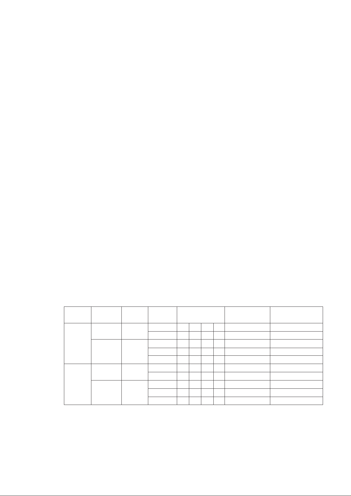
Note: Because matching between the 2 ICs is important, the table
below gives the var ious working combinations for the 2 ICs, their
software versions and codenumbers.
REMARKS :
Model
FW-V220
FW-V320
PC Board
MPEG
Front
MPEG
Front
Item No.
7202
7401
7202
7401
Software
Version
11
12
19
23
11
12
20
25
Workable
combination
Remarks
no longer available
with Cue/Review
no longer available
with Cue/Review
x
x
x
x
Service
code
-
9965 000 08683
-
9965 000 10199
-
9965 000 08683
-
9965 00010198
x
x
x
x
x
x
x
x
Service Newsletter 2001 – BCU Audio 5/7
Page 11

05.16 TYPENUMBER(S): FW-V220, FW-V320
INFORMATION : In course of production all the Tact Switches on the Front & Combi
board have been changed from 2422 128 02917 to 4822 276 13775
to improved the tactile feeling.
REMARKS :
05.17 TYPENUMBER(S): FW-V220, FW-V320, FW-V720
INFORMATION : When the set is in Tuner, Tape or AUX mode, resistor 3700 on the
Karaoke board can overheat. This is solved by changing resistor 3244
on the MPEG board from 220Ω to 4,7kΩ (4822 051 30472).
REMARKS :
05.18 TYPENUMBER(S): MC-20, MC-30
INFORMATION : In course of production, the Tape Deck module has been changed
from “ETF6” to “ETF8”. For repair information of the ETF8 tape deck
module refer to Service Information A01-554 (3140 785 22830).
REMARKS : ETF8 modules are used in production from week 137 onwards.
05.19 TYPENUMBER(S): MC-20, MC-30, MC-45, MC-50, MC-70, MC145, MC145C, MC148
SYMPTOM :
On the ETF6 mechanism, the lever (item 23) is deformed due to
overheating of Solenoid (item 20).The transistors 7612 and 7614 are
also burnt.
CURE : The problem is resolved by replacing:
1.Transistors 7612 and 7614 with higher current rating type
PMBT2907, codenumber 4822 130 11201
2. Solenoid assembly with improved version, codenumber
9965 000 10778
3. Coil Lever activator, codenumber 9965 000 10777
REMARKS : New Solenoids are used in production from week 0131 onwards.
05.20 TYPENUMBER(S): MC45, MC-50, MC-70
INFORMATION : Resistor 4124 on the Front Display Board has been changed from 0Ω
to 10Ω (4822 051 30109) to solve Tape head bounce problem when
play stops (additional head moving up and down).
REMARKS :
X611IRIS CODE
Service Newsletter 2001 – BCU Audio 6/7
Page 12

05.21 TYPENUMBER(S): MC45, MC-50, MC-70
INFORMATION : Resistor 3769 on the ETF6 board has been changed from 12kΩ to
5,6kΩ (4822 051 20562) to improve the S/N ratio on recordings with
Ferro cassettes.
REMARKS :
05.22 TYPENUMBER(S): MC-55
SYMPTOM :
When playing certain VCD’s, picture has blocking effect.
CURE : Solution is to replace the MPEG Decoder IC LS188 by the newer
version LS188C.The codenumber of the new IC reads:
IC601 9965 000 10820 LS188C
REMARKS : The new IC LS188C has been implemented in production from week
0132 onwards.
05.23 TYPENUMBER(S): MC-55
INFORMATION : Correction to Service Manual, Electrical par tslist:
The codenumber for the power amplifier LA4282 is missing:
IC802 4822 209 31855 LA4282
REMARKS :
05.24 TYPENUMBER(S): MC-70
INFORMATION : The length of Flex Cable 1136 has been increased from 18cm to
22cm to prevent dislodge from the socket during transpor tation.
The new cable is available with codenumber 3139 110 35900.
REMARKS :
X332IRIS CODE
Service Newsletter 2001 – BCU Audio 7/7
Page 13

Service Newsletter 2001 – BCU Audio 1/5
For internal use only PHILIPS
ISSUE SNL2001.04 (01-08-17)
Published by:
Service Depar tment Audio
BUSINESS CREATION UNIT AUDIO
04.01 TYPENUMBER(S): AE2110, AE2150, AE2155
INFORMATION : The Tuning Knob is now available with codenumber 9965 000 10427.
REMARKS :
04.02 TYPENUMBER(S): AX1000, AX1001
INFORMATION : Correction to Service Manual, Mechanical partslist
The codenumbers for below spareparts are wrong and should read:
402 3140 117 50250 Button-Set-Play/Stop
403 3140 117 60260 Button-Set-Prev/Next
407 3140 114 35770 Slider-Resume
408 3140 114 36180 Brake
409 3103 301 06500 Spring-Slider-Open 2
411 3140 114 35780 Slider-Open
412 3140 114 35800 Adapter-Button-Set-Play/Stop
413 3140 114 35810 Adapter-Button-Set-Prev/Next
414 3103 309 05320 CD-Drive DA23LNPH
REMARKS :
04.03 TYPENUMBER(S): AX1000, AX1001
INFORMATION : Additional information to Service Newsletter SNL2001.03.01:
AX1000 and AX1001 are produced with different CD-drives DA23LPH
and DA23LNPH.DA23LPH is no longer available as ser vice
sparepart and has been standardized to the DA23LNPH 3103 309 05320.
To replace DA23LPH by DA23LNPH, the Microprocessor IC 7400 has
to be replaced too.
7400 3140 110 50980 (matches with DA23LPH) or
7400 3140 110 51120 (matches with DA23LNPH)
REMARKS : Above infor mation can also be found in Service Manual
3140 785 22550, page 5-2.
SERVICE NEWSLETTER
Page 14

04.04 TYPENUMBER(S): AZ1110, AZ1111, AZ1112, AZ1114, AZ1116, AZ1117, AZ1118,
AZ1119, AZ8084, AZ8085, AZ8086, AZ8087
INFORMATION : Correction to Service Manual:
There are some mistakes in the CD Service Test Program.
• To enter the Service Program, hold
PLAY & STOP
buttons
depressed while switching CD mode ON.
• Disc Motor test : press
MODE
button and the disc motor turns
clockwise.
• Display Test : the correct display pattern is
REMARKS :
04.05 TYPENUMBER(S): AZ1550, AZ1560, AZ1564, AZ1565
INFORMATION : In course of production, the Control Board has been upgraded to
layout stage 4.
For repair infor mation of the new Control Board see Service
Information A01-552 (3140 785 22780)
REMARKS : The modification has been implemented in production from week
0013 onwards.
04.06 TYPENUMBER(S): AZ1560, AZ1564, AZ1565
INFORMATION : Correction to Service Manual, Electrical par tslist:
Following capacitors on the Feature Board should read:
2556 4822 126 14585 100nF 10% X7R 50V
2557 4822 126 14585 100nF 10% X7R 50V
REMARKS :
04.07 TYPENUMBER(S): AZ1570, AZ1574, AZ1575
INFORMATION : Correction to Service Manual:
The schematic and layout diagrams of the Control Board are wrong.
For corrected diagrams please refer to Ser vice Information A01-553
(3140 785 22790).
REMARKS :
REPEAT
ALL
SHUFFLE
PROGRAM
Service Newsletter 2001 – BCU Audio 2/5
Page 15
04.08 TYPENUMBER(S): AZ1570, AZ1574, AZ1575
SYMPTOM :
Sometimes the volume cannot be changed with the JOG volume
control.
CURE : When the voltage on pins 11 & 13 of connector 1504 reads 1,9 V
instead of 4,8V, the capacitors 2556 and 2557 on the Feature Board
are defective.
Exchange capacitors 2556 and 2557, 100nF 4822 126 13838.
REMARKS :
04.09 TYPENUMBER(S): FR968, FR975, FR976
SYMPTOM :
The set gives a burning smell.
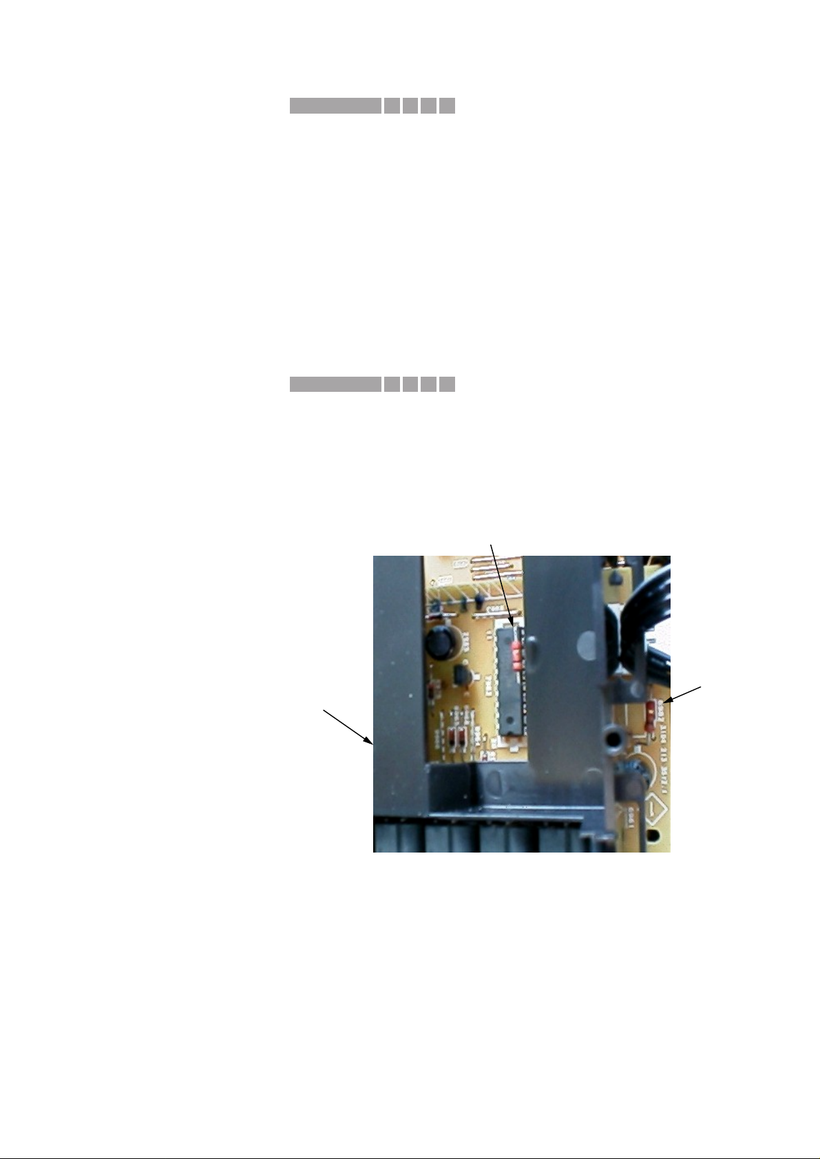
CURE : Safety resistors 3986 and 3998 on the S-VHS Video Selector Board
are mounted too close to the Tuner plastic holder frame.
In order to solve the problem, bend resistor 3986 approx. 40° towards
diode 6982 and bend resistor 3998 approx. 40° towards IC7962.
IMPORTANT: It is essential to check all sets brought in for repair
and to carry out above modification if required !!
REMARKS : The modification has been implemented in production from week
0131 onwards.
R3998
R3986
Tuner plastic
holder frame
F611IRIS CODE
X252IRIS CODE
Service Newsletter 2001 – BCU Audio 3/5
Page 16

04.10 TYPENUMBER(S): FW-C55, FW-C58, FW-C71, FW-C72, FW-C380, FW-M55, FW-V28,
FW-V55
SYMPTOM :
The set reacts on other Philips TV remote controls triggering
unwanted response.
CURE : The problem can be resolved by upgrading the Front Board
microprocessor software version.
The new microprocessors are available as follows:
pos. codenumber version typenumber(s)
–––––––––––––––––––––––––––––––––––––––––––––––––––––––
7401 9965 000 06155 11 FW-V28
7400 9965 000 10408 18 FW-C380
7400 9965 000 08007 18 FW-V55, FW-M55
7400 9965 000 10560 15 FW-C55, FW-C58, FW-C71, FW-C72
REMARKS : For solution of similar problems on other typenumbers see Ser vice
Newsletter SNL2001.01.30 resp.SNL2001.03.14.
04.11 TYPENUMBER(S): FW-C550, FW-C780
SYMPTOM :
1. Intermittent headphone noise.
2. Noise is audible in the AUX or RADIO channel from Volume Level 1
to Maximum.The noise level var ies with the Display illumination
(option NORMAL, MODE 1, MODE 2, MODE 3). An oscilloscope
connected to the speakers shows a frequency of 187Hz.
CURE : The problem is caused by glitches on the LPC line and can be
resolved by the following modification:
• Change 2570 from 47µF to 220µF (4822 124 12052) on the Front
Display Board.
• Change 3279 from 10kΩ to 47kΩ (4822 116 83884) on the L/R
Amplifier & Supply Board (MMPWR 100W Module).
REMARKS :
04.12 TYPENUMBER(S): FW-C83, FW-C85, FW-C90, FW-P88
INFORMATION : 1) To improve Reverse Record on tape 2, resistor 3379 on the Front
Board has been changed to 33Ω 5% 0,5W (4822 116 52191).
2) To improve CD sound distortion (for FW-C85/21/21M/30/37 and
FW-P88/37 only), the following resistors have been changed on the
AF8 Board:
• 3513 changed to 10kΩ 1% 0,1W (4822 117 10833)
• 3514 changed to 10kΩ 1% 0,1W (4822 117 10833)
• 3515 changed to 4,7kΩ 5% 0,1W (4822 051 20472)
• 3516 changed to 4,7kΩ 5% 0,1W (4822 051 20472)
REMARKS :
0452IRIS CODE
X511IRIS CODE
Service Newsletter 2001 – BCU Audio 4/5
Page 17

04.13 TYPENUMBER(S): MZ7/22, MZ7/34
INFORMATION : Correction to the Service Manual, schematic diagram and partslist
Front Board.The codenumber of the RDS demodulator IC 7403
should read:
7403 9352 679 67118 SAA6579T/V1/M4
REMARKS :
04.14 TYPENUMBER(S): SA100, SA101, SA107, SA125, SA126
INFORMATION : If the CD-ROM with the RealJukebox software has been lost or if
customers are using the operating system Windows ME, they can
download the most recent version of the free RealJukebox 2 Basic
software from RealNetworks at the following URL:
http://proforma.real.com/real/jukebox/jukebox.html?src=010709realho
me_1,010320rjbchoice_1&dc=816815814
REMARKS : The filesize of the full suite is about 8.7MB and the download will take
about 40 minutes with a 56k modem.
Service Newsletter 2001 – BCU Audio 5/5
Page 18
Service Newsletter 2001 – BCU Audio 1/8
For internal use only PHILIPS
ISSUE SNL2001.03 (01-07-09)
Published by:
Service Depar tment Audio
BUSINESS CREATION UNIT AUDIO
03.01 TYPENUMBER(S): AX2000, AX2001, AX2002, AX2003, AX2011, AX5000, AX5001,
AX5002, AX5003, AX5004, AX5006, AX5011, AX5012, AX5013,
AX5014, AX5015, AX5016, AX5017, AX5018, AX5019
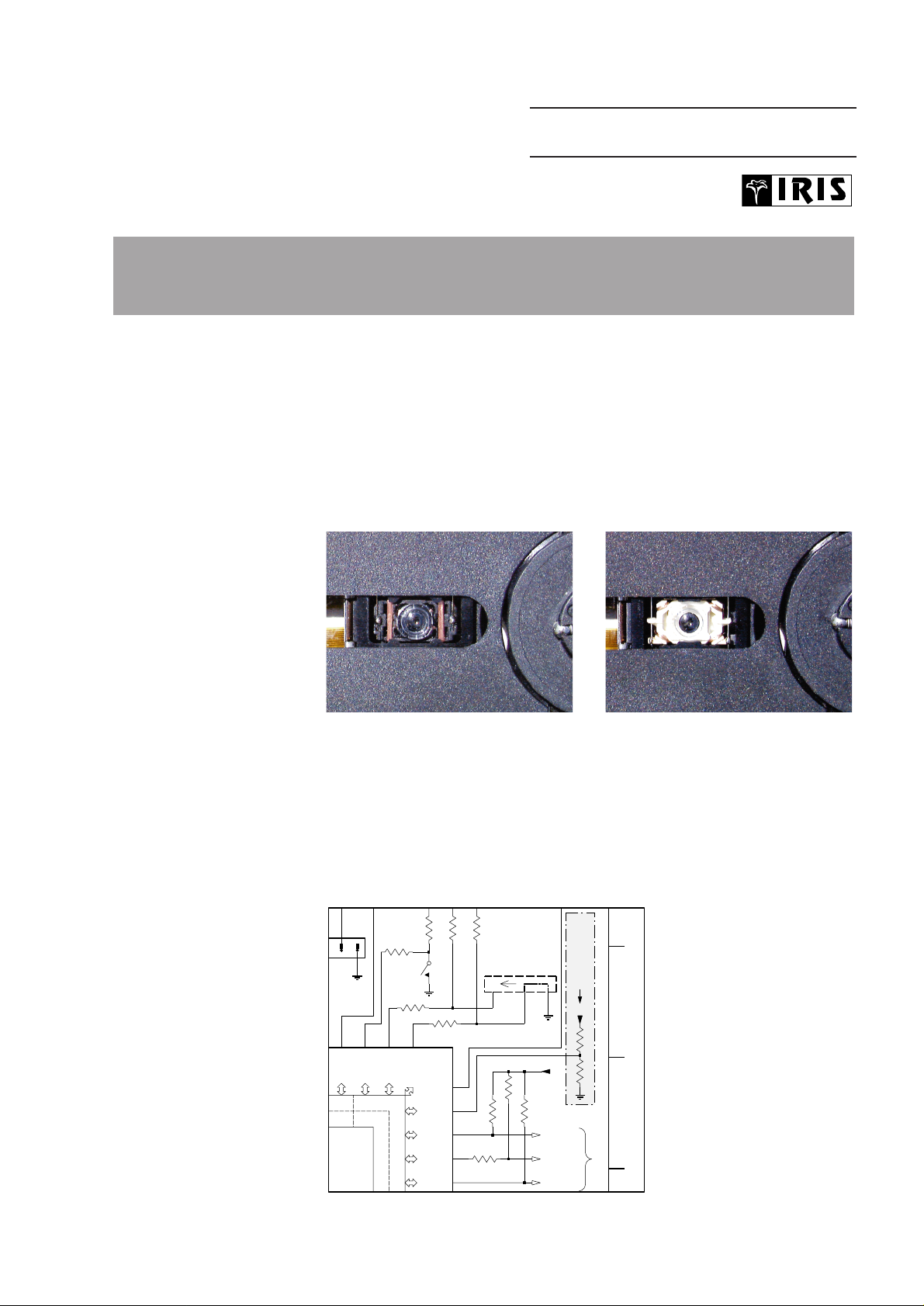
INFORMATION : Above mentioned typenumbers are produced with different CD-drives:
DA23LPH and DA23LNPH. The dr ives can be identified by the color
of the lens holder:
DA23LPH – black lens holder DA23LNPH – white lens holder
DA23LPH is no longer available as service sparepar t and has been
standardized to the newer DA23LNPH – 3103 309 05320.
Attention when replacing DA23LPH by DA23LNPH !
The new drive requires different software parameters and will not
work properly without the following hardware modification:
1. Remove pull-down resistor 3419L
2. Add pull-up resistor 3418LN
REMARKS :
P54
7400
SEG19
LCD - DRIVER
I/O PORT P5
P50
SEG23
P51
SEG22
P52
SEG21
P53
SEG20
SEG18
P70
SEG15
P57
SEG16
P56
SEG17
P55
B
C
to AUDIO-PART
LNL
B
C
2K7
3420
3401
220K
ESD
2
1
4K7
3416
1K
3404
36
28
29
30
31
32
333435
1401
SPPB51
0R
3418
1402
ESD-11H130
HOLD/RESUME
123 4
10K
3415
1K
3405
10K
3417
0R
3419
220K
3402
220K
CD-DRIVE DA23
VERSION SELECT
3403
ESD
DOOR
SWITCH
3406
1K
ESD
+2.6V
DBB_STEP
DBB_ON
+2.6V
chg_on
LF_POW
SERVICE NEWSLETTER
Page 19

03.02 TYPENUMBER(S): AZ1008, AZ1011, AZ1012
INFORMATION : In course of production, following changes have been implemented in
order to speed-up reading of TOC for some critical discs.
3832 changed from 6.8kΩ to 18kΩ (4822 117 10965)
2826 changed from 680pF to 1.5nF (4822 126 14247)
2864 changed from 27pF to 15pF (4822 126 13486)
REMARKS : The modification has been implemented in production from week
0122 onwards.
03.03 TYPENUMBER(S): AZ1008, AZ1011, AZ1012
SYMPTOM :
Cannot read CD.
CURE : The CD Door Switch (item 101) is not mounted properly. It cannot be
activated by the gear arm of CD Door (item 48).
Following countermeasures have been initiated:
1. Fixture in soldering process to ensure Door Switch is mounted
properly on the printed board.
2.Thickness of gear arm on CD Door increased to ensure enough
surface to activate the switch.
REMARKS : The modified parts have been implemented in production from week
0109 onwards.
03.04 TYPENUMBER(S): AZ1018
INFORMATION : In course of production, following changes have been implemented in
order to improve the problem “low recording level”.
3363 and 3364 changed from 10kΩ to 18kΩ (4822 117 10965)
REMARKS : The modification has been implemented in production from week
0114 onwards.
03.05 TYPENUMBER(S): AZ1018
INFORMATION : The procedure how to change the tuning grid is not mentioned in the
Instruction Manual. Please refer to below description:
• Switch off the set (mode switch in TAPE/OFF position).
• To select 9kHz: Hold PLAY-PAUSE and SEARCH S depressed
while switching to Tuner mode.
• To select 10kHz: Hold PLAY-PAUSE and SEARCH T depressed
while switching to Tuner mode.
Note:This procedure will clear all preset stations.
REMARKS : From week 0122 onwards, an addendum sheet has been added to
the sets.
1172IRIS CODE
Service Newsletter 2001 – BCU Audio 2/8
Page 20

03.06 TYPENUMBER(S): AZ2760, AZ2765, AZ2785
INFORMATION : The procedure how to change the tuning grid is not mentioned in the
Instruction Manual. Please refer to below description:
• Select Tuner mode and switch off the set.
• To select 9kHz: Hold BAND and SEARCH O depressed while
switching Power On.
• To select 10kHz: Hold BAND and SEARCH P depressed while
switching Power On.
Note:This procedure will clear all preset stations.
REMARKS : From week 0122 onwards, an addendum sheet has been added to
the sets.
03.07 TYPENUMBER(S): CDR570, CDR770, CDR771, CDR775, CDR776, CDR778
INFORMATION : In course of production, the Power Supply Unit “PSU CDR3 ECO” has
been modified:
6230 changed to BYV28-400 (4822 130 11415)
3113 changed to 1kΩ (4822 051 10102)
2253 added 4.7nF (2020 558 90449)
For reference see Service Infor mation A00-254.
Above changes have been implemented in course of production.
Manually adapted PSU’s are stamped “OP02”.
New modified produced PSU’s are stamped “OP03”.
Adapted PSU’s and new PSU’s will carry the following 12NC:
EURO : 3122 427 2200.5
USA : 3122 427 2201.5
WR : 3122 427 2202.5
Change code and 12NC are printed on a sticker which is placed on
capacitor 2121.
REMARKS : It is recommended to check respectively exchange above mentioned
components in all sets brought in for repair.
Service Newsletter 2001 – BCU Audio 3/8
Page 21
03.08 TYPENUMBER(S): CDR570, CDR770, CDR771, CDR775, CDR776, CDR778
SYMPTOM :
a) Set switches off when the mains cord is moved
b) No function
c) Set switches off intermittently
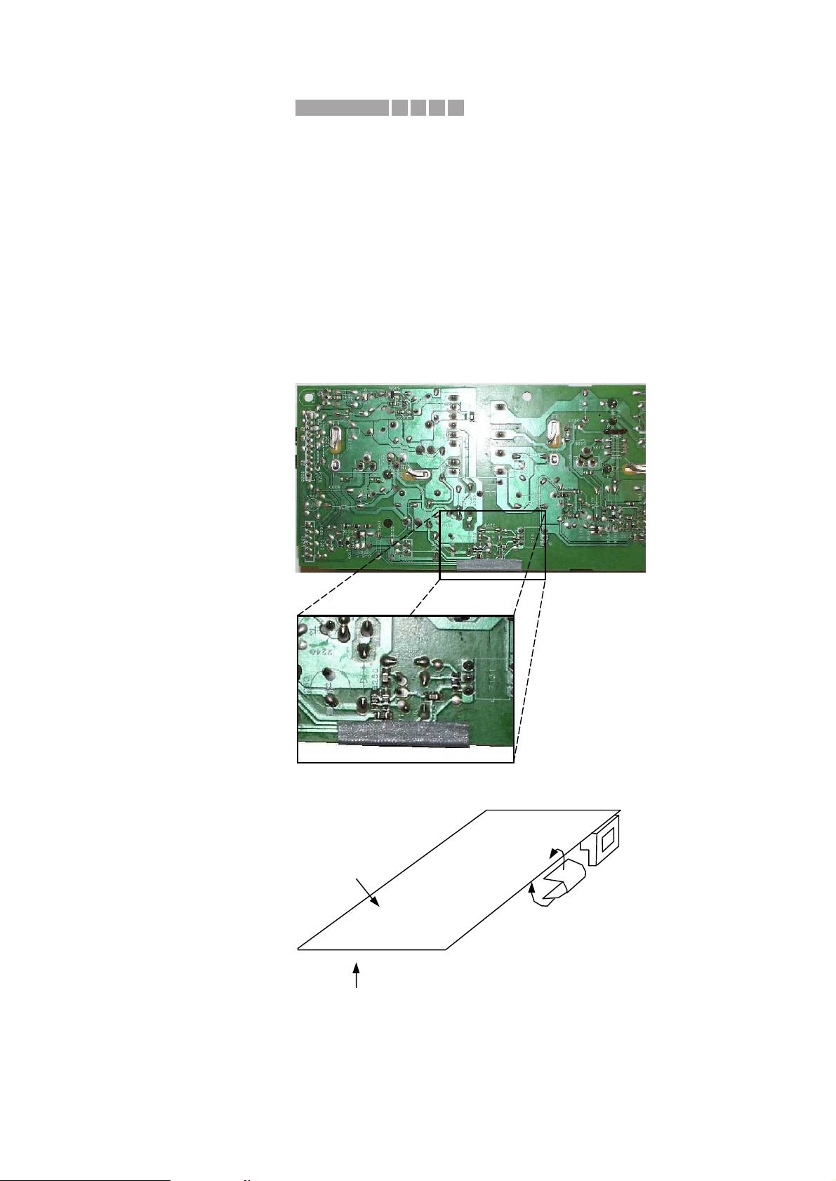
CURE : The copper tracks on the soldering side of the Power Supply Unit
“PSU CDR3 ECO” run too close to the edge of the printed circuit
board.This may cause
• a mechanical disruption of the copper tracks or
• a short-circuit to the metal backplate which in turn damages resistor
3201.
To solve this problem it is advised to fix a 2.5 cm piece of insulating
tape (i.e.TESA 4657, width = 1 cm) to the edge of the printed circuit
board as shown in pictures below.
1.
Bottom side
printed board
Component side
printed board
2.
0112IRIS CODE
Service Newsletter 2001 – BCU Audio 4/8
Page 22

REMARKS : The insulating tape has been implemented in production from week
0105 onwards. It is recommended to check all sets brought in for
repair.
The modification is mandatory for all PSU’s produced between week
0031 till 0105 with the following 12NC:
EURO : 3122 427 2200.1, .2, .3, .5
USA : 3122 427 2201.1, .2, .3, .5
WR : 3122 427 2202.1, .2, .3, .5
Change code and 12NC are printed on a sticker which is placed on
capacitor 2121.
03.09 TYPENUMBER(S): CDR570, CDR770, CDR771, CDR775, CDR776, CDR778
SYMPTOM :
Remote Control does not work properly or works intermittently.
CURE : Add a 100µF capacitor (4822 124 41584) on position 2213 of the
Power Supply Unit “PSU CDR3 ECO”.
For reference see Service Infor mation A00-254.
REMARKS : 2213 has been implemented in course of production.
Manually adapted PSU’s are stamped “OP02”.
Modified new produced PSU’s are stamped “OP03”.
Adapted PSU’s and new PSU’s will carry the following 12NC:
EURO : 3122 427 2200.5
USA : 3122 427 2201.5
WR : 3122 427 2202.5
Change code and 12NC are printed on a sticker which is placed on
capacitor 2121.
03.10 TYPENUMBER(S): CDR785, CDR786
INFORMATION : Correction to the Service Manual, Electrical Partslist
The codenumber for the NTC resistor 3399 is missing:
3399 4822 117 12063 10kΩ NTC
REMARKS :
03.11 TYPENUMBER(S): ECO5, ECO6 Tuner Board
SYMPTOM :
Auto Search Mode does not function.Tuner does not stop at any
station.When the tuner is tuned manually to a strong transmitter it
does not switch to STEREO (DC voltage on pin 24 of the Radio IC
7101 is 4.8V instead of 2V).
CURE : Exchange capacitor 2141 100nF 10% 50V (4822 126 13838).
REMARKS :
2621IRIS CODE
1512IRIS CODE
Service Newsletter 2001 – BCU Audio 5/8
Page 23

03.12 TYPENUMBER(S): FW-R7, FW-R8, FW-R88
SYMPTOM :
The CDR Module does not work correctly with ComPair.
Known problems:
1. Download of a new software version does not function
2. “Dead module” after replacement
CURE : 1.When the CDR Module is supplied by the Power Supply Unit of the
set, always make sure that
• the set is switched to CDR-mode and
• the Front-, AF-, Power L/R- and Supply CDr/w Boards are
connected properly.
This is necessary because the +5V supply for the CDR Module is
controlled by the Front-µP.Via IIC-Bus and IIC-shift register
(located on AF-Board) the CDR_ON signal is generated and via
Power L/R Board connected to Supply CDr/w Board.
2. Check solder connections of DASP IC.
Past experience has shown that most communication errors are
caused by weak solder connections of the DASP IC (item 7701).
REMARKS : After download of a new software version also look to the final
message that download was done successfully!
03.13 TYPENUMBER(S): FW-V220, FW-V320 and FW-V720
SYMPTOM :
No music, only noise is audible during MP3 playback.
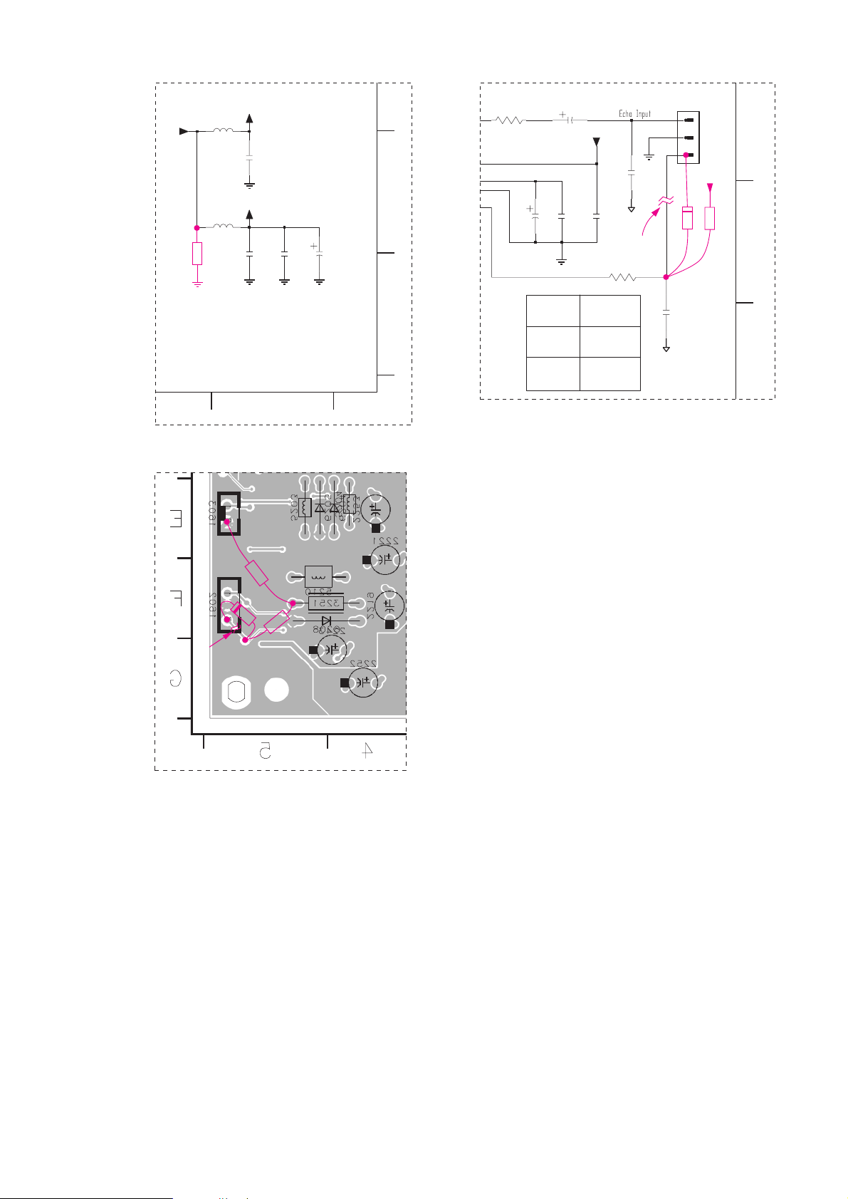
CURE : Due to residual voltage, the MPEG board does not get a proper reset.
The problem can be resolved by the following rework
(see drawings on next page):
1. Cut a copper track
2. Add a resistor 1kΩ (4822 050 21002) across +5V and ground
3. Add a resistor 10kΩ (4822 050 21003)
4. Add diode 1N4148 (4822 130 30621)
2451IRIS CODE
1811IRIS CODE
Service Newsletter 2001 – BCU Audio 6/8
Page 24
Portion of Circuit on page 8-7 Portion of Circuit on page 8-8
Portion of Layout on page 8-6, Copper Shielding side
REMARKS :
10k
1k
Cut
Copper
track
1N4148
&
C
D
E
MIC_DET
&
MIC_DET
Echo Function
Enable
Disable
Low
220R3244
High
1
2
3
1602
EH-B
2220
100n
100p
2261
2219
47u
AGND
AGND
100n
2218
47u
2217
VAA
3245 1K
2265
100p
+5V
Cut Copper
track
10k
1N4148
E
F
9
5V
5V
5207
100n
2201
5213
100u
2258
2210
100n
100n
2206
+5V
VCC7
VCC8
3139 118 54470 ...88170 sh1 ... 3448 pt 1 dd wk107
1k
Service Newsletter 2001 – BCU Audio 7/8
Page 25

03.14 TYPENUMBER(S): MC-50, MC-70
SYMPTOM :
The set reacts on Philips TV remote controls.
In worst case it switches to Service Test mode.
CURE : The problem is solved with new microprocessor software version 20.
The new microprocessor (item 7102 on Front Display Board) is
available with codenumber 9965 000 09493.
REMARKS : Check the microprocessor software version before replacement.
If the existing software is version 18, additional hardware adaptations
are required. See below 03.15, step 3a for details.
03.15 TYPENUMBER(S): MC-50, MC-70
SYMPTOM :
The 3-Disc Tray Changer “3DTC” is jammed and cannot be released
by a reset (disconnect/reconnect mains).
CURE : 1) Check and repair the 3DTC mechanism as necessary
2) Check the software version of the existing microprocessor 7102
3a) For software version 18 do the following:
F
ront Display Board
- replace 7102 with new microprocessor (9965 000 09493)
- change resistors 3209, 3210, 3211 to 220Ω (4822 051 30221)
CD Board
- change resistor 3783 to 2.7kΩ (4822 051 30272)
- change resistor 3790 and 3791 to 3.3kΩ (4822 051 30332)
3b) For software version 19 do the following:
Front Display Board
- replace 7102 with new microprocessor (9965 000 09493)
REMARKS :
X161IRIS CODE
X511IRIS CODE
Service Newsletter 2001 – BCU Audio 8/8
Page 26

For internal use only PHILIPS
ISSUE SNL2001.02 (01-05-16)
Published by:
Service Depar tment Audio
BUSINESS CREATION UNIT AUDIO
02.01 TYPENUMBER(S): ACT7585
INFORMATION : Correction to Service Manual
CD-drive DA23LN (3103 309 05320) has been used instead of
DA23L (3103 309 05340).The new CD-drive requires the following
modification for proper detection of the drive version:
Add 3418 4822 051 30008 Chip Jumper 0603
Delete 3419
REMARKS :
02.02 TYPENUMBER(S): ACT7585
INFORMATION : Correction to the Service Manual, Partslist
Resistor 3869 should be 47Ω (4822 051 30479).
REMARKS :
02.03 TYPENUMBER(S): AZ1018
INFORMATION : In course of production, resistor 3452 has been changed from 2.7kΩ
to 4.7kΩ (4822 051 30472) to improve “LCD leakage”.
REMARKS :
02.04 TYPENUMBER(S): AZ1110, AZ1111, AZ1112, AZ1113, AZ1114, AZ1116, AZ1117,
AZ1118, AZ1119, AZ8084, AZ8085, AZ8086, AZ8087
SYMPTOM :
Set doesn’t work with some specific batteries due to inproper battery
contact.
CURE : The guiding rib in the battery compar tment has been modified.
REMARKS : Modified parts are used in production with production code
KZ010049136XXX from week 0049 onwards.
X112IRIS CODE
SERVICE NEWSLETTER
Service Newsletter 2001 – BCU Audio 1/6
Page 27

02.05 TYPENUMBER(S): AZ2020, AZ2025
INFORMATION : Correction to Service Manual, Mechanical Partslist
The codenumber of the Contact Plate (item 449) should read
3140 111 21320.
REMARKS :
02.06 TYPENUMBER(S): AZ2785
INFORMATION : Correction to Service Manual, Mechanical Partslist
Items 443 (Cass Keys A) and 444 (Cass Keys B) will be delivered
together as a service kit. The codenumber reads 9965 000 09156.
REMARKS :
02.07 TYPENUMBER(S): CD6660
INFORMATION : Correction to Service Manual, Wiring Diagram and Electrical Partslist
The item number of the Flexible Foil 8800 is incorrect. It should read
8000 4822 320 12178 Flexible Foil
REMARKS :
02.08 TYPENUMBER(S): CDR570, CDR600, CDR602, CDR770, CDR771, CDR775, CDR776,
CDR778, CDR785, CDR786, CDR930, CDR950, CDR951, FW-R7,
FW-R8, FW-R88
INFORMATION : In case the Optical Pickup Unit “OPU” (item 2) has to be replaced, it
is absolutely necessary to replace the axle (item 4) at the same
time. For reference see Exploded View CDM3800 on next page resp.
chapter 4.4 of 2nd line Service Manual CDR570,... 3104 125 40110.
Also gear rack (item #) has to be investigated for damages of its
teeth. As follows the instruction how to replace these parts.
1. Demounting
1.1. First demount loader CDL4009 and CDR-MainBoard as given in
Mechanical Instructions, chapter 4.1.
1.2. Now the OPU can be de-mounted. See chapter 4.4 (Exploded
View CDM3800)
1.3. Loosen 2 screws (6 and 8)
1.4.Take away the old OPU 2 with its axle 4 and gear rack assy #
by lifting it up at that released side and then shift it from it's other
axle 3.
1.5.Take care of spring ™. It can be reused for the new OPU.
1.6. Remove gear rack # from the OPU by removing axle 4. If the
gear rack is not damaged it can be reused for the new OPU.
2. Mounting
2.1. Mount the new axle 4 through new OPU and gear rack #
2.2. Mount spring ™
2.3. Position the OPU under axle 3.Take care of spring ™.
2.4. Press the gear rack # in such a way that both rackteeth are in
line with each other.Interlock gear rack # with gear wheel @.
Service Newsletter 2001 – BCU Audio 2/6
Page 28
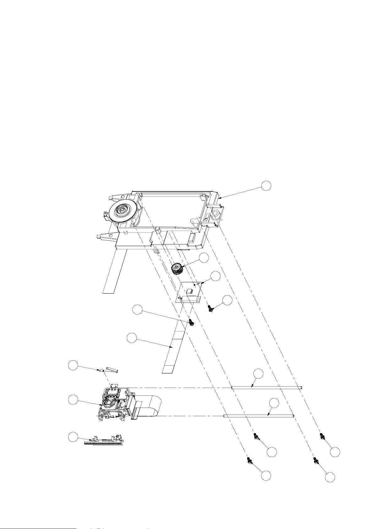
The tension on the gear-rack will reduce the offset of the
mechanical movement drastically.
2.5. Fasten axle 4 with 2 screws (6 and 8)
2.6. Now the OPU is mounted in the CDM.Write down the
parameters of the OPU for later adjustments.The parameters
represent the last five digits of the 12 NC, the 0.7mW value and
the 20mW value (i.e.13981;00735;02098).
2.7. Remount and reconnect the CDR-main-board and do not forget
to execute the adjustment procedure via ComPair in order to
match the CDR-main-board with the new OPU.
3. Adjustment
3.1. After replacement of the OPU it is absolutely necessary to star t
ComPair Adjustment procedure immediately. Follow the
instructions as given by ComPair.
REMARKS :
EXPLODED VIEW CDM3800
12
1
23
26
24
3
4
7
8
6
5
22
2
13
25
Service Newsletter 2001 – BCU Audio 3/6
Page 29

02.09 TYPENUMBER(S): ECO5, ECO6 Tuner Board
SYMPTOM :
After a few minutes of operation there is no sound audible although
the display shows still the correct tuning frequency.
When the tuner is switched off for some time the displayed frequency
will be completely wrong after switching on again.
CURE : The most probable reason is a leaky ceramic capacitor 2165
(resistance of a few hundred Ohm can be measured).
The defective capacitor causes a drop of Vref (1.5V instead of 2V at
pin 1 of IC7101) along with a drop of the internal stabilized voltages
VstabA and VstabB (0.8V instead of 1.4V at pins 34 and 38).
As a result IC7101 will not work anymore.
The problem can be solved by replacing capacitor 2165.
REMARKS : Check also ceramic capacitors 2139 and 2152.
02.10 TYPENUMBER(S): FW-R7, FW-R8, FW-R88
INFORMATION : Correction to the Service Manual, Mechanical Partslist chapter 12-3
The codenumber for Rubber Foot pos. 271 should read
3104 217 72032.
REMARKS :
02.11 TYPENUMBER(S): FW-V220, FW-V320
INFORMATION : Correction to the Service Manual, Circuit diagram and Partslist
Combi Board
2405 Deleted
3456 Deleted
3681 4822 116 52276 3.3kΩ 5% 0,5W
3682 4822 116 52276 3.3kΩ 5% 0,5W
REMARKS :
02.12 TYPENUMBER(S): MC-10, MC118
SYMPTOM :
Sharp voice is audible on recording.
CURE : Change resistor 3732 from 10Ω to 15Ω (4822 116 82182).
REMARKS : Modification has been implemented in production from week 0101
onwards.
2451IRIS CODE
0123IRIS CODE
Service Newsletter 2001 – BCU Audio 4/6
Page 30
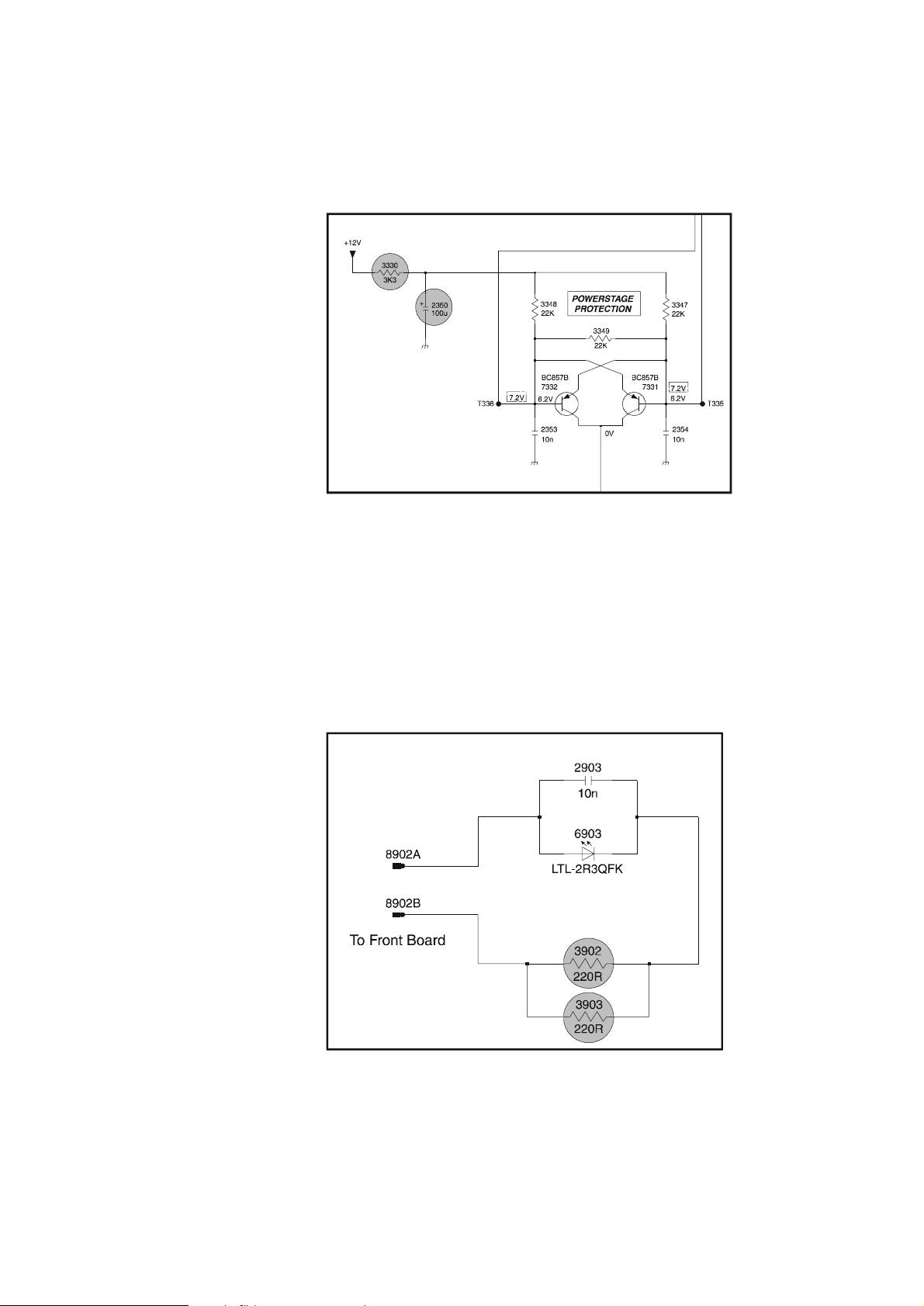
02.13 TYPENUMBER(S): MC-10, MC-20, MC-30, MC118, MC148
INFORMATION : In course of production, the following components have been added
on the Combi Board to improve power muting:
2350 4822 124 40207 100µF
3330 4822 116 52269 3.3kΩ
REMARKS :
02.14 TYPENUMBER(S): MC-30
INFORMATION : Backlight board: In course of production, resistor 3903 has been
added in parallel to resistor 3902 to prevent overheating.
The value for both resistors is 220Ω, available with codenumber
4822 117 11503.
REMARKS :
Service Newsletter 2001 – BCU Audio 5/6
Page 31

02.15 TYPENUMBER(S): MC-30/37
INFORMATION : Correction to Service Manual, Mechanical Partslist
The codenumber of the Mains Cord Relief for /37 (item 439) should
read 3140 113 22100.
REMARKS :
02.16 TYPENUMBER(S): MC-45, MC-50
INFORMATION : Correction to the Service Manual, Circuit diagram and Partslist
Front Control Board
6300 4822 130 11589 LTL-1CHAE
6301 4822 130 11589 LTL-1CHAE
6302 4822 130 11589 LTL-1CHAE
6303 4822 130 11589 LTL-1CHAE
6400 9322 167 73676 LTL-4221NLC-KA
REMARKS :
02.17 TYPENUMBER(S): MC-70
INFORMATION : Correction to the Service Manual, Circuit diagram and Partslist
Front Control Board
6400 9322 167 73676 LTL-4221NLC-KA
Front Display Board
3201 4822 052 10228 2.2Ω 5% 0,33W
3202 4822 052 10228 2.2Ω 5% 0,33W
Mechanical & Accessories – Main Unit
141 3139 113 27010 Cut Sheet Display Blue
1131 3139 110 35560 Flex Cable 19pin 18cm AD folded
1133 3139 110 35570 Flex Cable 9pin 10cm AD
1138 3139 110 35520 Flex Cable 19pin 10cm AD
REMARKS :
02.18 TYPENUMBER(S): MC118, MC148
INFORMATION : It might happen that sets are returned with broken CD Door (item
442) and CD Tray (item 434).The broken area is around the holder
for CD Door Spring. From production week 0112 onwards the parts
have been strengthened by increasing the wall thickness of the spring
holder and adding supporting ribs.
REMARKS : Modified parts are used in production from week 0112 onwards.
Service Newsletter 2001 – BCU Audio 6/6
Page 32

For internal use only PHILIPS
ISSUE SNL2001.01 (01-03-20)
Published by:
Service Depar tment Audio
BUSINESS CREATION UNIT AUDIO
01.01 TYPENUMBER(S): ACT7583
SYMPTOM :
CD does not stop when door is opened.
CURE : Change capacitor 2962 from 470pF to 1nF (5322 126 11578).
REMARKS : The modification has been implemented in production from week
0048 onwards.
01.02 TYPENUMBER(S): AQ4150
INFORMATION : Additional information to Service Newsletter SNL2000.03.01.
The problem of poor recording from FM can further be improved by
adding a capacitor of 0,47µF between R2 and pin 13 of IC1
(TDA5710).
REMARKS :
01.03 TYPENUMBER(S): AS680C, AS681C, FW72C, FW346C, FW350C, FW356C, FW358C,
FW359C, FW388V, FW390C,FW391C, FW396C, FW399V, FW530C,
FW535C, FW538, FW545C/21/22/37, FW548C/21, FW548V,
FW550C, FW555C, FW570C, FW575C, FW585C,
FW595C/21/21M/30, FW765P, FW768P, FW775P, FW795W,
FW798W, FW830C/21/37, FW870C/21, FW878C/21/21M,
FW890P/21/30/37, FW898W/21, FW910
INFORMATION : Service Manual, Partslist
The Cam Gear (pos 25) of the Tape mechanism has been added as
service spare par t. The codenumbers read:
9965 000 06443 for Mechanism B (Record/Playback)
9965 000 08069 for Mechanism A (Play only)
REMARKS :
X262IRIS CODE
SERVICE NEWSLETTER
Service Newsletter 2001 – BCU Audio 1/16
Page 33

01.04 TYPENUMBER(S): AZ1030
INFORMATION : Correction to Service Information A00-558 (3140 785 22460):
Actually, IC LA6531 (4822 209 32636) is used instead of LA6530.
LA6531 is functionally identical to LA6530.
REMARKS :
01.05 TYPENUMBER(S): AZ1040, AZ1045
INFORMATION : Correction to the Service Manual, Mechanical Partslist:
The CD Door of AZ1045 is different to AZ1040.
The correct code numbers are:
3140 114 32950 CD Door (AZ1040)
3140 114 32930 CD Door (AZ1045)
REMARKS :
01.06 TYPENUMBER(S): AZ1550, AZ1560, AZ1564, AZ1565
INFORMATION : It might happen that sets are returned with broken Front Cabinet.The
broken area is around the holder for Cassette Door Spring.From
production week 0108 onwards the part has been strengthened by
increasing the wall thickness of the holder from 1mm to 2.5mm.The
improved Front Cabinet assembly can be ordered at LO-PCS with
following code numbers:
AZ1550 : item 414 3140 117 58840
AZ1560 : item 417 3140 117 58580
AZ1564 : item 417 3140 117 58580
AZ1565 : item 417 3140 117 58580
REMARKS : The modified parts are used in production with production code
KT010108085xxx from week 0108 onwards.
01.07 TYPENUMBER(S): AZ1602, AZ1605
SYMPTOM :
Hiss is audible on recordings.
CURE : Change resistor 3787 from 33Ω to 100Ω (4822 116 52175).
REMARKS : The modification has been implemented in production from week
0102 onwards.
2451IRIS CODE
Service Newsletter 2001 – BCU Audio 2/16
Page 34
01.08 TYPENUMBER(S): AZ2020, AZ2025
INFORMATION : It might happen that sets are returned with broken CD Door (item
441) and Top Cabinet (item 503). The broken area is around the
holder for CD Door Spring. From production week 0106 onwards the
parts have been strengthened by adding ribs and increasing the wall
thickness of the holder. The improved parts can be ordered at LOPCS with following code numbers.
AZ2020 : item 441 3140 117 59050 CD Door Assembly
AZ2020 : item 503 3140 117 59150 Top Cabinet Assembly
AZ2025 : item 441 3140 117 59130 CD Door Assembly
AZ2025 : item 503 3140 117 59150 Top Cabinet Assembly
REMARKS : The modified parts are used in production with production code
KT010106020xxx from week 0106 onwards.
01.09 TYPENUMBER(S): CDR570, CDR770, CDR775, CDR776, CDR785, CDR786, CDR930,
CDR950, CDR951, FW-R7, FW-R8
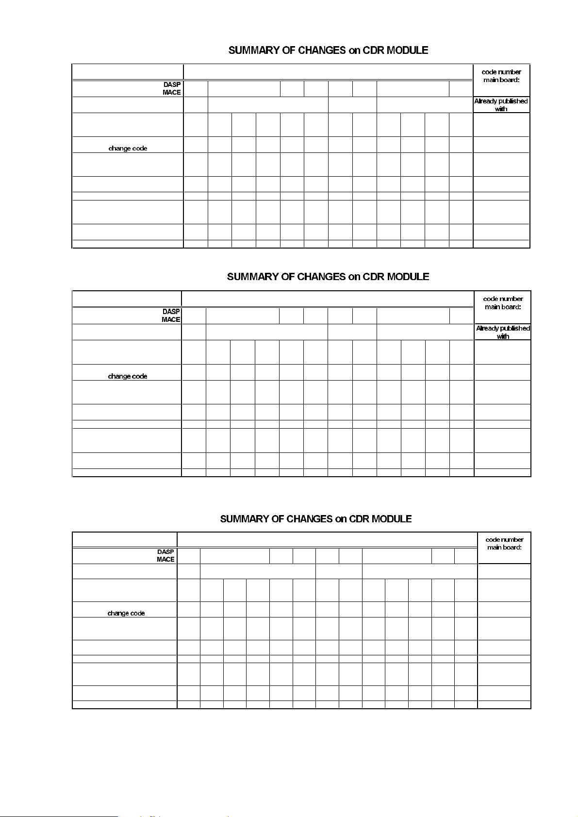
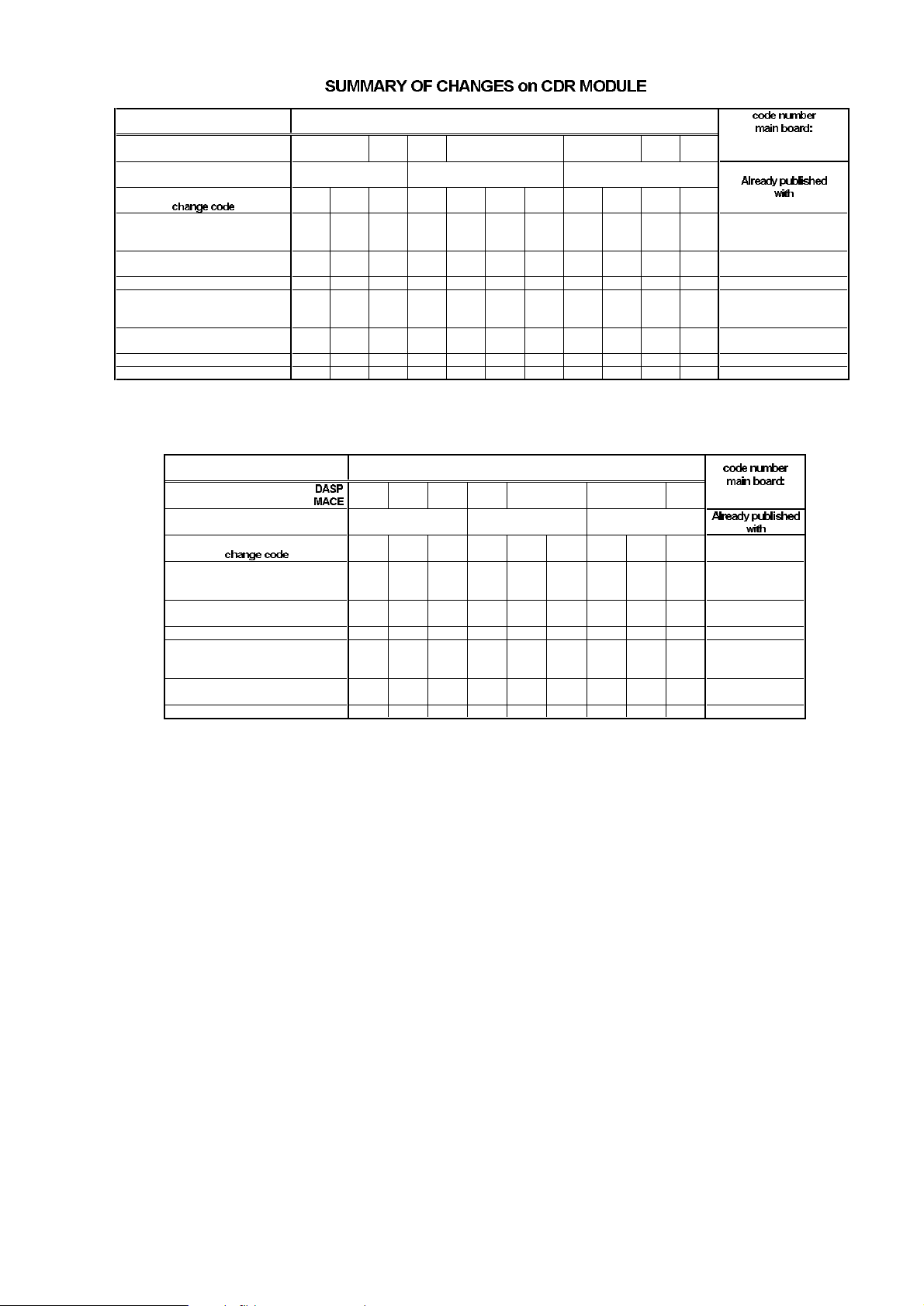
INFORMATION : Summary of hardware and software modifications to the CDR
Main Board.
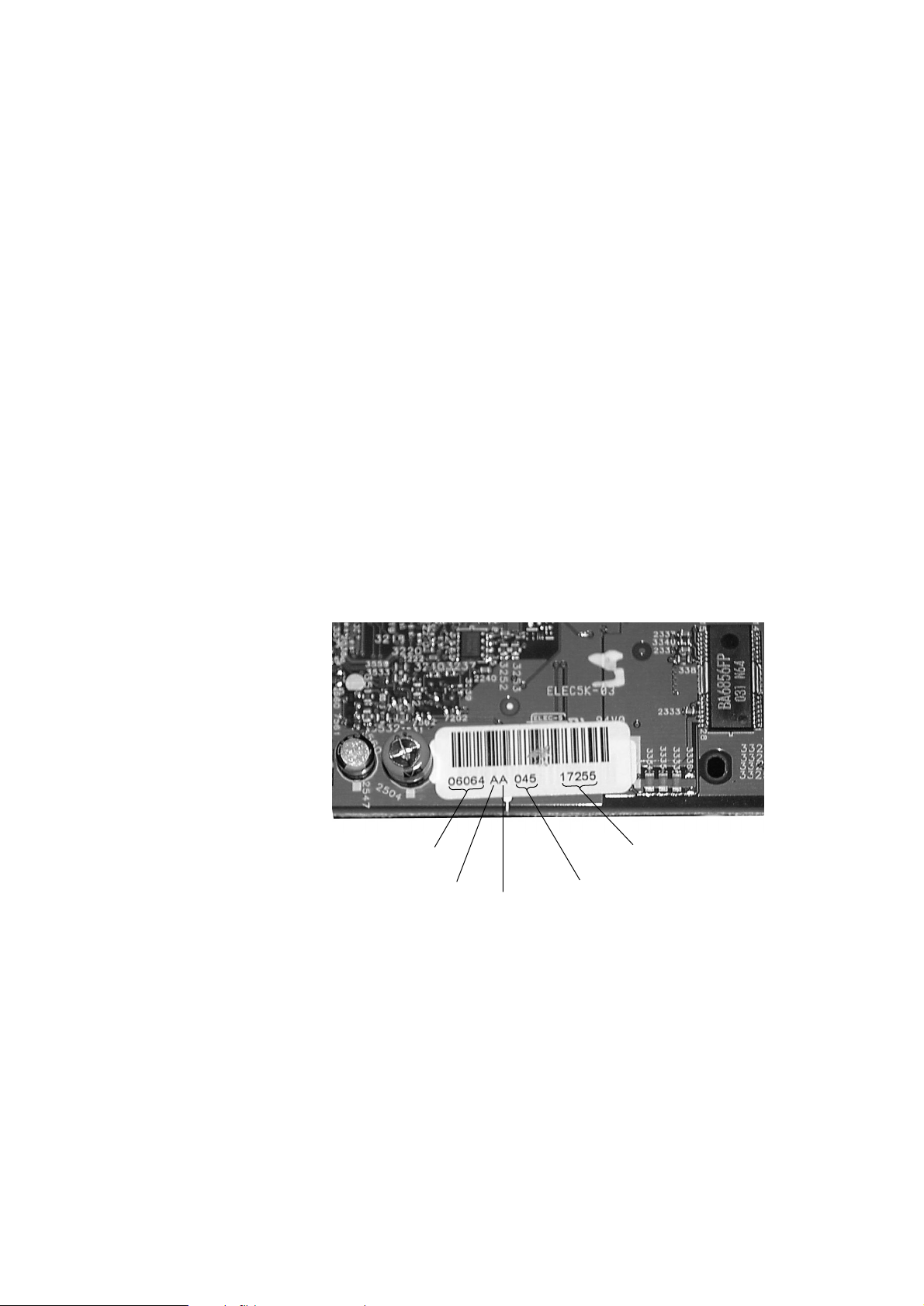
In the following tables there is given reference to “main board labelled
with change code”.This label can be found on top at the front side of
the main board.
When “AA” is printed (as shown in picture above) this means that the
main board has once been upgraded before assembling in the set.
In this case the status has to be determined by reading out the
software versions via service testprogram - the procedure is
described in the service manual of the relevant set - or can be found
on a sticker on Flash ROM 7208.
Note: A clear determination of the status can best be given by
reading out the software versions!
“Y” means that software has to be/can be upgraded
or mentioned hardware change has to be done.
Empty fields mean that changes are already implemented in boards
with corresponding label.
last 5 digits of
code number
change code
production line
production week
serial number
Service Newsletter 2001 – BCU Audio 3/16
Page 35
software version
1.04 &
91.48
1.34 &
91.80
1.43 &
91.91
1.47 &
91.96
1.51 &
92.01
1.55 &
92.11
1.56 &
92.11
Y SNL 2000.07.08
<FGH I JKLMNOPT
Y Y Y Y Y Y Y Y Y Y Y SNL 2000.07.08
Y
SNL 2000.03.09
Y Y Y Y Y Y Y Y SNL 2000.07.13
YYYYYYYYYYY
SNL 2000.07.10
see also
SNL 2000.07.09
Y Y Y Y Y Y Y Y Y SNL 2000.04.02
Y Y Y Y Y Y Y Y SNL 2000.07.12
3104 128 0586x
24sept ’99 03apr ’00
1.54&
92.08
CDR775
28sept ’00NAM-File
mainboard labelled with
update SW to 1.56 & 92.11 possible?
--> adjust via COMPAIR 1.6
change 2322 from 3.3nF to 1.5nF
Print layout A2 or A3 to be replaced by
a new main board 3104 128 05860
1.23 &
91.63
change 2335 from 10nF to 47nF &
3337 from 68kOhm to 56kOhm
add resistor 3535, 27Ohm
replace 2725, 2726, 2727 by
100n 50V
change 3411 and 3439 from 4.7Ohm
to coil 50µH
TYPENUMBER
Already published
with
software version
1.04 &
91.48
1.34 &
91.80
1.43 &
91.91
1.47 &
91.96
1.51 &
92.01
1.56 &
92.11
Y SNL 2000.07.08
<FGHI J KLMNOS
YYYYYYYYYY SNL 2000.07.08
Y
SNL 2000.03.09
Y Y Y Y Y Y Y SNL 2000.07.13
YYYYYYYYYY
SNL 2000.07.10
see also
SNL 2000.07.09
YYYYYYYY SNL 2000.04.02
Y Y Y Y Y Y Y SNL 2000.07.12
28sept ’00
3104 128 0585x
24sept ’99 03apr ’00
1.54&
92.08
NAM-File
mainboard labelled with
update SW to 1.56 & 92.11 possible?
--> adjust via COMPAIR 1.6
CDR770
Print layout A2 or A3 to be replaced by
a new main board 3104 128 05850
1.23 &
91.63
change 2335 from 10nF to 47nF &
3337 from 68kOhm to 56kOhm
add resistor 3535, 27Ohm
replace 2725, 2726, 2727 by
100n 50V
to coil 50µH
TYPENUMBER
software version
1.04 &
91.48
1.34 &
91.80
1.43 &
91.91
1.47 &
91.96
1.51 &
92.01
1.56 &
92.11
Y SNL 2000.07.08
<FGH I JKLMNOS
Y Y Y Y Y Y Y Y Y Y SNL 2000.07.08
Y
SNL 2000.03.09
Y Y Y Y Y Y Y SNL 2000.07.13
YYYYYYYYYY
SNL 2000.07.10
see also
SNL 2000.07.09
Y Y Y Y Y Y Y Y SNL 2000.04.02
Y Y Y Y Y Y Y SNL 2000.07.12
28sept ’00
3104 128 0584x
24sept ’99 03apr ’00
1.54&
92.08
NAM-File
mainboard labelled with
update SW to 1.56 & 92.11 possible?
--> adjust via COMPAIR 1.6
CDR570, CDR930
Print layout A2 or A3 to be replaced by
a new main board 3104 128 05840
1.23 &
91.63
change 2335 from 10nF to 47nF &
3337 from 68kOhm to 56kOhm
add resistor 3535, 27Ohm
replace 2725, 2726, 2727 by
100n 50V
change 3411 and 3439 from 4.7Ohm to
coil 50µH
TYPENUMBER
Service Newsletter 2001 – BCU Audio 4/16
change 2322 from 3.3nF to 1.5nF
change 3411 and 3439 from 4.7Ohm
change 2322 from 3.3nF to 1.5nF
Page 36
Solved phenomena with the following software versions:
Version 1.23
• improvement and shortening startup procedure
• CD-sync start procedure improved
Version 1.34 (0.23 for CDR785 and Mini sets)
• further improving and shor tening star tup procedure
Version 1.43 (0.24 for CDR785 and Mini sets)
• does not start : display shows insert disc
• does not start : display shows OPC error
• does not start finalising / unfinalising
• extra track increments during analog and digital recording
• does not start erase
• does not start analog recording
• bad audio
• player in standby during recording or finalising
Version 1.47 (0.25 for CDR785 and Mini sets)
• does not start: set in hangup
• in hangup after finalising / unfinalising
software version
1.23 &
91.63
1.34 &
91.80
1.43 &
91.91
1.47 &
91.96
1.56 &
92.11
ABCDEFGHK
Y Y Y Y Y Y Y Y SNL 2000.07.08
Y
SNL 2000.03.09
Y Y Y Y Y SNL 2000.07.13
YYYYYYY
SNL 2000.07.10
see also
SNL 2000.07.09
Y Y Y Y Y SNL 2000.04.02
Y Y Y Y Y SNL 2000.07.12
1.54&
92.09
28sept ’00
SUMMARY OF CHANGES on CDR MODULE
3104 128 0587x
24sept ’00
CDR950, CDR951
1.51 &
92.01
03apr ’00NAM-File
mainboard labelled with
update SW to 1.56 & 92.11 possible?
--> adjust via COMPAIR 1.6
change 2335 from 10nF to 47nF &
3337 from 68kOhm to 56kOhm
add resistor 3535, 27Ohm
replace 2725, 2726, 2727 by
100n 50V
change 3411 and 3439 from 4.7Ohm to
coil 50µH
TYPENUMBER
TYPENUMBER
software version
0.24 &
91.91
0.25 &
91.96
0.30 &
92.11
0.31 &
92.11
NAM-File
mainboard labelled with
<C D E F G H I J K L M
update SW to 0.31 & 92.11 possible?
--> adjust via COMPAIR 1.6
Y Y Y Y Y Y Y Y Y Y Newsletter 2000.07.08
change 2335 from 10nF to 47nF &
3337 from 68kOhm to 56kOhm
Y Newsletter 2000.03.09
add resistor 3535, 27Ohm Y Y Y Y Y Newsletter 2000.08.09
replace 2725, 2726, 2727 by
100n 50V
YYYYYYYY
Newsletter 2000.07.10
see also
Newsletter 2000.07.09
change 3411 and 3439 from 4.7Ohm
to coil 50µH
Y Y Y Y Y Y Newsletter 2000.04.02
add item 2721, 6.8kOhm Y Y Y Y Y Y Y Y
change 2322 from 3.3nF to 1.5nF Y Y Y Y Y Newsletter 2000.07.12
24sept '99 03apr '00 28sept '00
CDR785, CDR786, FW-R7, FW-R8
CDR Mini 3104 128 0659x
CDR78x 3104 128 0606x
0.23 &
91.80
0.26 &
92.01
0.29&
92.08
DASP
MACE
Service Newsletter 2001 – BCU Audio 5/16
change 2322 from 3.3nF to 1.5nF
Page 37

Version 1.51 (0.26 for CDR785 and Mini sets)
• does not recognize the Philips HR100 CDR disc
Version 1.54 (0.29 for CDR785 and Mini sets)
• does not recognize Philips Megalife Audio 100 CDR disc (produced
by MITSUI) and other brand CDR discs
Version 1.56 (0.31 for CDR785 and Mini sets)
• adaption for 2Mbit flash EPROM AM29LV160BB (used to cover
supply shortfall of original 1MBit type)
• communication with internal CD player improved (only valid for
double deck sets) → uniform software for all applications
REMARKS :
01.10 TYPENUMBER(S): CDR570, CDR770, CDR775, CDR930, CDR950
SYMPTOM :
Not reading/recording of Non-Philips branded CDR-discs respectively
Philips Megalife disc produced by Mitsui.
(for details concerning the MITSUI-discs see information in
SNL2000.07.14 respectively point 01.14 in this Service Newsletter)
CURE : The problem can be solved by applying the modifications as
mentioned in SNL2000.07.08 and with an update to the latest
software versions.The hardware modification which has to be
executed depends on the original SW version. Details are also given
in the
Summary of hardware and software modifications to the CDR
Main Board
, published with point 01.09 in this Service Newsletter.
• The Flash ROM software version of item 7208 (MACE) on the top
side (in socket) has been changed into version 92.11. Programmed
Flash ROM with SW-version 92.11 or higher can be ordered with
codenumber 3104 123 94850.
• The Flash ROM software version of item 7703 (DASP) on the top
side has been changed into version 1.56. Programmed Flash ROM
with SW-version 1.56 or higher can be ordered with codenumber
3104 123 85760.
REMARKS : After the update of both Flash ROMs, the module has to be re-
aligned with the improved COMPAIR-tool (release 1.6 or higher).
The CDR-alignment includes now beta adjustment via Test Disc 99
(TD99). After this modification and alignment all Digital Audio CDRdiscs can be applied (no longer restricted to only Philips brand).Test
Disc 99 is available with codenumber 7104 099 93132.
165CIRIS CODE
Service Newsletter 2001 – BCU Audio 6/16
Page 38

01.11 TYPENUMBER(S): CDR570, CDR770, CDR775, CDR930, CDR950, CDR951
SYMPTOM :
After switching on the set, the standby-LED will start blinking and the
display does not light up.
CURE : Delete item 2546 (Elcap 47µF 6,3V) on the mainboard.
REMARKS : The modification has been implemented in production from week
0048 onwards.
01.12 TYPENUMBER(S): CDR570, CDR770, CDR930
INFORMATION : When customers complain that the Remote Control does not work
this does not necessarily mean that it is defective.More often the
customer has simply selected the wrong source on the RC.
Especially sets with single CDR loader will not react at all when “CD”
has been pressed on the RC.
Therefore the customer has to be advised as follows:
1) Select the right source first → Press <CDR> button and try again.
2) Point the Remote Control directly to the CD recorder.
3) Check the batteries and replace if necessary.
REMARKS :
01.13 TYPENUMBER(S): CDR770, CDR771, CDR775
INFORMATION : Item 251-252 (foot) with codenumber 4822 462 42159 has been
changed from “MATT SILVER” into “GLOSSY SILVER”.
The new codenumber for the GLOSSY SILVER foot reads
4822 462 11174.
REMARKS : The modification has been implemented in production from week
0047 onwards.
01.14 TYPENUMBER(S): CDR785, CDR786, FW-R7, FW-R8
SYMPTOM :
Not reading/recording of Non-Philips branded CDR-discs respectively
Philips Megalife disc produced by Mitsui.
All returned discs, causing complaints on the CDR sets of the 3rd
generation have been investigated.This results in the following
conclusion:
The Philips Megalife disc has been produced by Ricoh and Mitsui.
Most of the problems have been found with discs produced by Mitsui.
How to recognize the production centre?
Ricoh : Made in USA printed on the jewel box.
Mitsui : Made in Europe printed on the jewel box.
165CIRIS CODE
A112IRIS CODE
Service Newsletter 2001 – BCU Audio 7/16
Page 39

Please note: Discs packed in a carton box(5pcs/carton) are marked
with made in USA.
Ricoh : Marked Audio HR100
Mitsui : Marked Audio 100
Ricoh : Serial number on inner circle consists of 4 character + 12
digits (e.g. ALXH 061099022143)
Mitsui : Serial number on inner circle consists of 12 digits
(e.g. 9287 2217 4953)
Note: It is not advised to apply the Mitsui disc in 3rd generation
CDR recorders up to software version 0.26.
CURE : This problem can be solved by applying hardware modifications and
with an update to the latest software version.The hardware
modification which has to be executed depends on the or iginal SW
version. Details are given in the
Summary of hardware and software
modifications to the CDR Main Board
, published with point 01.09 in
this Service Newsletter.
• The Flash ROM software version of item 7208 (MACE) on the top
side (in socket) has been changed into version 92.11. Programmed
Flash ROM with SW-version 92.11 or higher can be ordered with
codenumber 3104 123 94850.
• The Flash ROM software version of item 7703 (DASP) on the top
side has been changed into version 0.31. Programmed Flash ROM
with SW-version 0.31 or higher can be ordered with codenumber
3104 123 85810.
REMARKS : After the update of both Flash ROMs, the module has to be re-
aligned with the improved COMPAIR-tool (release 1.6 or higher).
The CDR-alignment includes now beta adjustment via Test Disc 99
(TD99). After this modification and alignment all Digital Audio CDRdiscs can be applied (no longer restricted to Philips brand only).
Test Disc 99 is available with codenumber 7104 099 93132.
01.15 TYPENUMBER(S): EXP101, EXP103
SYMPTOM :
Abnormal Noise is audible during playback.
CURE : Replace diode 6251 by a jumper (4822 051 20008).
REMARKS : The modification has been implemented in production from week
0049 onwards.
01.16 TYPENUMBER(S): FW-C1, FW-C99, FW-C100
INFORMATION : To solve CD lens knocking problem adapt the following:
a) change 2342 from 100µF to 47µF 25V (4822 124 40433)
b) replace 5501 2,2µH by a bare wire
REMARKS :
2451IRIS CODE
Service Newsletter 2001 – BCU Audio 8/16
Page 40
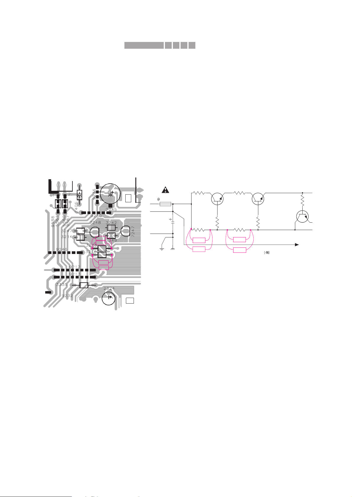
01.17 TYPENUMBER(S): FW-C1/21, FW-C10/21, FW-C100/21/21M/19
SYMPTOM :
The set functions normally with the following observation on the
Combi Board:
- Elcap 2225 4700µF / 16V becomes bloated.
- PC Board area below resistors 3246 and 3248 becomes blacken
with overheating sign.
CURE : The voltage across Elcap 2225 is close/higher than its rated voltage
and resistors 3246 and 3248 are overstressed.
The problem is resolved by the following modification:
1. Replace Elcap 2225 with 4700µF / 25V (4822 124 12012).
2. Replace resistors 3246 and 3248 by 3 pieces of 330Ω 1/6W
(4822 116 52219) each as follows:
• replace 3246 and 3248 by 330Ω 1/6W
• solder 4 resistors 330Ω 1/6W across 3246 and 3248 on the
copper side as shown.
REMARKS :
01.18 TYPENUMBER(S): FW-C3/37, FW-C30/37, FW-C35/37, FW-C38/37
INFORMATION : To reduce failures of Power Amplifier IC 7391 (AN7125):
change capacitor 2355 from 2,2nF to 560pF 50V (5322 116 80853).
REMARKS : The modification has been implemented in production from week
0045 onwards.
BC547B
7245
+C
Q
BC337-25
7248
32483246
3214
2225
4m7
4R7
1K
3252
9224
7247
3249
100R
BC337-25
4R7
3242
1206
100R
3247
AP
Portion of Combi Board,
componentside view
Portion of Power Supply Circuit
330R
330R
330R
330R
330R330R
330R
330R
330R
330R
/ 25V
X611IRIS CODE
Service Newsletter 2001 – BCU Audio 9/16
Page 41

01.19 TYPENUMBER(S): FW-C80, FW-C83, FW-C85, FW-P88
INFORMATION : Additional service par ts
The loudspeaker cord (3 meter length) is now available with service
code 4399 294 04131.
REMARKS :
01.20 TYPENUMBER(S): FW-C80, FW-C83, FW-C85, FW-P88, FW-C870, FW-P880
INFORMATION : wOOx Demo mode
When a wOOx Demo Disc is placed on the tray - CD pos.1, the
wOOx Demo mode is activated as soon as the TOC is read. In this
mode the tray is locked and the Open/Close button cannot be
activated anymore.
To exit the wOOx Demo mode, do the following:
1) Press the Standby button
2) Hold the wOOx button depressed until the CD tray opens.
REMARKS : On tray - CD pos.2 and 3 the disc will play normally without going into
locked mode.
01.21 TYPENUMBER(S): FW-C100/37
INFORMATION : On commercial request the loadspeaker box has been changed to
FWB100W/17.
The new code number (pos.350) reads 3139 118 78690.
The adapted Instruction for Use (pos.387) is available with code
number 3139 115 20880.
REMARKS :
01.22 TYPENUMBER(S): FW-C100, FW-C200, FW-C250, FW-C290
INFORMATION : For ESD improvement SMD jumper 4549 (4822 051 20008) has been
added on Front board.
REMARKS : The modification has been implemented in production from week
0042 onwards.
01.23 TYPENUMBER(S): FW-C150/37
INFORMATION : Correction to the Service Manual
Combi Board:
Delete 6266, 6245 and 6263-6266
REMARKS :
Service Newsletter 2001 – BCU Audio 10/16
Page 42

01.24 TYPENUMBER(S): FW-C200
INFORMATION : Correction to the Service Manual
Front Board
Delete: 3465, 3528-3530, 3614-3615, 6410-6411, 6428 and 7403.
Add: 4413 4822 051 20008 Jumper 0805
Change: 3417 to4822 117 11454 820Ω 1% 0,1W
3419 to 4822 116 52231 820Ω 5% 0,5W
3433 to 4822 117 11454 820Ω 1% 0,1W
3448 to 4822 117 11454 820Ω 1% 0,1W
3449 to 4822 116 52231 820Ω 5% 0,5W
3451 to 4822 116 52231 820Ω 5% 0,5W
3452 to 4822 117 11454 820Ω 1% 0,1W
3475 to 4822 116 52231 820Ω 5% 0,5W
Combi Board:
Delete 4591
REMARKS :
01.25 TYPENUMBER(S): FW-C250
INFORMATION : Correction to the Service Manual
Front Board:
Delete: 3465, 3528-3530, 3614-3615, 6410-6411, 6428 and 7403
Add: 4413 4822 051 20008 Jumper 0805
REMARKS :
01.26 TYPENUMBER(S): FW-C290
INFORMATION : Correction to the Service Manual
The service code for pos. 251 Rear Cabinet reads
3139 114 72860 instead of 3139 114 73000.
REMARKS :
01.27 TYPENUMBER(S): FW-C290/21
INFORMATION : To reduce noise during Karaoke mode (generated by surround
passive components) change resistors 3634 and 3635 to 8,2kΩ 0,1W
(4822 051 20822).
REMARKS : The modification has been implemented in production from week
0048 onwards.
Service Newsletter 2001 – BCU Audio 11/16
Page 43
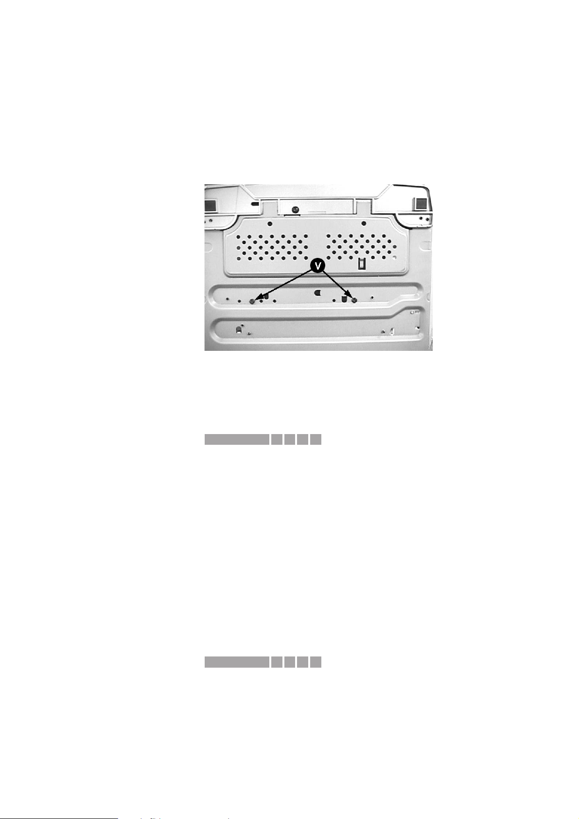
01.28 TYPENUMBER(S): FW-D1, FW-D5
INFORMATION : During the introduction of ASD-1 DVD Module there is a problem with
vibration noise during DVD play. This vibration noise is solved by the
addition of 2 screws D3 x 12 to tighten the ASD-1 DVD Module to the
Bottom plate (pos 236).
These additional screws have an impact on the dismantling steps
given in the Service Manual.The picture below shows the screw
location on the bottom plate (see screws V).
Take care when dismantling the DVD/DAC Module.
REMARKS :
01.29 TYPENUMBER(S): FW-D5/22
SYMPTOM :
Poor picture quality when the set is connected to the TV with a
standard SCART cable.
CURE : In the TV-set pin 19 and 20 are connected via an internal loop.
Via the standard SCART cable also pin 19 and pin 20 of the AV
Board are short-circuited. As pin 20 is grounded on the AV Board this
results in poor picture quality on the TV-set.
Interrupt the ground connection for SCART socket pin 20 on the AV
Board by cutting the copper track.
REMARKS :
01.30 TYPENUMBER(S): FW-V39
SYMPTOM :
The set is responding to some TV remote control codes
CURE : Some TV RC codes will activate VCD and other functions.
This problem is resolved by replacing the microprocessor IC 7401 on
the Front board by one with software version 17.
The new IC is available with othering code 9965 000 06154.
REMARKS :
X511IRIS CODE
X331IRIS CODE
Service Newsletter 2001 – BCU Audio 12/16
Page 44
01.31 TYPENUMBER(S): FW-V39
SYMPTOM :
CD, Tape and Tuner not working, transistor 7233 (BD242BFP) blown.
CURE : Due to high inrush current at excessive mains supply values
transistor 7233 becomes defective (C-E shor ted). This causes a
sudden increase of supply voltages +PA, +LED, +12A and +12M
(jumping from +12 volts to +30 volts) killing other components along
the way.
SOLUTION: Reduce value of Elcap 2245 from 1000µF 16V to 220µF
16V (4822 124 40196).
REMARKS : Preventive action: In countr ies with high mains fluctuation it is
recommended to exchange 2245 on every set brought in for repair.
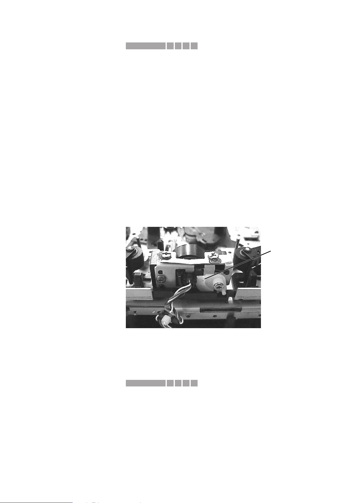
01.32 TYPENUMBER(S): MC-50, MC-70
INFORMATION : Tape Deck Record/Playback head replacement tip.
After replacement of the Record/Playback head (pos 1) it is ver y
important to align it to the Forward position as given in picture below.
If this is not done, there is risk of damaging the gear.
REMARKS :
01.33 TYPENUMBER(S): MZ-3, MZ-33
SYMPTOM :
Hum noise picked up from transformer is audible.
CURE : Replace inductor 5553 by a jumper.
REMARKS : The modification has been implemented in production from week
0048 onwards.
1451IRIS CODE
Turn the Rec/Pb head
until the white gear rack
reaches this position
D611IRIS CODE
Service Newsletter 2001 – BCU Audio 13/16
Page 45
01.34 TYPENUMBER(S): SA100, SA101, SA107, SA125, SA126
INFORMATION : The Instruction For Use is not available as ser vice spare par t.
It can be viewed or downloaded as PDF-file from the Rush Customer
Support inter net site http://www.rush.philips.com/support.html
REMARKS :
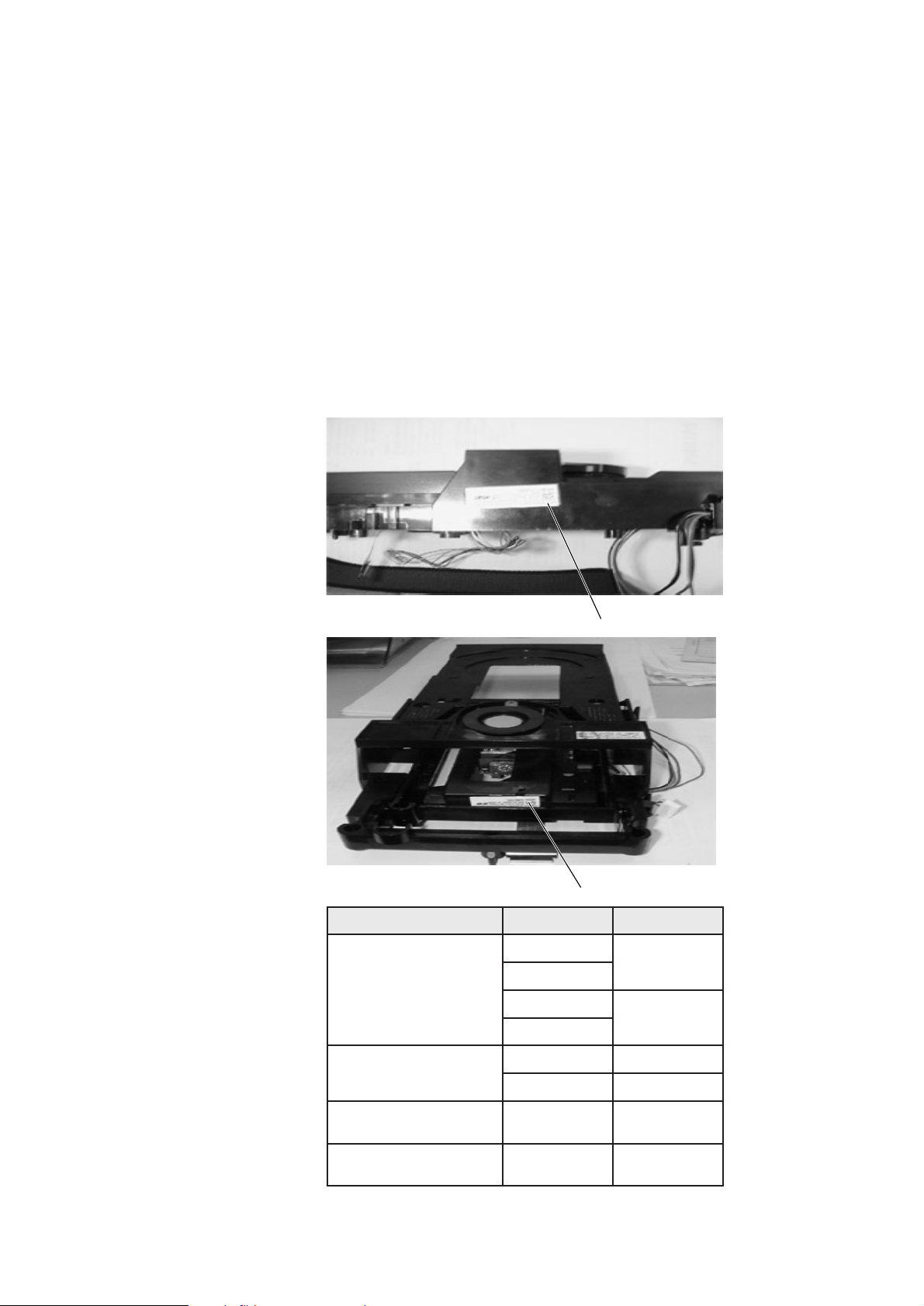
01.35 TYPENUMBER(S): SD100
INFORMATION : The SD100 has been produced with different Loader/CD-drive
combinations.When replacing the CD-drive it is essential to order the
correct type of drive. Both, Loaders and CD-drives, can be identified
by their type-labels (see pictures below).The corresponding
codenumbers can be found in the attached cross-table.
REMARKS :
tinUredaoL evirD-DC rebmunedoC
16/0121L )196207414013(
36/0121L )107207414013(
2021MAV
102022205039
J2021MAV
20/2021MAV
202022205039
J20/2021MAV
56/0121L )562023205039(
86/0121L )862023205039(
2021MAV102022205039
21/2021MAV212022205039
14/0121L )072207414013(
34/0121L )016207414013(
1021MAV101022205039
54/0121L )541023205039(
84/0121L )841023205039(
1021MAV101022205039
VAM label
Loader label
Service Newsletter 2001 – BCU Audio 14/16
Page 46
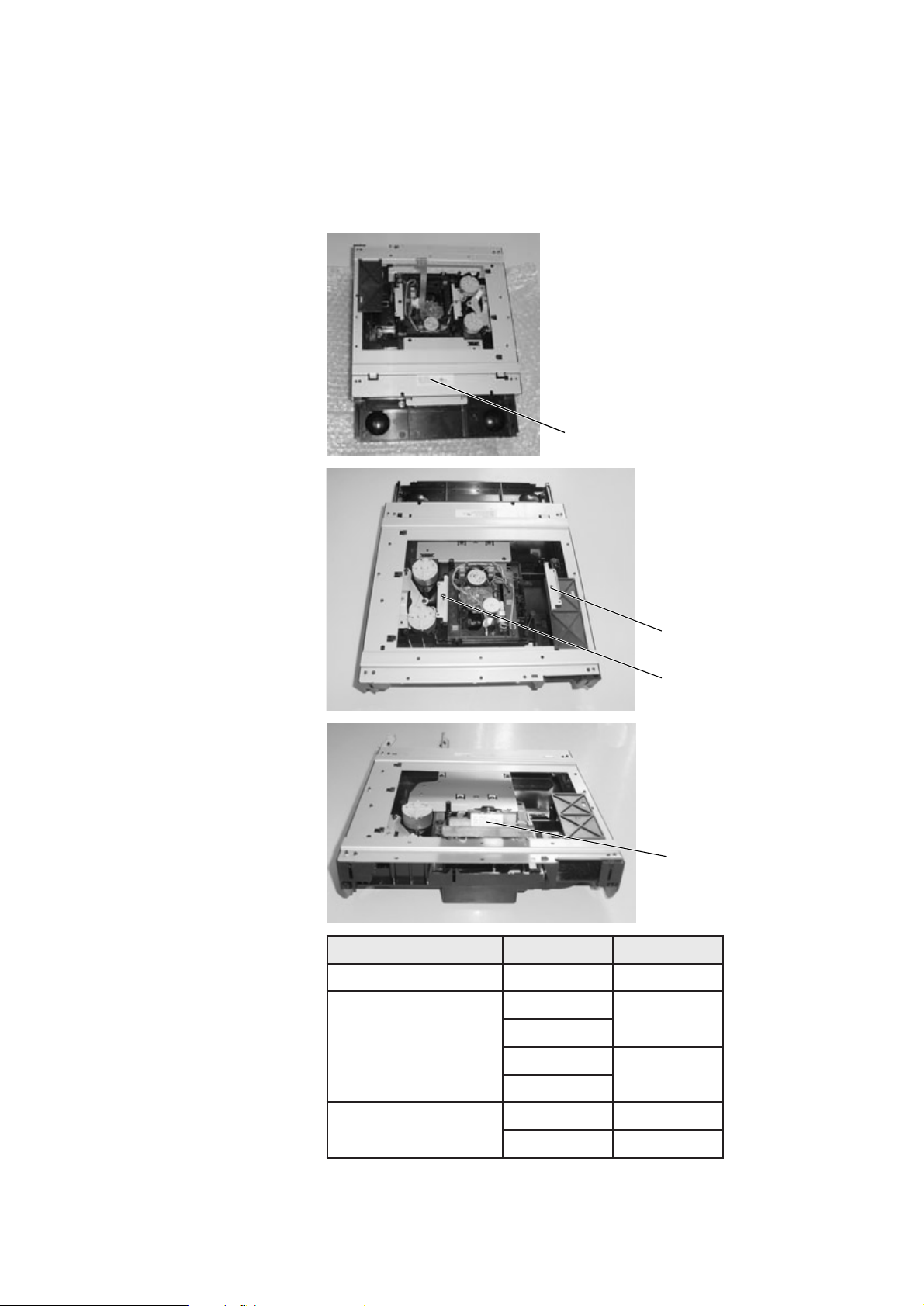
01.36 TYPENUMBER(S): SD300
INFORMATION : The SD300 has been produced with different Loader/CD-drive
combinations.When replacing the CD-drive it is essential to order the
correct type of drive. Both, Loaders and CD-drives, can be identified
by their type-labels (see pictures below).The corresponding
codenumbers can be found in the attached cross-table.
REMARKS :
tinUredaoL evirD-DC rebmunedoC
11/3021C )195207414013(30/1021MAV301022205039
12/3021C )146207414013(
2021MAV
102022205039
J2021MAV
20/2021MAV
202022205039
J20/2021MAV
82/3021C )822024205039(
2021MAV102022205039
21/2021MAV212022205039
Pull out CD-drive to see
the VAM label
Remove screw
Remove the steel cover piece
To check the VAM label, the CD-drive
must be dismantled as follows:
SD300 Unit label
Service Newsletter 2001 – BCU Audio 15/16
Page 47

01.37 TYPENUMBER(S): SD300
INFORMATION : Correction to the Service Manual, Partslist MPEG-board
The typenumber of the MPEG-2 A/V processor (item 7601) reads
“CL8830A” instead of “CL8860 QFP208”.
The codenumber remains unchanged:
7601 3141 018 50470 CL8830A (C-CUBE)
REMARKS :
Service Newsletter 2001 – BCU Audio 16/16
 Loading...