

Page 1

For internal use only PHILIPS
ISSUE SNL2000.07 (00-09-11)
Published by:
Service Depar tment Audio
BUSINESS CREATION UNIT AUDIO
07.01 TYPENUMBER(S): AJ3935, AJ3936
SYMPTOM :
The Compact Disc gets sticked onto the CD-Clamper assembly.
CURE : Replace the old Clamper assembly (items 434, 436 and 437) by the
new one 3140 117 59800.
REMARKS : New CD-Clamper assemblies are used in production from week 0025
onwards.
07.02 TYPENUMBER(S): AS800C, AS801C, FW-C28, FW-C38, FW-C39, FW-C40, FW-C55,
FW-C58, FW-C71, FW-C72, FW-P75, FW-P78, FW-C80, FW-C83,
FW-C85, FW-M55, FW-V28, FW-V55, FW545C/34, FW548C/21K/34,
FW590C/34, FW595C/21K, FW830C/22/34, FW840C/22, FW850C,
FW855C, FW860P, FW870C/22, FW878C/34, FW880P, FW880W,
FW890P/22, FW898W/34, MZ7
INFORMATION : Service Manual, Partslist
The Cam Gear (pos 25) of the Tape mechanism has been added as
service spare par t. The codenumber reads 9965 000 06443.
REMARKS :
07.03 TYPENUMBER(S): AZ1030
INFORMATION : Due to supply shortfall of servo IC TDA7073A, the CD par t of the
Combi board assembly had to be redesigned for LA6530.The new
Combi board assemblies are used in production alternatively.
For repair infor mation on new Combi board assembly see Service
Information A00-558 (3140 785 22460).
REMARKS : Alternative Combi board assemblies are used in production from
week 0028 onwards.
9162IRIS CODE
SERVICE NEWSLETTER
Service Newsletter 2000 – BCU Audio 1/10
Page 2

07.04 TYPENUMBER(S) : AZ2402, AZ2407, AZ2420, AZ2425
SYMPTOM :
The set cannot read the TOC at low battery supply.
CURE : Change transistor 7217 from BC557B to BC337-25
(4822 130 41246).
REMARKS : The modification has been implemented in production from week
0025 onwards.
07.05 TYPENUMBER(S): AZ7902, AZ9001, AZ9002, AZ9003, AZ9011, AZ9101, AZ9102,
AZ9103, AZ9104, AZ9106, AZ9111, AZ9113, AZ9141, AZ9142,
AZ9143, AZ9201, AZ9202, AZ9203, AZ9211, AZ9213, AZ9214,
AZ9218
INFORMATION : Correction to the Service Manual, Service Test Program
The correct procedure to enter the Service Test Program is as
follows:
• Disconnect the AC/DC-adaptor and remove batteries
• Open the CD-Door
• Hold the buttons
“MODE” & “STOP”
depressed
• Connect the AC/DC-adaptor or insert batteries
The display shows the software version number (i.e. “S-13”).
REMARKS :
07.06 TYPENUMBER(S): AZ9001, AZ9002, AZ9003, AZ9011, AZ9101, AZ9102, AZ9103,
AZ9104, AZ9106, AZ9111, AZ9113, AZ9141, AZ9142, AZ9143,
AZ9201, AZ9202, AZ9203, AZ9211, AZ9213, AZ9214, AZ9218
INFORMATION : Service Manual, Partslist
The following parts have been added as service spare part:
3103 308 84070 LCD-2 DORIS (WK-TZA065)
3103 304 68010 ZEBRA-STRIP-2
3103 304 68020 MEMBRANE-KEYBOARD-2
REMARKS :
07.07 TYPENUMBER(S): AZ9214
INFORMATION : Service Manual, Table of Accessories
The missing service codenumbers for the Pouch and the Cord
Remote Control are available now:
3140 113 10360 AY3266/00 Pouch
3103 309 72380 AY3767/00 Cord Remote Control
REMARKS :
X272IRIS CODE
Service Newsletter 2000 – BCU Audio 2/10
Page 3

07.08 TYPENUMBER(S): CDR570, CDR770, CDR775, CDR776, CDR785, CDR930, CDR950,
CDR951, FW-R7, FW-R8
INFORMATION : Introduction of COMPAIR for CDR 3rd generation recorders
CDR570, CDR770, CDR775, CDR776, CDR785, CDR930, CDR950,
CDR951, FW-R7, FW-R8
With the new release COMPAIR 1.4 (ordernumber 4822 727 21637)
the existing COMPAIR Tool (star ter kit with order number
4822 727 21634) has been extended to be applied for the CDR 3rd
generation Recorders.With this tool the diagnosing of the set can be
done in an interactive way. In the tool also the adjustment procedure
has been implemented.This is absolutely necessary in case the
CDR-mainboard and/or (CDR-loader) CDM is disconnected from the
matched production combination.
For Author ised ser vice workshops which have installed COMPAIR 1.4
the following CDR-modules
3104 129 52511 for CDR570 and CDR930,
3104 129 52521 for CDR770,
3104 129 52530 for CDR775 and CDR776,
3104 129 52540 for CDR950 and CDR951,
3104 129 52580 for CDR785,
3104 129 52590 for FW-R7 and FW-R8
can be repaired on component level as explained in the Cologne
Training session (held in week 0019 and 0020).
In the Cologne Training we have explained the need of the interface
board to be used with COMPAIR.The codenumber for this board
reads 7104 086 91110, the connection cable to the module is
available with 3104 157 11120.
Based on the feedback from the Competence Centres a new simple
board will be introduced within a few weeks. The codenumber for this
board plus module connection cable reads 3122 785 90200.
Upgrading SW with the help of COMPAIR is not possible yet.
To have all modifications during production implemented on the CDRmainboard the following actions have to be taken:
Software version 1.04 & 91.48:
It is advised to replace mainboards stamped A2 or A3 by at least
production stamp A7 and always adjust via COMPAIR.
For CDR570 and CDR930 the ordernumber for the CDR mainboard
reads 3104 128 05840.
For CDR770 the ordernumber reads 3104 128 05850.
Other models have never been produced with stamp A2 or A3.
Software version 1.23 & 91.63:
• Update to the latest SW version (see SNL2000.03.09)
• Replace capacitors 2725, 2726 and 2727 by 100nF 50V
(see SNL2000.07.10)
• Replace capacitor 2322 by 1.5nF (see SNL2000.07.12)
• Add resistor 27Ω (see SNL2000.07.13)
• Always adjust via COMPAIR
Service Newsletter 2000 – BCU Audio 3/10
Page 4

Software version 1.34 & 91.80:
• Update to the latest SW version (see SNL2000.03.09)
• Replace capacitors 2725, 2726 and 2727 by 100nF 50V
(see SNL2000.07.10)
• Replace capacitor 2322 by 1.5nF (see SNL2000.07.12)
• Add resistor 27Ω (see SNL2000.07.13)
• Always adjust via COMPAIR
Software version 1.43 & 91.91
• Update to the latest SW version (see SNL2000.03.09)
• Replace capacitors 2725, 2726 and 2727 by 100nF 50V
(see SNL2000.07.10)
• Replace capacitor 2322 by 1.5nF (see SNL2000.07.12)
• Add resistor 27Ω (see SNL2000.07.13)
• Only adjust via COMPAIR if servo components have been
changed
Software version 1.47 & 91.96
• Update to the latest SW version (see SNL2000.03.09)
• Replace capacitors 2725, 2726 and 2727 by 100nF 50V
(see SNL2000.07.10)
• Replace capacitor 2322 by 1.5nF (see SNL2000.07.12)
• Add resistor 27Ω (see SNL2000.07.13)
• Only adjust via COMPAIR if servo components have been
changed
Solved phenomena with the following software version:
Version 1.23
• improvement and shortening startup procedure
• CD-sync start procedure improved
Version 1.34
• further improving and shor tening star tup procedure
Version 1.43
• does not start : display shows insert disc
• does not start : display shows OPC error
• does not start finalising / unfinalising
• extra track increments during analog and digital recording
• does not start erase
• does not start analog recording
• bad audio
• player in standby during recording or finalising
Version 1.47
• does not start: set in hangup
• in hangup after finalising / unfinalising
Version 1.51
• does not recognize the Philips HR100 CDR disc
REMARKS : Only modules of the 3rd generation CDR can be repaired via
COMPAIR. For 1st and 2nd generation modules the central repair on
modules will be continued. It is our goal to minimize the central repair
activities for 3rd generation and future models.
Service Newsletter 2000 – BCU Audio 4/10
Page 5

07.09 TYPENUMBER(S): CDR570, CDR770, CDR775, CDR776, CDR930, CDR950, CDR951
INFORMATION : Temporary from production start onwards item 2101 with value 100nF
16V has been applied. Due to filament voltage, the 16V spec is too
low. The capacitor has to be replaced by 100nF 50V
(4822 126 13838).
REMARKS :
07.10 TYPENUMBER(S): CDR570, CDR770, CDR775, CDR776, CDR930, CDR950, CDR951
INFORMATION : Temporary from production start onwards item 2725, 2726, 2727 with
value 100nF 16V have been applied. Due to filament voltage, the 16V
spec is too low. The capacitors have to be replaced by 100nF 50V
(4822 126 13838).
REMARKS :
07.11 TYPENUMBER(S): CDR570, CDR770, CDR771, CDR775, CDR776
INFORMATION : The Power Supply Unit of above mentioned sets has been changed
from “PSU CDR3 SINGLE RANGE” to “PSU CDR3 ECONOMY”.
The codenumbers of the complete assemblies read as follows:
For /00/10/14 (EURO) : PSU CDR-3 ECONOMY EURO 20PS202
with codenumber 3122 427 22000
For /01/06/13 (WR) : PSU CDR-3 ECO WR 20PS315
with codenumber 3122 427 22020
For /17 (USA) : PSU CDR-3 ECO USA
with codenumber 3122 427 22010
REMARKS : The functionality of both power supplies is equal and backwards
compatible.For details see Service Information A00-254
(3104 125 40180) with circuit description, circuit diagrams and trouble
shooting.
07.12 TYPENUMBER(S) : CDR570, CDR770, CDR775, CDR776, CDR930, CDR950, CDR951
SYMPTOM :
The CD-Recorder does not recognize the Philips HR100 CDR
(“No disc” is shown on the display).
CURE : The problem can be solved by the following hardware and software
modification:
1. Hardware modification at the topside of the Main Board
• Change capacitor 2322 from 3.3nF to 1.5nF (4822 126 14247)
165CIRIS CODE
Service Newsletter 2000 – BCU Audio 5/10
Page 6
2. Software modification at the topside of the Main Board
• Update software version of item 7208 (in socket) to version 92.01.
Programmed flash with version 92.01 or higher can be ordered with
codenumber 3104 123 94850.
• Update software version of item 7703 (soldered) to version 1.51.
Programmed flash with version 1.51 or higher can be ordered with
codenumber 3104 123 85760.
REMARKS : Software versions lower than 1.43 & 91.91 which have been updated
to the latest version must always be re-adjusted with the
COMP AIR T ool.Workshops which do not use COMPAIR have to
replace these 3rd generation CDR-modules.
See also Service Newsletter SNL2000.07.08.
07.13 TYPENUMBER(S): CDR570, CDR770, CDR775, CDR776, CDR930, CDR950, CDR951
SYMPTOM :
Clock jitter in DASP-IC item 7701 on CDR Mainboard, this can result
in hang-up of the microprocessor.After Power off, Power on the set
will normally star t but the phenomenon might return again.
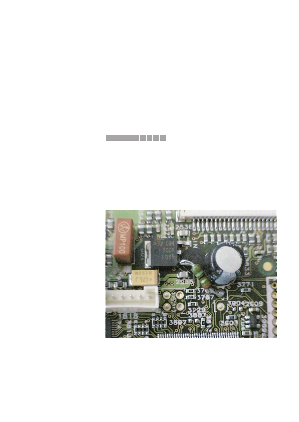
CURE : To solve this problem in running production and as service solution,
the power supply of D3V3 has been improved by adding a resistor of
27Ω (CRB 1/6W A PM5 and order number 4822 116 52188) between
“disconnected” pin 1 of item 7535 and mass (hole 2 of item 1701).
See part of the main board (top side view) for location of the resistor.
REMARKS : With release of the A9 version of CDR Mainboard this resistor is
implemented in printed board layout and mounted in production.
1652IRIS CODE
Service Newsletter 2000 – BCU Audio 6/10
Page 7

07.14 TYPENUMBER(S): CDR570, CDR770, CDR775, CDR776, CDR930, CDR950, CDR951
INFORMATION : All returned discs, causing complaints on the CDR sets of the 3rd
generation, have been investigated. This results in the following
conclusion:
The Philips Megalife disc has been produced by Ricoh and Mitsui.
Most of the problems have been found with discs produced by Mitsui.
How to recognize the production centre?
Ricoh : made in USA printed on the jewel box
Mitsui : made in Europe printed on the jewel box.
Please note: Discs packed in a carton box (5pcs/carton) are
marked with made in USA!
Ricoh : Marked Audio HR100
Mitsui : Marked Audio100
Ricoh : serial number on inner circle consists of 4 character + 12
digits (e.g. ALXH 06109902214 3)
Mitsui : serial number on inner circle consists of 12 digits
(e.g. 9287 2217 4953)
It is not advised to apply the Mitsui disc in 3rd generation CDR
recorders up to software version 1.51.
REMARKS :
07.15 TYPENUMBER(S): CDR785, CDR786
INFORMATION : The sets are equipped with a special DEALER MODE.
This mode blocks the trays of the CDC- and CDR module to prevent
customers from fetching out CDs from exhibition sets.
The dealer mode can be switched on/off as follows:
1) Switch the set with the Remote Control to standby mode
2) Press the [DISPLAY] key for longer than 5s
→ Display shows
“DEALER MODE ON”
respectively
“DEALER MODE OFF”
REMARKS :
07.16 TYPENUMBER(S): CDR785, CDR786
INFORMATION : On the black versions CDR785/00 and CDR785/17 the feet pos. 22
have been changed from silver to anthracite metallic.
The codenumbers read as follows:
old: 4822 462 42159 foot silver
new: 4822 462 11174 foot anthracite metallic
REMARKS : The modification has been implemented in production from week
0032 onwards.
Service Newsletter 2000 – BCU Audio 7/10
Page 8
07.17 TYPENUMBER(S): CDR785, CDR786
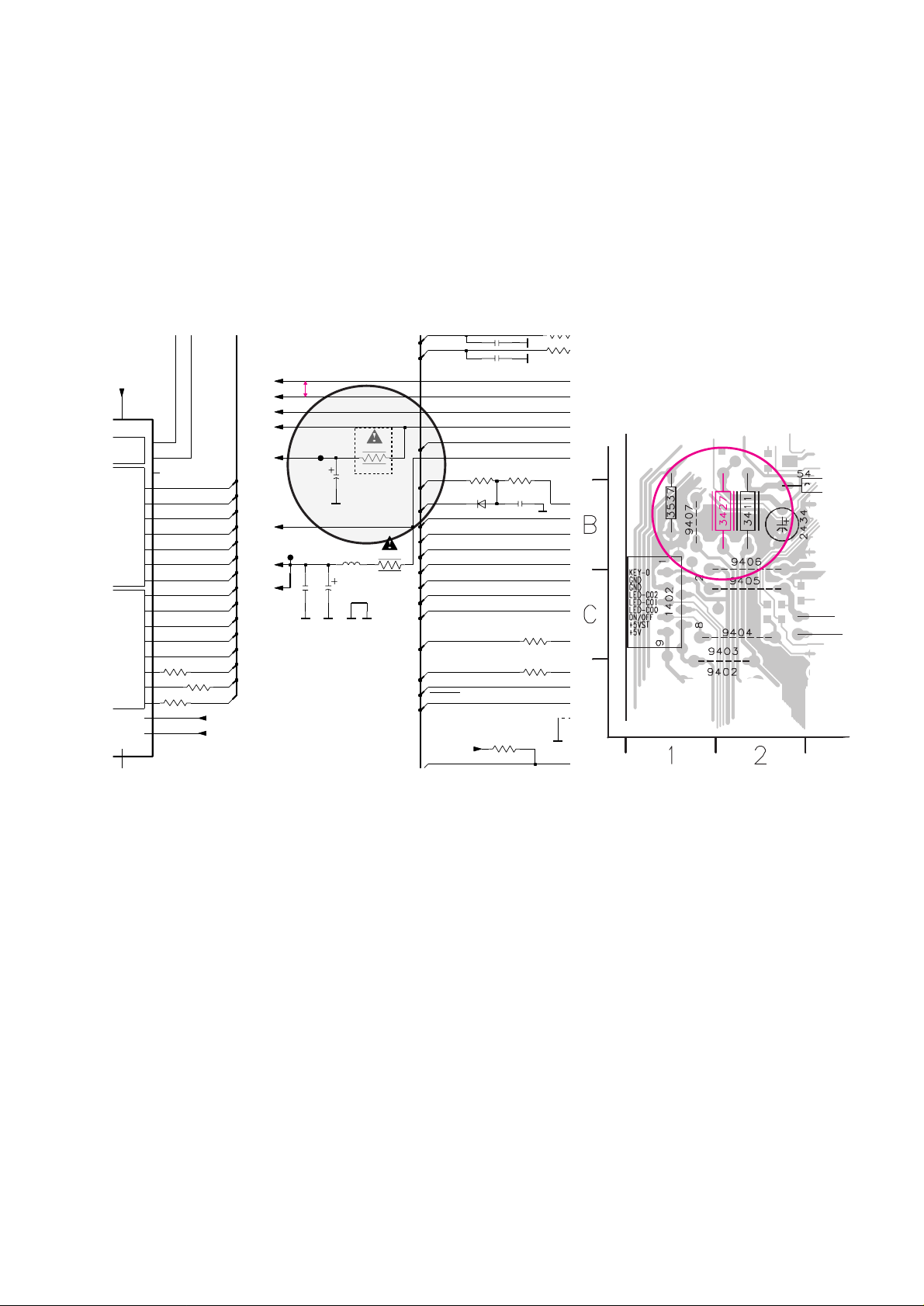
INFORMATION : Production started with the OTP-version “TMP88PU77F”of the
microprocessor.
Service will deliver final mask version “TMP88CU77F-CDR785.2”
(3103 308 84170).
In case an OTP-version has to be replaced by the mask version
resistor 3427 has to be removed.
Reason:The mask version has an internal connection between the
supply pins 32 (+µP) and 51 (+D).
REMARKS :
07.18 TYPENUMBER(S): EXP101, EXP103
INFORMATION : Following components have been changed to improve the CD start-
up and EMC behaviour:
RP36 changed from 47kΩ to 100kΩ (4822 117 13632)
RM87 and RM88 changed from 100Ω to 330Ω (4822 051 10331)
RD28, RD29 and RD30 changed from 100Ω to 1kΩ
(4822 051 30102)
RD41, RD42 and RD43 changed from 22Ω to 1kΩ (4822 051 30102)
REMARKS : Modifications are implemented since production start.
copperside view
P7
P6
+
-
+
+
SUPP
2416
330p
100u
2434
D
D
3479
100R
F403
D
3460
470R
3503
1K
5407
2u2
10p2411
100R
3476
31
VASS
30
VDD-I|O
32
VDD-VFT
51
9
VAREF
P70
41
P71
42
43
P72
P73
44
P74
45
P75
46
P76
47
P77
48
P80
49
P81
50
2
P60
33
P61
34
P62
35
P63
36
P64
37
P65
38
P66
39
P67
40
D
1N4148
6404
2432
47u
D
2R2
3411
D
270R
3518
100R
3482
10p2412
D
94
D
2K7
3451
270R
3516
100n
2431
3441 1K
F409
+5VST
+5V
+yP
+C
FAN
+F
CWReset
KEY0
AnaSw0
AnaSw2
SPLY_ON1
SPLY_ON2
+C
I2CW_DATA
I2CW_CLK
MUTE
AnaSw1
DigSw2
DigSw1
G7
G3
G15
G14
G13
G1
G5
G6
DigSw0
G10
G12
G9
P2
P2
G11
+D
-F
-30V
G8
G4
G2
+yP
+D
CDSwInfo
CWReqKbe
+C
4R7
3427
for OTP version
of µP only
to be removed
if mask version
of µP is used
5V typ.
5V
-8,
0/5
4,1V +/- 0,4V
-29,3V +/- 2,2V
5V +/- 0,25V
3,2V
5V
4,9V
3,7/3
5V +/- 0,25V
5V typ.
5V
4,4V
0/5
0/5
0/5
0/5
CD/C
4,9V
5V
Service Newsletter 2000 – BCU Audio 8/10
Page 9

07.19 TYPENUMBER(S) : FW-C1, FW-C3, FW-C10, FW-C30, FW-C-35
SYMPTOM :
After record, there is no (or wrong) output when playing back the
tape.
CURE : Replace the Erase Head if there is no oscillation at jumper 9730 (test
point 5) although the erase oscillator is working normally (no
defective components).
REMARKS : The problem is caused by a poor batch of Erase Heads.
It is resolved from production week 0009 onwards.
07.20 TYPENUMBER(S) : FW-C1, FW-C3, FW-C10, FW-C28, FW-C30, FW-C35, FW-C38,
FW-C39, FW-C40, FW350C, FW390C, FW391C, FW396C, FW398C,
FW540C, FW545C, FW548C, FW555C, FW585C, FW590C,
FW595C, FW748P, FW768P, FW798W, FW830C, FW840C, FW870C,
FW878C, FW890P, FW898W, FW910R, FW930, MZ7
INFORMATION : Correction to Service Manual, Mechanical Partslist 3CDC99 module
Some of the published codenumbers are wrong.
Pos no. Description should read
––––––––––––––––––––––––––––––––––––––––––
3 Guiding left 4822 463 11235
4 Guiding right 4822 463 11236
12 Rubber 4822 446 12146
13 Rubber 4822 446 12146
21 Drawer 3104 304 66800
22 Bracket Tumbler 4822 402 11236
23 Spring 4822 492 11721
40 Slide 4822 463 11237
115 Carousel 3103 304 66810
REMARKS :
07.21 TYPENUMBER(S): FW-C10/21
INFORMATION : Correction to the Service Manual, Partslist
The codenumber for the Mains transformer 5001 should read
4822 146 10956.
REMARKS :
X652IRIS CODE
Service Newsletter 2000 – BCU Audio 9/10
Page 10

07.22 TYPENUMBER(S): FW-R7, FW-R8
INFORMATION : The sets are equipped with a special DEALER MODE.
This mode blocks the trays of the CDC- and CDR module to prevent
customers from fetching out CDs from exhibition sets.
The dealer mode can be switched on/off as follows:
1) Switch the set with the stanby-button to standby mode
2) Press the [DISPLAY] key for longer than 5s
→ Display shows “
DEALER MODE ON“
respectively
“
DEALER MODE OFF“
REMARKS :
Service Newsletter 2000 – BCU Audio 10/10
 Loading...