

Page 1

For internal use only PHILIPS
ISSUE SNL2000.08 (00-10-31)
Published by:
Service Depar tment Audio
BUSINESS CREATION UNIT AUDIO
08.01 TYPENUMBER(S): AZ1030, AZ1035, AZ1040, AZ1045, AZ1120, AZ1550, AZ1560,
AZ1565, AZ2000, AZ2010, AZ2020, AZ2025
INFORMATION : Correction to the Service Manual, Mechanical Partslist
The codenumber for Motor (item 115) of the Tape Deck should read
4822 361 21656.
REMARKS :
08.02 TYPENUMBER(S): AZ1040, AZ1045
INFORMATION : Correction to the Service Manual, Mechanical Partslist
The codenumber of the CD Mechanism (DA11N) is missing.
It is available with codenumber 3103 309 05290.
REMARKS :
08.03 TYPENUMBER(S): AZ1560, AZ1565
INFORMATION : During production, the tuner module has been changed from “ECO5”
to “ECO6”. For repair information of the ECO6 tuner board assembly
refer to Service Information A00-560 (3140 785 22440).
REMARKS : ECO6 tuner board assemblies are used in production from week
0034 onwards.
08.04 TYPENUMBER(S): AZ2020, AZ2025
INFORMATION : In order to solve accidental mute problems on /01, /11 and /16
versions, the AF & POWER BOARD has been modified.
For servicing the new AF & POWER BOARD assembly refer to
Service Information A00-561 (3140 785 22560).
REMARKS : New AF & POWER BOARD assemblies are used in production from
week 0037 onwards.
SERVICE NEWSLETTER
Service Newsletter 2000 – BCU Audio 1/7
Page 2
08.05 TYPENUMBER(S): CDC775, CC3000, CC4000
SYMPTOM :
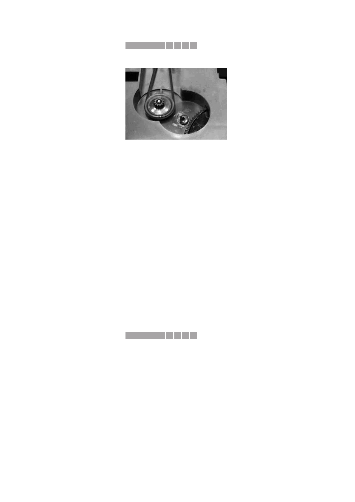
CDC Tray does not open, the spindle for the Gearwheel (pos 95) is
broken (see picture below).
CURE : For integral cost reasons it is advised to exchange the complete set.
REMARKS : Sets affected were produced before production week 0026.
08.06 TYPENUMBER(S): CDR570, CDR770, CDR775, CDR776, CDR785, CDR786, CDR930,
CDR950, CDR951, FW-R7, FW-R8
INFORMATION : For service purpose an extension flexfoil for the connection of CDR
mainboard connector 1000 to CD-drive has been taken on stock.It is
available with codenumber 3104 157 11510.
The extension flexfoil enables measurements on the top side of the
mainboard without disconnecting or damaging the flex-connection
from the mainboard. Please note that all important measuring points
are positioned on the bottom side of the mainboard.
REMARKS : Take care to remove the extension flexfoil before retur ning the set to
the customer.
08.07 TYPENUMBER(S): CDR775
SYMPTOM :
In dubbing mode, the first milliseconds of the track are not recorded.
CURE : New software version 3.6 for CD-mainboard.
Programmed IC 7202 (soldered) can be ordered with codenumber
3104 123 85630.
REMARKS : The built-in CD software version can be read out by the electrical
service diagnostics.This mode can be entered by holding
<PLAY/PAUSE> & <FFWD> keys depressed while switching power
on.
The new software has been implemented in production with factor y
change code VN05 from week 0037 onwards.
155CIRIS CODE
X611IRIS CODE
Service Newsletter 2000 – BCU Audio 2/7
Page 3
08.08 TYPENUMBERS : CDR570, CDR770, CDR771, CDR775, CDR776
SYMPTOM :
The set is switched to stand-by after power on.
CURE : The problem occurs only with the recently introduced new power
supply unit “PSU CDR3 ECONOMY”.
It can be fixed with the following modification:
• change item 3127 (current sense resistor) from 1.5Ω to 1Ω
(4822 116 80176)
• change item 6141 (zener diode) from 18V to 20V (4822 130 10656)
REMARKS : The above modification has been implemented in production from
week 0034 onwards.
08.09 TYPENUMBER(S): CDR785, CDR786, FW-R7, FW-R8
SYMPTOM :
Clock jitter in DASP-IC item 7701 on CDR Mainboard can result in
hang-up of the microprocessor.After Power off, Power on the set will
normally star t but the phenomenon might return again.
CURE : To solve this problem in running production and as service solution,
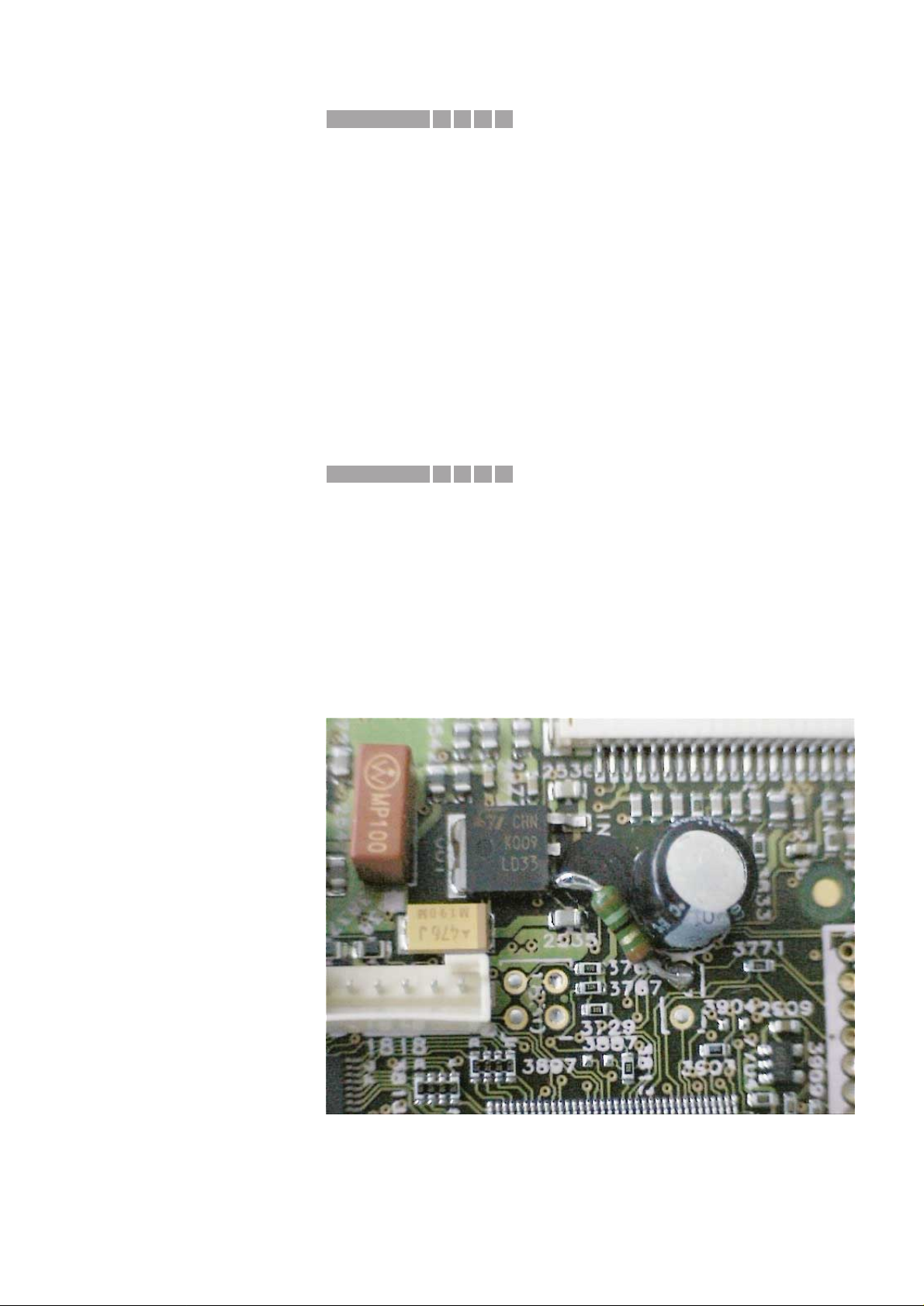
the power supply of D3V3 has been improved by adding a resistor of
27Ω (CRB 1/6W A PM5 and codenumber 4822 116 52188) between
“disconnected” pin 1 of item 7535 and ground (hole 2 of item 1701).
See part of the main board (top side view) for location of the resistor.
REMARKS : With release of the A9 version of CDR Mainboard this resistor is
implemented in printed board layout and mounted in production.
1652IRIS CODE
X11CIRIS CODE
Service Newsletter 2000 – BCU Audio 3/7
Page 4
08.10 TYPENUMBER(S): CDR785, CDR786, FW-R7, FW-R8
SYMPTOM :
When source “AUX DIGITAL” is selected and no source is connected
or it is switched off, there is a burst of noise audible through the
speakers ever y 3 seconds. If a digital source is connected and
switched on, the noise disappears.
CURE : • change SMD resistor
3300 on Interface Board (CDR785, CDR786) resp.
3358 on Digital Switch Board (FW-R7, FW-R8)
to 6.8kΩ (4822 117 11507)
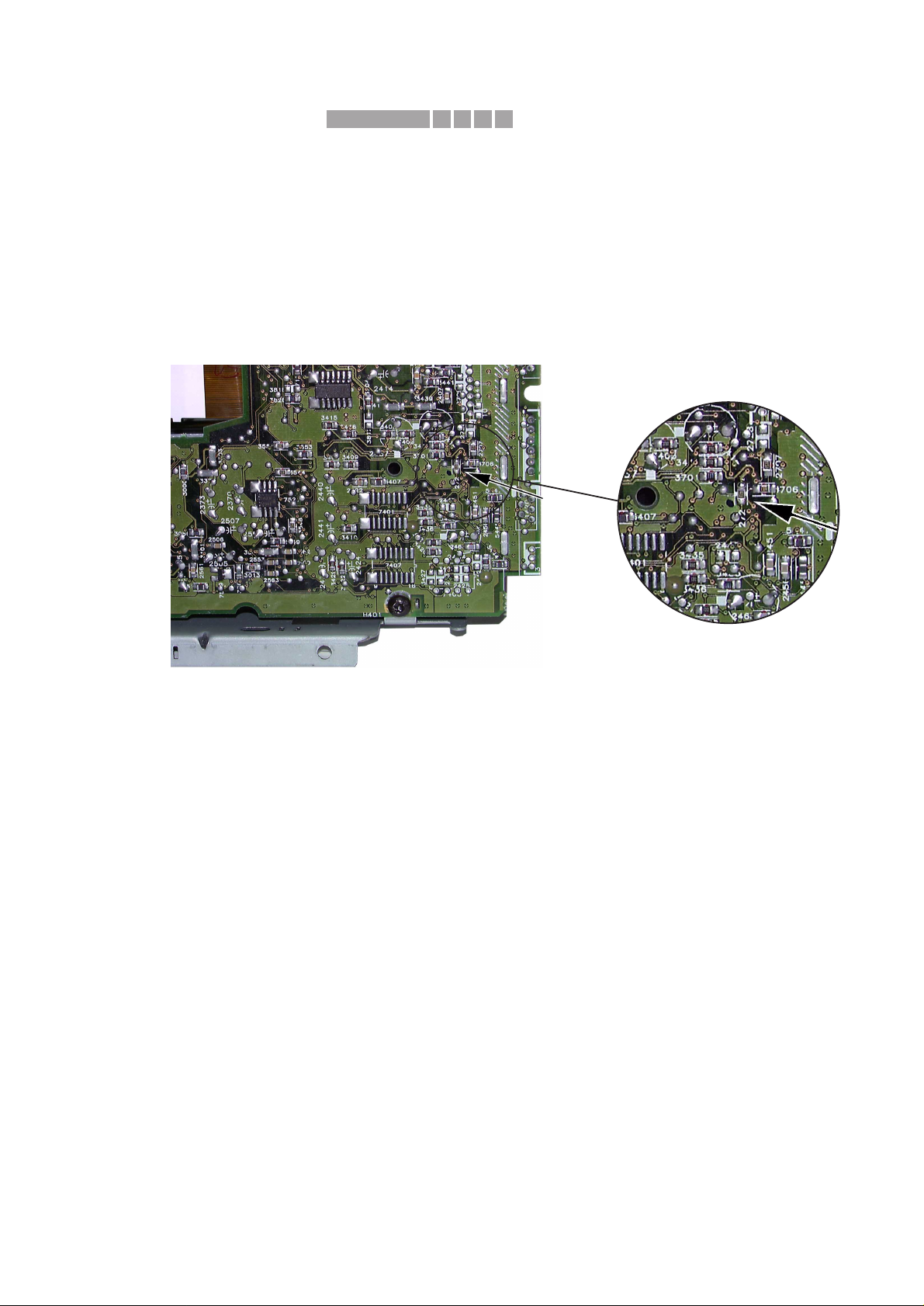
• add resistor 2721 (6.8kΩ 4822 117 11507) on the bottom side of
CDR Main Board → see picture below
REMARKS : This solution will also be implemented in production as a running
change.
08.11 TYPENUMBER(S): EXP101, EXP103
INFORMATION : Correction to the Instruction For Use
The description of chapter “Remote Control” is not clear.
The Remote Control AY3767 will work with EXP101 only.
It cannot be used with EXP103.
REMARKS :
945FIRIS CODE
Service Newsletter 2000 – BCU Audio 4/7
Page 5
08.12 TYPENUMBER(S): FW-C50, FW-C55, FW-C58, FW-C70, FW-C71, FW-C72, FW-C80,
FW-C83, FW-C85, FW-C90, FW-C870, FW-M55, FW-P73, FW-P75,
FW-P78, FW-P88, FW-P880, FW-P900, FW-V55
SYMPTOM :
When a wireless heaphone (eg. SBC8320, SBCHC630, etc.) is
connected to the headphone socket, the headphone sound is
continuously interrupted.
CURE : The phenomenon is caused by a mis-match between the output
impedance of the heaphone amplifier (32Ω - 1kΩ) and the input
impedance of the wireless transmitter (10kΩ).
Due to the high input impedance of the transmitter the signal
becomes so high that the muting circuit is triggered.
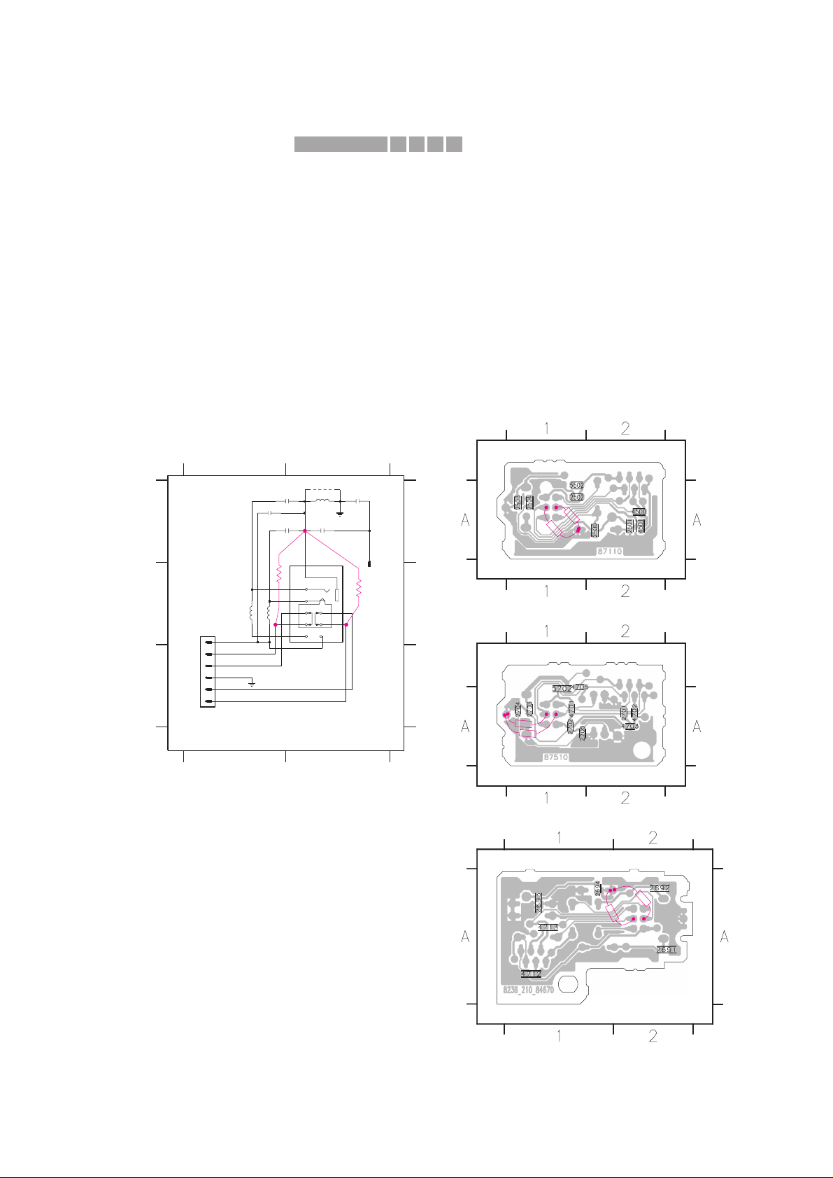
The problem is solved by adding 2 resistors, 330Ω (4822 116 52219)
from the headphone switch pin 2 and 5 to common ground.
Headphone Circuit Headphone SMD layout (copper side view)
–––––––––––––––––––––––––––––––– –––––––––––––––––––––––––––––––––––
REMARKS :
3139 113 3431 pt1 dd wk0023
For FW-D1 & FW-D5
Front - H/P Part - Copper Side View
This assembly drawing shows a summary of all possible versions.
For components used in a specific version see schematic diagram and respective parts list.
For FW-C5..., FW-V5..., FW-M5...,
FW-C7... & FW-P7...
AF6 - H/P Part - Copper Side View
12
12
A
B
C
A
B
C
1500 B2
1501 A2
1502 B1
2500 A2
2501 A2
2502 A1
2503 A2
2504 A2
5500 A2
5501 B1
5502 B1
9500 A2
22n
2502
1
2
3
4
5
6
a
a
100n
2504
1501
1
FE-BT-VK-N
1502
TC38
9
8
7
1
2
3
4
5
6
2u2
5502
1500
# 9500
5501
2u2
2u2
5500 # 2501
22n
2503
100n
22n
2500
L
Lhp
DPL_SW
R
Rhp
GNDa
# : Provision
For FW-C8..., FW-P8..., FW-C9... & FW-P9
Front - H/P Part - Copper Side View
330R
330R
Note: This circuit illustrates the position to add the 330 ohm
resistors, the item numbering may be different in your circuit.
For actual location please refer to layout drawings.
330R
330R
3
3
0
R
330R
3
3
0
R
3
3
0
R
4551IRIS CODE
Service Newsletter 2000 – BCU Audio 5/7
Page 6

08.13 TYPENUMBER(S): FW850C, FW855C, FW860P, FW880P, FW880W
(European versions only)
SYMPTOM :
Display shows “no RDS text” although the set is tuned to a radio
station transmitting RDS text messages.
CURE : The problem can been solved by upgrading microprocessor 7461 to
software version v27 (or higher).
New microprocessors can be ordered with codenumber
9965 000 06763 TMP87PS71F-FW850 V27
REMARKS : Microprocessor 7461 is located on the Front-Sandwich board.
The software version can be read out via the Service Test Program.
08.14 TYPENUMBER(S): MC118, MC148
INFORMATION : Correction to the Service Manual, Mechanical Partslist
The Cassette Door and CD Door are pre-assembled by the factor y.
The new codenumbers are:
CD Door Assembly (Items 442 + 443)
3140 117 59420 For MC118 and MC148
Cassette Door Assembly (Items 401 + 402)
3140 117 59430 For MC118
3140 117 59470 For MC148
REMARKS :
08.15 TYPENUMBER(S): MC118, MC148, MC-10, MC-20
INFORMATION : During production, the LCD (item 1425) has been changed to 3140
110 51000.To compensate the deviation of the LCD, resistor 3404
has also been changed.
1425 9360 280 30112 LCD OLD
3404 4822 051 20182 1.8kΩ
1425 3140 110 51000 LCD NEW
3404 4822 051 20332 3.3kΩ
REMARKS : The new LCD has been implemented in production from week 0044
onwards.
08.16 TYPENUMBER(S): MZ-3
INFORMATION : In course of production, the IR Receiver (item 7600) has been
changed to 9322 155 22667.
REMARKS : The new IR-Receiver 9322 155 22667 can replace the old one
without further modifications.
582CIRIS CODE
Service Newsletter 2000 – BCU Audio 6/7
Page 7

08.17 TYPENUMBER(S): MZ7
SYMPTOM :
CD does not play and display shows “DISC NOT FINALIZED”.
CURE : This problem is resolved by upgrading the software of the Front
microprocessor IC.The service code for the new IC reads
9965 000 06733.
REMARKS :
08.18 TYPENUMBER(S): SA100, SA101, SA107, SA125, SA126
INFORMATION : Correction to the Service Manual, Accessories
In the Service Manual, some accessories are missing.
They are available with following codenumbers:
9965 000 06658 Headphone SBC HE-550
9965 000 06659 Carrying Case
REMARKS :
415CIRIS CODE
Service Newsletter 2000 – BCU Audio 7/7
Page 8

For internal use only PHILIPS
ISSUE SNL2000.07 (00-09-11)
Published by:
Service Depar tment Audio
BUSINESS CREATION UNIT AUDIO
07.01 TYPENUMBER(S): AJ3935, AJ3936
SYMPTOM :
The Compact Disc gets sticked onto the CD-Clamper assembly.
CURE : Replace the old Clamper assembly (items 434, 436 and 437) by the
new one 3140 117 59800.
REMARKS : New CD-Clamper assemblies are used in production from week 0025
onwards.
07.02 TYPENUMBER(S): AS800C, AS801C, FW-C28, FW-C38, FW-C39, FW-C40, FW-C55,
FW-C58, FW-C71, FW-C72, FW-P75, FW-P78, FW-C80, FW-C83,
FW-C85, FW-M55, FW-V28, FW-V55, FW545C/34, FW548C/21K/34,
FW590C/34, FW595C/21K, FW830C/22/34, FW840C/22, FW850C,
FW855C, FW860P, FW870C/22, FW878C/34, FW880P, FW880W,
FW890P/22, FW898W/34, MZ7
INFORMATION : Service Manual, Partslist
The Cam Gear (pos 25) of the Tape mechanism has been added as
service spare par t. The codenumber reads 9965 000 06443.
REMARKS :
07.03 TYPENUMBER(S): AZ1030
INFORMATION : Due to supply shortfall of servo IC TDA7073A, the CD par t of the
Combi board assembly had to be redesigned for LA6530.The new
Combi board assemblies are used in production alternatively.
For repair infor mation on new Combi board assembly see Service
Information A00-558 (3140 785 22460).
REMARKS : Alternative Combi board assemblies are used in production from
week 0028 onwards.
9162IRIS CODE
SERVICE NEWSLETTER
Service Newsletter 2000 – BCU Audio 1/10
Page 9

07.04 TYPENUMBER(S) : AZ2402, AZ2407, AZ2420, AZ2425
SYMPTOM :
The set cannot read the TOC at low battery supply.
CURE : Change transistor 7217 from BC557B to BC337-25
(4822 130 41246).
REMARKS : The modification has been implemented in production from week
0025 onwards.
07.05 TYPENUMBER(S): AZ7902, AZ9001, AZ9002, AZ9003, AZ9011, AZ9101, AZ9102,
AZ9103, AZ9104, AZ9106, AZ9111, AZ9113, AZ9141, AZ9142,
AZ9143, AZ9201, AZ9202, AZ9203, AZ9211, AZ9213, AZ9214,
AZ9218
INFORMATION : Correction to the Service Manual, Service Test Program
The correct procedure to enter the Service Test Program is as
follows:
• Disconnect the AC/DC-adaptor and remove batteries
• Open the CD-Door
• Hold the buttons
“MODE” & “STOP”
depressed
• Connect the AC/DC-adaptor or insert batteries
The display shows the software version number (i.e. “S-13”).
REMARKS :
07.06 TYPENUMBER(S): AZ9001, AZ9002, AZ9003, AZ9011, AZ9101, AZ9102, AZ9103,
AZ9104, AZ9106, AZ9111, AZ9113, AZ9141, AZ9142, AZ9143,
AZ9201, AZ9202, AZ9203, AZ9211, AZ9213, AZ9214, AZ9218
INFORMATION : Service Manual, Partslist
The following parts have been added as service spare part:
3103 308 84070 LCD-2 DORIS (WK-TZA065)
3103 304 68010 ZEBRA-STRIP-2
3103 304 68020 MEMBRANE-KEYBOARD-2
REMARKS :
07.07 TYPENUMBER(S): AZ9214
INFORMATION : Service Manual, Table of Accessories
The missing service codenumbers for the Pouch and the Cord
Remote Control are available now:
3140 113 10360 AY3266/00 Pouch
3103 309 72380 AY3767/00 Cord Remote Control
REMARKS :
X272IRIS CODE
Service Newsletter 2000 – BCU Audio 2/10
Page 10

07.08 TYPENUMBER(S): CDR570, CDR770, CDR775, CDR776, CDR785, CDR930, CDR950,
CDR951, FW-R7, FW-R8
INFORMATION : Introduction of COMPAIR for CDR 3rd generation recorders
CDR570, CDR770, CDR775, CDR776, CDR785, CDR930, CDR950,
CDR951, FW-R7, FW-R8
With the new release COMPAIR 1.4 (ordernumber 4822 727 21637)
the existing COMPAIR Tool (star ter kit with order number
4822 727 21634) has been extended to be applied for the CDR 3rd
generation Recorders.With this tool the diagnosing of the set can be
done in an interactive way. In the tool also the adjustment procedure
has been implemented.This is absolutely necessary in case the
CDR-mainboard and/or (CDR-loader) CDM is disconnected from the
matched production combination.
For Author ised ser vice workshops which have installed COMPAIR 1.4
the following CDR-modules
3104 129 52511 for CDR570 and CDR930,
3104 129 52521 for CDR770,
3104 129 52530 for CDR775 and CDR776,
3104 129 52540 for CDR950 and CDR951,
3104 129 52580 for CDR785,
3104 129 52590 for FW-R7 and FW-R8
can be repaired on component level as explained in the Cologne
Training session (held in week 0019 and 0020).
In the Cologne Training we have explained the need of the interface
board to be used with COMPAIR.The codenumber for this board
reads 7104 086 91110, the connection cable to the module is
available with 3104 157 11120.
Based on the feedback from the Competence Centres a new simple
board will be introduced within a few weeks. The codenumber for this
board plus module connection cable reads 3122 785 90200.
Upgrading SW with the help of COMPAIR is not possible yet.
To have all modifications during production implemented on the CDRmainboard the following actions have to be taken:
Software version 1.04 & 91.48:
It is advised to replace mainboards stamped A2 or A3 by at least
production stamp A7 and always adjust via COMPAIR.
For CDR570 and CDR930 the ordernumber for the CDR mainboard
reads 3104 128 05840.
For CDR770 the ordernumber reads 3104 128 05850.
Other models have never been produced with stamp A2 or A3.
Software version 1.23 & 91.63:
• Update to the latest SW version (see SNL2000.03.09)
• Replace capacitors 2725, 2726 and 2727 by 100nF 50V
(see SNL2000.07.10)
• Replace capacitor 2322 by 1.5nF (see SNL2000.07.12)
• Add resistor 27Ω (see SNL2000.07.13)
• Always adjust via COMPAIR
Service Newsletter 2000 – BCU Audio 3/10
Page 11

Software version 1.34 & 91.80:
• Update to the latest SW version (see SNL2000.03.09)
• Replace capacitors 2725, 2726 and 2727 by 100nF 50V
(see SNL2000.07.10)
• Replace capacitor 2322 by 1.5nF (see SNL2000.07.12)
• Add resistor 27Ω (see SNL2000.07.13)
• Always adjust via COMPAIR
Software version 1.43 & 91.91
• Update to the latest SW version (see SNL2000.03.09)
• Replace capacitors 2725, 2726 and 2727 by 100nF 50V
(see SNL2000.07.10)
• Replace capacitor 2322 by 1.5nF (see SNL2000.07.12)
• Add resistor 27Ω (see SNL2000.07.13)
• Only adjust via COMPAIR if servo components have been
changed
Software version 1.47 & 91.96
• Update to the latest SW version (see SNL2000.03.09)
• Replace capacitors 2725, 2726 and 2727 by 100nF 50V
(see SNL2000.07.10)
• Replace capacitor 2322 by 1.5nF (see SNL2000.07.12)
• Add resistor 27Ω (see SNL2000.07.13)
• Only adjust via COMPAIR if servo components have been
changed
Solved phenomena with the following software version:
Version 1.23
• improvement and shortening startup procedure
• CD-sync start procedure improved
Version 1.34
• further improving and shor tening star tup procedure
Version 1.43
• does not start : display shows insert disc
• does not start : display shows OPC error
• does not start finalising / unfinalising
• extra track increments during analog and digital recording
• does not start erase
• does not start analog recording
• bad audio
• player in standby during recording or finalising
Version 1.47
• does not start: set in hangup
• in hangup after finalising / unfinalising
Version 1.51
• does not recognize the Philips HR100 CDR disc
REMARKS : Only modules of the 3rd generation CDR can be repaired via
COMPAIR. For 1st and 2nd generation modules the central repair on
modules will be continued. It is our goal to minimize the central repair
activities for 3rd generation and future models.
Service Newsletter 2000 – BCU Audio 4/10
Page 12

07.09 TYPENUMBER(S): CDR570, CDR770, CDR775, CDR776, CDR930, CDR950, CDR951
INFORMATION : Temporary from production start onwards item 2101 with value 100nF
16V has been applied. Due to filament voltage, the 16V spec is too
low. The capacitor has to be replaced by 100nF 50V
(4822 126 13838).
REMARKS :
07.10 TYPENUMBER(S): CDR570, CDR770, CDR775, CDR776, CDR930, CDR950, CDR951
INFORMATION : Temporary from production start onwards item 2725, 2726, 2727 with
value 100nF 16V have been applied. Due to filament voltage, the 16V
spec is too low. The capacitors have to be replaced by 100nF 50V
(4822 126 13838).
REMARKS :
07.11 TYPENUMBER(S): CDR570, CDR770, CDR771, CDR775, CDR776
INFORMATION : The Power Supply Unit of above mentioned sets has been changed
from “PSU CDR3 SINGLE RANGE” to “PSU CDR3 ECONOMY”.
The codenumbers of the complete assemblies read as follows:
For /00/10/14 (EURO) : PSU CDR-3 ECONOMY EURO 20PS202
with codenumber 3122 427 22000
For /01/06/13 (WR) : PSU CDR-3 ECO WR 20PS315
with codenumber 3122 427 22020
For /17 (USA) : PSU CDR-3 ECO USA
with codenumber 3122 427 22010
REMARKS : The functionality of both power supplies is equal and backwards
compatible.For details see Service Information A00-254
(3104 125 40180) with circuit description, circuit diagrams and trouble
shooting.
07.12 TYPENUMBER(S) : CDR570, CDR770, CDR775, CDR776, CDR930, CDR950, CDR951
SYMPTOM :
The CD-Recorder does not recognize the Philips HR100 CDR
(“No disc” is shown on the display).
CURE : The problem can be solved by the following hardware and software
modification:
1. Hardware modification at the topside of the Main Board
• Change capacitor 2322 from 3.3nF to 1.5nF (4822 126 14247)
165CIRIS CODE
Service Newsletter 2000 – BCU Audio 5/10
Page 13
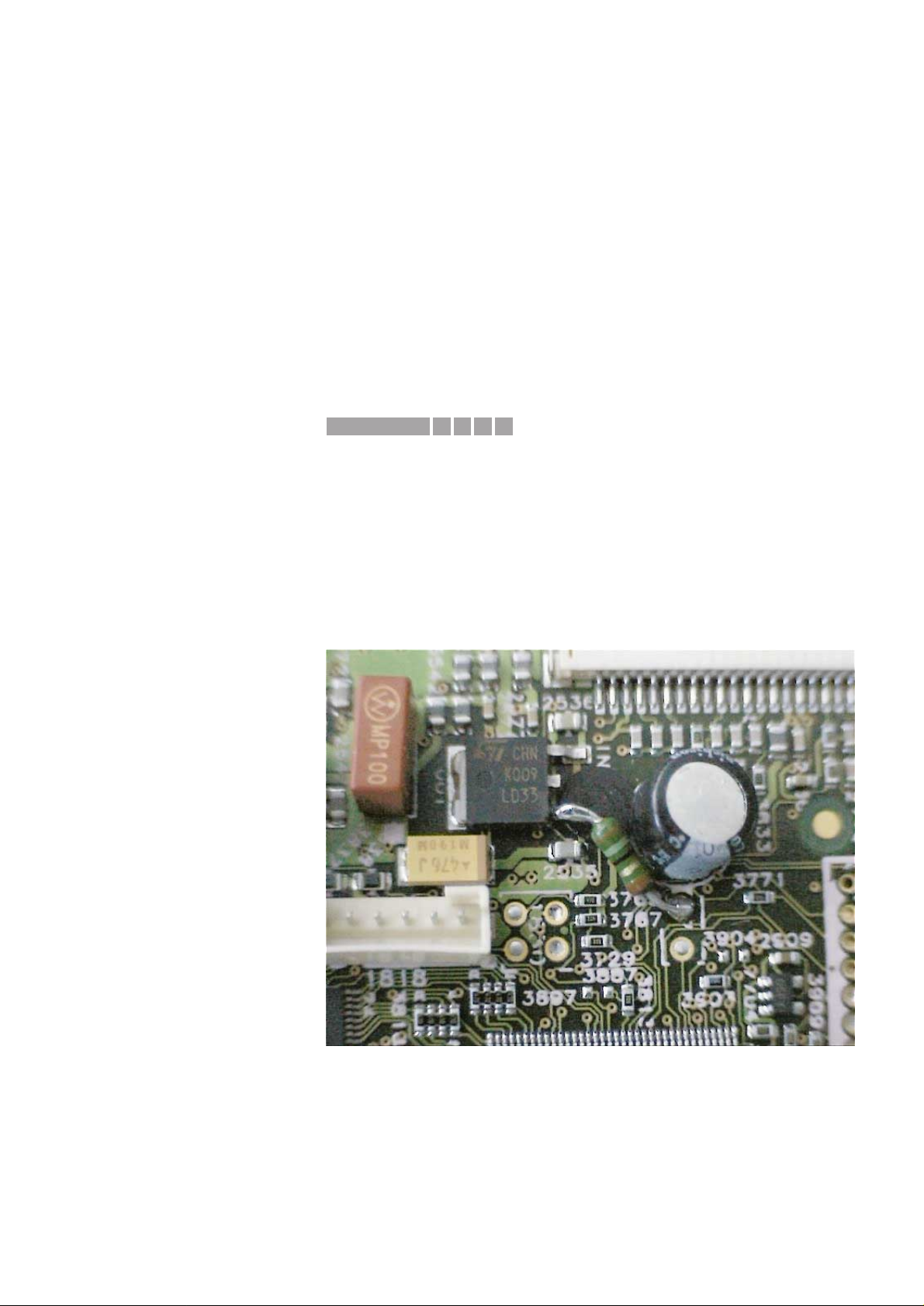
2. Software modification at the topside of the Main Board
• Update software version of item 7208 (in socket) to version 92.01.
Programmed flash with version 92.01 or higher can be ordered with
codenumber 3104 123 94850.
• Update software version of item 7703 (soldered) to version 1.51.
Programmed flash with version 1.51 or higher can be ordered with
codenumber 3104 123 85760.
REMARKS : Software versions lower than 1.43 & 91.91 which have been updated
to the latest version must always be re-adjusted with the
COMP AIR T ool.Workshops which do not use COMPAIR have to
replace these 3rd generation CDR-modules.
See also Service Newsletter SNL2000.07.08.
07.13 TYPENUMBER(S): CDR570, CDR770, CDR775, CDR776, CDR930, CDR950, CDR951
SYMPTOM :
Clock jitter in DASP-IC item 7701 on CDR Mainboard, this can result
in hang-up of the microprocessor.After Power off, Power on the set
will normally star t but the phenomenon might return again.
CURE : To solve this problem in running production and as service solution,
the power supply of D3V3 has been improved by adding a resistor of
27Ω (CRB 1/6W A PM5 and order number 4822 116 52188) between
“disconnected” pin 1 of item 7535 and mass (hole 2 of item 1701).
See part of the main board (top side view) for location of the resistor.
REMARKS : With release of the A9 version of CDR Mainboard this resistor is
implemented in printed board layout and mounted in production.
1652IRIS CODE
Service Newsletter 2000 – BCU Audio 6/10
Page 14

07.14 TYPENUMBER(S): CDR570, CDR770, CDR775, CDR776, CDR930, CDR950, CDR951
INFORMATION : All returned discs, causing complaints on the CDR sets of the 3rd
generation, have been investigated. This results in the following
conclusion:
The Philips Megalife disc has been produced by Ricoh and Mitsui.
Most of the problems have been found with discs produced by Mitsui.
How to recognize the production centre?
Ricoh : made in USA printed on the jewel box
Mitsui : made in Europe printed on the jewel box.
Please note: Discs packed in a carton box (5pcs/carton) are
marked with made in USA!
Ricoh : Marked Audio HR100
Mitsui : Marked Audio100
Ricoh : serial number on inner circle consists of 4 character + 12
digits (e.g. ALXH 06109902214 3)
Mitsui : serial number on inner circle consists of 12 digits
(e.g. 9287 2217 4953)
It is not advised to apply the Mitsui disc in 3rd generation CDR
recorders up to software version 1.51.
REMARKS :
07.15 TYPENUMBER(S): CDR785, CDR786
INFORMATION : The sets are equipped with a special DEALER MODE.
This mode blocks the trays of the CDC- and CDR module to prevent
customers from fetching out CDs from exhibition sets.
The dealer mode can be switched on/off as follows:
1) Switch the set with the Remote Control to standby mode
2) Press the [DISPLAY] key for longer than 5s
→ Display shows
“DEALER MODE ON”
respectively
“DEALER MODE OFF”
REMARKS :
07.16 TYPENUMBER(S): CDR785, CDR786
INFORMATION : On the black versions CDR785/00 and CDR785/17 the feet pos. 22
have been changed from silver to anthracite metallic.
The codenumbers read as follows:
old: 4822 462 42159 foot silver
new: 4822 462 11174 foot anthracite metallic
REMARKS : The modification has been implemented in production from week
0032 onwards.
Service Newsletter 2000 – BCU Audio 7/10
Page 15
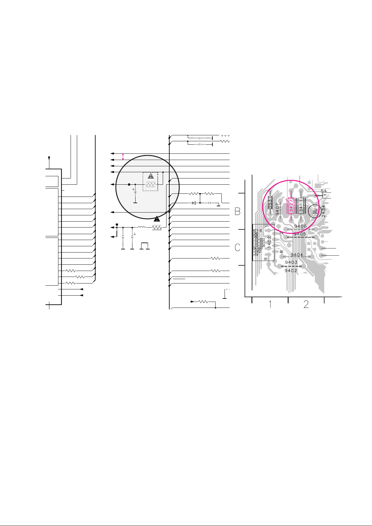
07.17 TYPENUMBER(S): CDR785, CDR786
INFORMATION : Production started with the OTP-version “TMP88PU77F”of the
microprocessor.
Service will deliver final mask version “TMP88CU77F-CDR785.2”
(3103 308 84170).
In case an OTP-version has to be replaced by the mask version
resistor 3427 has to be removed.
Reason:The mask version has an internal connection between the
supply pins 32 (+µP) and 51 (+D).
REMARKS :
07.18 TYPENUMBER(S): EXP101, EXP103
INFORMATION : Following components have been changed to improve the CD start-
up and EMC behaviour:
RP36 changed from 47kΩ to 100kΩ (4822 117 13632)
RM87 and RM88 changed from 100Ω to 330Ω (4822 051 10331)
RD28, RD29 and RD30 changed from 100Ω to 1kΩ
(4822 051 30102)
RD41, RD42 and RD43 changed from 22Ω to 1kΩ (4822 051 30102)
REMARKS : Modifications are implemented since production start.
copperside view
P7
P6
+
-
+
+
SUPP
2416
330p
100u
2434
D
D
3479
100R
F403
D
3460
470R
3503
1K
5407
2u2
10p2411
100R
3476
31
VASS
30
VDD-I|O
32
VDD-VFT
51
9
VAREF
P70
41
P71
42
43
P72
P73
44
P74
45
P75
46
P76
47
P77
48
P80
49
P81
50
2
P60
33
P61
34
P62
35
P63
36
P64
37
P65
38
P66
39
P67
40
D
1N4148
6404
2432
47u
D
2R2
3411
D
270R
3518
100R
3482
10p2412
D
94
D
2K7
3451
270R
3516
100n
2431
3441 1K
F409
+5VST
+5V
+yP
+C
FAN
+F
CWReset
KEY0
AnaSw0
AnaSw2
SPLY_ON1
SPLY_ON2
+C
I2CW_DATA
I2CW_CLK
MUTE
AnaSw1
DigSw2
DigSw1
G7
G3
G15
G14
G13
G1
G5
G6
DigSw0
G10
G12
G9
P2
P2
G11
+D
-F
-30V
G8
G4
G2
+yP
+D
CDSwInfo
CWReqKbe
+C
4R7
3427
for OTP version
of µP only
to be removed
if mask version
of µP is used
5V typ.
5V
-8,
0/5
4,1V +/- 0,4V
-29,3V +/- 2,2V
5V +/- 0,25V
3,2V
5V
4,9V
3,7/3
5V +/- 0,25V
5V typ.
5V
4,4V
0/5
0/5
0/5
0/5
CD/C
4,9V
5V
Service Newsletter 2000 – BCU Audio 8/10
Page 16

07.19 TYPENUMBER(S) : FW-C1, FW-C3, FW-C10, FW-C30, FW-C-35
SYMPTOM :
After record, there is no (or wrong) output when playing back the
tape.
CURE : Replace the Erase Head if there is no oscillation at jumper 9730 (test
point 5) although the erase oscillator is working normally (no
defective components).
REMARKS : The problem is caused by a poor batch of Erase Heads.
It is resolved from production week 0009 onwards.
07.20 TYPENUMBER(S) : FW-C1, FW-C3, FW-C10, FW-C28, FW-C30, FW-C35, FW-C38,
FW-C39, FW-C40, FW350C, FW390C, FW391C, FW396C, FW398C,
FW540C, FW545C, FW548C, FW555C, FW585C, FW590C,
FW595C, FW748P, FW768P, FW798W, FW830C, FW840C, FW870C,
FW878C, FW890P, FW898W, FW910R, FW930, MZ7
INFORMATION : Correction to Service Manual, Mechanical Partslist 3CDC99 module
Some of the published codenumbers are wrong.
Pos no. Description should read
––––––––––––––––––––––––––––––––––––––––––
3 Guiding left 4822 463 11235
4 Guiding right 4822 463 11236
12 Rubber 4822 446 12146
13 Rubber 4822 446 12146
21 Drawer 3104 304 66800
22 Bracket Tumbler 4822 402 11236
23 Spring 4822 492 11721
40 Slide 4822 463 11237
115 Carousel 3103 304 66810
REMARKS :
07.21 TYPENUMBER(S): FW-C10/21
INFORMATION : Correction to the Service Manual, Partslist
The codenumber for the Mains transformer 5001 should read
4822 146 10956.
REMARKS :
X652IRIS CODE
Service Newsletter 2000 – BCU Audio 9/10
Page 17

07.22 TYPENUMBER(S): FW-R7, FW-R8
INFORMATION : The sets are equipped with a special DEALER MODE.
This mode blocks the trays of the CDC- and CDR module to prevent
customers from fetching out CDs from exhibition sets.
The dealer mode can be switched on/off as follows:
1) Switch the set with the stanby-button to standby mode
2) Press the [DISPLAY] key for longer than 5s
→ Display shows “
DEALER MODE ON“
respectively
“
DEALER MODE OFF“
REMARKS :
Service Newsletter 2000 – BCU Audio 10/10
Page 18

For internal use only PHILIPS
ISSUE SNL2000.06 (00-07-06)
Published by:
Service Depar tment Audio
BUSINESS CREATION UNIT AUDIO
06.01 TYPENUMBER(S): AQ5460
SYMPTOM :
Hiss is audible on recordings.
CURE : Phenomenon is caused by unstability of the bias oscillator.
Change resistor 3732 from 10Ω to 15Ω (4822 116 52182).
REMARKS : Modification has been implemented in production from week 0014
onwards.
06.02 TYPENUMBER(S): AZ1030, AZ1035
INFORMATION : To solve the problem
“skips tracks due to acoustic feedback”
the CDclamper assembly (items 428, 429 and 431) has been replaced by
the new clamper assembly (3140 117 59800) .
REMARKS : New CD-clamper assemblies are used in production from week 0024
onwards.
06.03 TYPENUMBER(S): AZ1040, AZ1045, AZ1120
INFORMATION : To solve the problem
“skips tracks due to acoustic feedback”
the CDclamper assembly (items 436, 437 and 438) has been replaced by
the new clamper assembly (3140 117 59800) .
REMARKS : New CD-clamper assemblies are used in production from week 0024
onwards.
06.04 TYPENUMBER(S): AZ1040, AZ1045, AZ1550, AZ1560, AZ1565
SYMPTOM :
Hiss is audible on recordings.
CURE : Phenomenon is caused by unstability of the bias oscillator.
Change resistor 3732 from 10Ω to 15Ω (4822 116 52182).
REMARKS : Modification has been implemented in production from week 0014
onwards.
2451IRIS CODE
2451IRIS CODE
SERVICE NEWSLETTER
Service Newsletter 2000 – BCU Audio 1/3
Page 19

06.05 TYPENUMBER(S): AZ1045
INFORMATION : During production, the IR receiver 7407 has been changed from
TSOP2836 (9322 139 51667) to TSOP2236 (9322 155 82667).
The electronic circuit has been adapted by changing 3451 from
470kΩ to 330kΩ (4822 051 20334).
REMARKS : Modification has been implemented in production from week 0024
onwards.
06.06 TYPENUMBER(S): AZ1550, AZ1560, AZ1565
INFORMATION : To solve the problem
“skips tracks due to acoustic feedback”
the CDclamper assembly (items 443, 444 and 446) has been replaced by
the new clamper assembly (3140 117 59800) .
REMARKS : New CD-clamper assemblies are used in production from week 0024
onwards.
06.07 TYPENUMBER(S): FW399V,FW548V
SYMPTOM :
Interruptions during playing a VCD when singing along a session on
Karaoke.
CURE : The problem is due to high acoustic feedback (high volume) into the
main unit via the adjacent loudspeakers.
Place the loudspeaker boxes at least 60cm away from the main unit
or place a rubber mat (size: 26cm x 30cm, thickness: ≥8mm) below
the main unit to absorb any acoustic vibrations.
REMARKS :
06.08 TYPENUMBER(S): FW399V,FW548V
SYMPTOM :
The first piece of new tracks is skipped when playing a
NON-STOP Audio CD.
CURE : The momentary music break between tracks is caused by the
software.When there is no Pause recorded on the disc and a new
track is recognized the software automatically mutes for a few
seconds.
The problem is solved with the new MPEG software version_13 for
IC 7202 on the MPEG board.
The new OTP is available under service code: 9965 000 02715.
REMARKS :
X151IRIS CODE
X551IRIS CODE
Service Newsletter 2000 – BCU Audio 2/3
Page 20

06.09 TYPENUMBER(S): MC118, MC148
INFORMATION : To solve the problem
“skips tracks due to acoustic feedback”
the CDclamper assembly (items 437, 438 and 439) has been replaced by
the new clamper assembly (3140 117 59800).
REMARKS : New CD-clamper assemblies are used in production from week 0024
onwards.
06.10 TYPENUMBER(S): SD100/01M
INFORMATION : Some of the service code numbers published in the Service Manual
(page 1-1) are stated wrong.The correct code numbers are as
follows:
Pos Service code Ar ticle descr iption
–––––––––––––––––––––––––––––––––––––––––––
200 3141 017 72470 Front Cabinet Assembly
203 3141 017 72500 Play Button
206 3141 017 72340 Power Button
208 3141 014 23550 Volume Knob
209 3141 017 72480 Cover, Window
233 3141 017 72490 Cover, CD Tray
REMARKS :
Service Newsletter 2000 – BCU Audio 3/3
Page 21

For internal use only PHILIPS
ISSUE SNL2000.05 (00-06-09)
Published by:
Service Depar tment Audio
BUSINESS CREATION UNIT AUDIO
05.01 TYPENUMBER(S): AJ3935
SYMPTOM :
Transformer hum is audible.
CURE : The hum is caused by vibration of the metal transfor mer bracket (item
502). For service pur pose the metal bracket can be removed without
substitution.
REMARKS : In production, a rubber foam of 20 x 25 x 26 mm will be placed
between top of transformer and Top Cabinet (item 427).
This will protect the printed board from being damaged during transit.
The modification has been implemented in production from week
0014 onwards.
05.02 TYPENUMBER(S): AZ1005, AZ1007
INFORMATION : Due to supply shortfall of servo IC TDA7073A, the CD module had to
be redesigned for IC TCA0372DP1. The new modules are used in
production alternatively.
For repair infor mation on new CD modules see Service Information
A00-551 (3140 785 22310).
REMARKS : Alternative CD modules are used in production from week 0013
onwards.
05.03 TYPENUMBER(S): AZ1100, AZ1101, AZ1102, AZ1103, AZ1104
INFORMATION : Due to supply shortfall of servo IC TDA7073A, the CD module had to
be redesigned for IC TCA0372DP1. The new modules are used in
production alternatively.
For repair infor mation on new CD modules see Service Information
A00-552 (3140 785 22320).
REMARKS : Alternative CD modules are used in production from week 0013
onwards.
4412IRIS CODE
SERVICE NEWSLETTER
Service Newsletter 2000 – BCU Audio 1/4
Page 22

05.04 TYPENUMBER(S): AZ1110, AZ1111, AZ1112, AZ1113, AZ1114
INFORMATION : Due to supply shortfall of servo IC TDA7073A, the CD module had to
be redesigned for IC TCA0372DP1. The new modules are used in
production alternatively.
For repair infor mation on new CD modules see Service Information
A00-553 (3140 785 22330).
REMARKS : Alternative CD modules are used in production from week 0013
onwards.
05.05 TYPENUMBER(S): AZ1116, AZ1117, AZ1118, AZ1119
INFORMATION : Due to supply shortfall of servo IC TDA7073A, the CD module had to
be redesigned for IC TCA0372DP1. The new modules are used in
production alternatively.
For repair infor mation on new CD modules see Service Information
A00-555 (3140 785 22360).
REMARKS : Alternative CD modules are used in production from week 0013
onwards.
05.06 TYPENUMBER(S): AZ2750, AZ2755
INFORMATION : Due to supply shortfall of servo IC TDA7073A, the CD module had to
be redesigned for IC TCA0372DP1. The new modules are used in
production alternatively.
For repair infor mation on new CD modules see Service Information
A00-554 (3140 785 22340).
REMARKS : Alternative CD modules are used in production from week 0014
onwards.
Service Newsletter 2000 – BCU Audio 2/4
Page 23
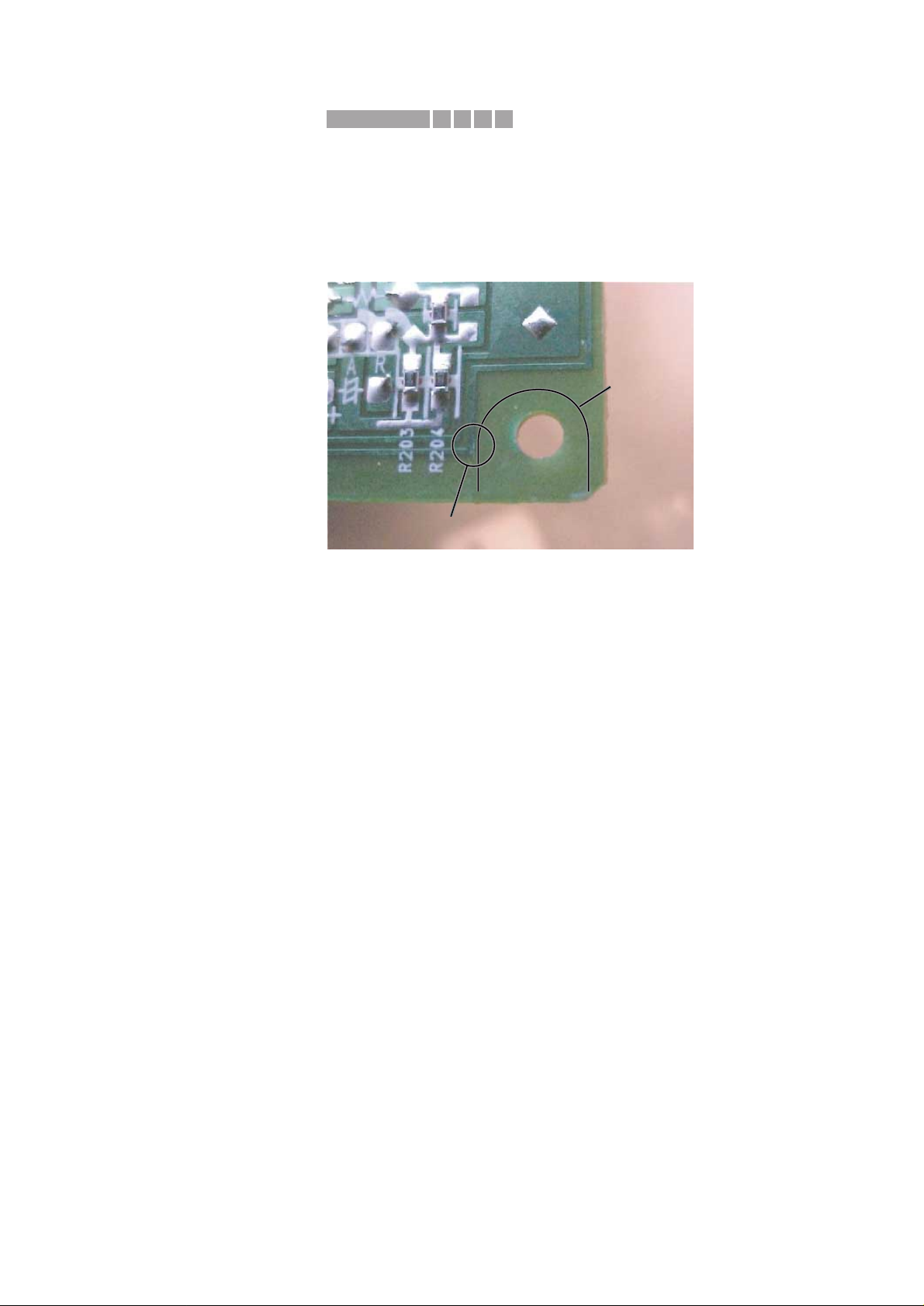
05.07 TYPENUMBER(S): CDR785/17
SYMPTOM :
The Standby-LED is inoperative.
The power consumption in standby is higher than specified and close
to the power consumption is STOP-mode.
CURE : The problem is caused by the fishplate supporting the Power Supply
Unit. In some cases the fishplate can touch a copper track of the
Power Board close to resistor R204 (see picture below).
This will short-circuit par ts of the power supply circuitry to the ground
potential of the bottom frame.
As a result, the display will switch off, but the LED does not light.
Solution: Place an insulating layer (i.e. friction tape or piece of Fuller
board) between printed board and holder.
REMARKS : The green protection lacquer on the printed board normally ensures
proper insulation of copper tracks.However, due to transportation or
rough handling, the critical area can get exposed.
In production, the bottom frame has been modified.
The modified parts are used from week 0020.4 onwards.
05.08 TYPENUMBER(S): FW830C, FW840C, FW870C, FW878C, FW890P, FW898W
INFORMATION : Additional information to Service Newsletter items AS99.08.03 and
AS99.10.02:
The reliability of EEPROM data can be improved further by changing
the value of resistor 3611 to 2.2kΩ 5% 0.1W (4822 117 11449).
REMARKS :
05.09 TYPENUMBER(S): MC118
INFORMATION : Correction to Service Manual, partslist
The codenumber of the CD Door Switch (item 1025) is missing.
The switch is available with codenumber 4822 276 13963.
REMARKS :
short-circuit in this area
shape of
fishplate
X111IRIS CODE
Service Newsletter 2000 – BCU Audio 3/4
Page 24

05.10 TYPENUMBER(S): MZ-3, MZ-33
SYMPTOM :
No sound output, resistor 3363 is blown.
CURE : • Change resistor 3363 from 22Ω to a 10Ω NFR-type
(4822 052 11109)
• Change capacitor 2362 from 100µF to 22µF (4822 124 81151)
REMARKS : The modification has been implemented in production from week
0018 onwards.
0156IRIS CODE
Service Newsletter 2000 – BCU Audio 4/4
Page 25

For internal use only PHILIPS
ISSUE SNL2000.04 (00-05-05)
Published by:
Service Depar tment Audio
BUSINESS CREATION UNIT AUDIO
04.01 TYPENUMBER(S): CD713, CD723, CD753
SYMPTOM :
The set does not recognize CD-R/CD-RW discs with extremely high
jitter value (i.e.high-speed recordings from computer-CD-Writers).
CURE : The problem can be solved by the following modification on the
CD-SL Mk3 Board:
• Remove resistor 3806
• Remove capacitor 2810
REMARKS :
04.02 TYPENUMBER(S): CDR570, CDR770, CDR775, CDR930, CDR950
INFORMATION : Additional information to the 2nd line Service Manual CDR570,
CDR770, CDR775, CDR930, CDR950 (3104 125 40110).
CDR Main Board, Circuit Diagram 6:
In course of production, fuse resistors 3411 and 3439 (4R7) have
been replaced by coils.
Pos Codenumber Article description
–––––––––––––––––––––––––––––––––––––
3411 4822 157 11717 COIL 50µH
3439 4822 157 11717 COIL 50µH
REMARKS : The modification will improve the temperature behaviour.
415CIRIS CODE
SERVICE NEWSLETTER
Service Newsletter 2000 – BCU Audio 1/2
Page 26
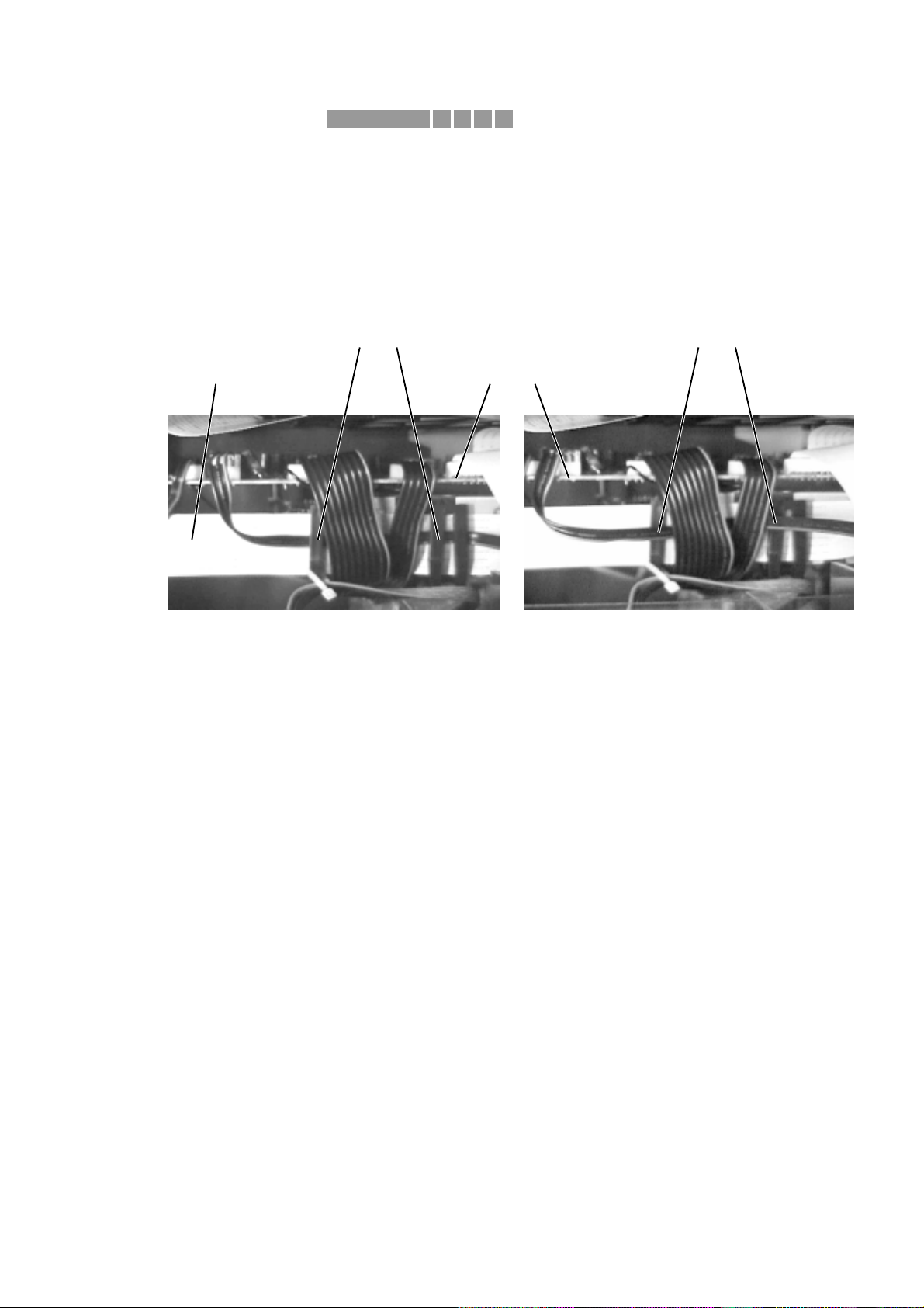
04.03 TYPENUMBER(S): FW-P73, FW-P75
SYMPTOM :
Ticking sound (similar to that of a clock) is audible from the center
speaker during quiet portions of music.
CURE : The problem is caused by crosstalk from flex-cable 1681 to wire
1572.
The problem can be solved by routing wire 1572 outside the wire
catches of flex-cable 1572 as shown in the r ight picture below.
REMARKS :
flex-cable 1681 AF6-Board
wire 1572 placed inside
the cable catches
wire 1572 placed outside
the cable catches
fig.1 – wire position in a problem set fig.2 – wire position in a good set
4451IRIS CODE
Service Newsletter 2000 – BCU Audio 2/2
Page 27

For internal use only PHILIPS
ISSUE SNL2000.03 (00-04-06)
Published by:
Service Depar tment Audio
BUSINESS CREATION UNIT AUDIO
03.01 TYPENUMBER(S): AQ4150
SYMPTOM :
Poor recordings from Tuner (FM) on normal tape
(unstable output level).
CURE : • Change R8 from 15kΩ to 12kΩ (4822 116 51254)
• Change R14 from 2.2MΩ to 1.5MΩ (4822 050 21505)
• Change R18 from 820Ω to 390Ω (4822 050 28201)
• Change C11 from 0.22µF to 10µF (4822 124 40248)
• Change C21 from 0.22µF to 1µF (4822 124 40746)
REMARKS : Modification has been implemented in production from week 0010
onwards.
03.02 TYPENUMBER(S): AQ6455
INFORMATION : For environmental reasons the original motor “MMN-6S9RX” has
been replaced by “EG-530YD-9FH”.
The codenumber of the new motor reads:
9965 000 04407 Motor EG-530YD-9FH
REMARKS : The new motor is used in production from week 0013 onwards.
03.03 TYPENUMBER(S): AZ1116, AZ1117, AZ1118, AZ1119, AZ8084, AZ8085, AZ8086,
AZ8087
INFORMATION : Correction to the Service Manual, Mechanical Partslist
The codenumber of the DBB Knob (item 409) is wrong.
It should read 4822 410 12536.
REMARKS :
03.04 TYPENUMBER(S): AZ2750, AZ2755
INFORMATION : The codenumber of the CD Door Switch is missing.
The switch is available with codenumber 4822 276 13963.
REMARKS :
2352IRIS CODE
SERVICE NEWSLETTER
Service Newsletter 2000 – BCU Audio 1/5
Page 28
03.05 TYPENUMBER(S): AZ7894
INFORMATION : Correction to the Service Manual, Mechanical Partslist
The codenumber of the CD Door Assembly is wrong.
It should read 3140 119 02730.
REMARKS :
03.06 TYPENUMBER(S): AZ9899
SYMPTOM :
During Video CD playback the picture is frozen or skipping.
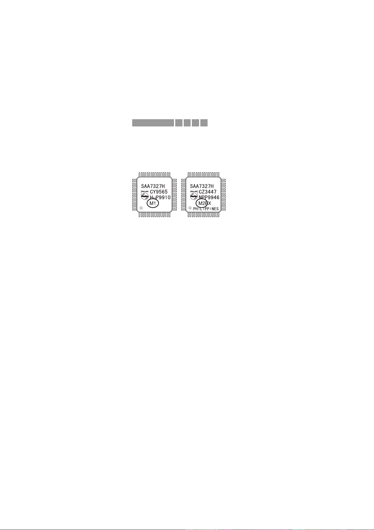
CURE : • Upgrade IC QD01 SAA7327H from version “M1” to version “M2BX”
(9352 616 71557)
• Change resistor RD39 from 22kΩ to 1kΩ (4822 051 30102)
REMARKS : Modification has been implemented in production from LOT 05
onwards.
03.07 TYPENUMBER(S): CD6660, D6560
INFORMATION : The impedance of the loudspeakers 1000 and 1001 has been
changed from 4Ω to 6Ω in order to reduce click noise at low
frequency.
The codenumbers of the new loudspeakers are:
1000 2422 264 00382 Woofer 6.5“
1001 2422 264 00383 Tweeter 2.5“
REMARKS : Modification has been implemented in production from week 0004
onwards.
The output power remains unchanged at AC supply mode.
03.08 TYPENUMBER(S): CDR200, CDR538, CDR560, CDR760, CDR765
INFORMATION : For price reasons the power supply service kit 3122 785 90130,
mentioned in Service Newsletter AS2000.02, will not be delivered.
Please order defective parts separately.
REMARKS :
A532IRIS CODE
Service Newsletter 2000 – BCU Audio 2/5
Page 29
03.09 TYPENUMBER(S): CDR570, CDR770, CDR930
SYMPTOM :
Stops during recording
Motor noise while recording CDR/W disc
CURE : Above problems can be solved by a hardware (1) and a software (2)
modification. Note that both changes must be implemented at the
same time.
1. Hardware modification at the topside of the main board
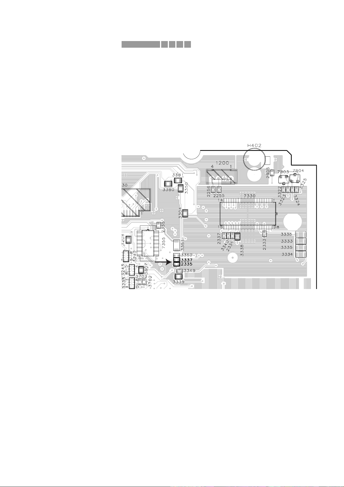
• Change item 2335 from 10nF to 47nF (3198 017 34730)
• Change item 3337 from 68kΩ to 56kΩ (4822 051 30563)
Portion of Main Board (top side) for location of 2335 / 3337
2. Software modification
• The software version of item 7208 at the topside (in socket) has to
be changed to version 91.80 or higher.
Programmed flash memory with version 91.80 can be ordered with
codenumber 3104 123 94850.
• The software version of item 7703 at the top side (soldered) has to
be changed to version R-1.34 or higher.
Programmed flash memory with version R-1.34 can be ordered with
codenumber 3104 123 85760.
X651IRIS CODE
Service Newsletter 2000 – BCU Audio 3/5
Page 30
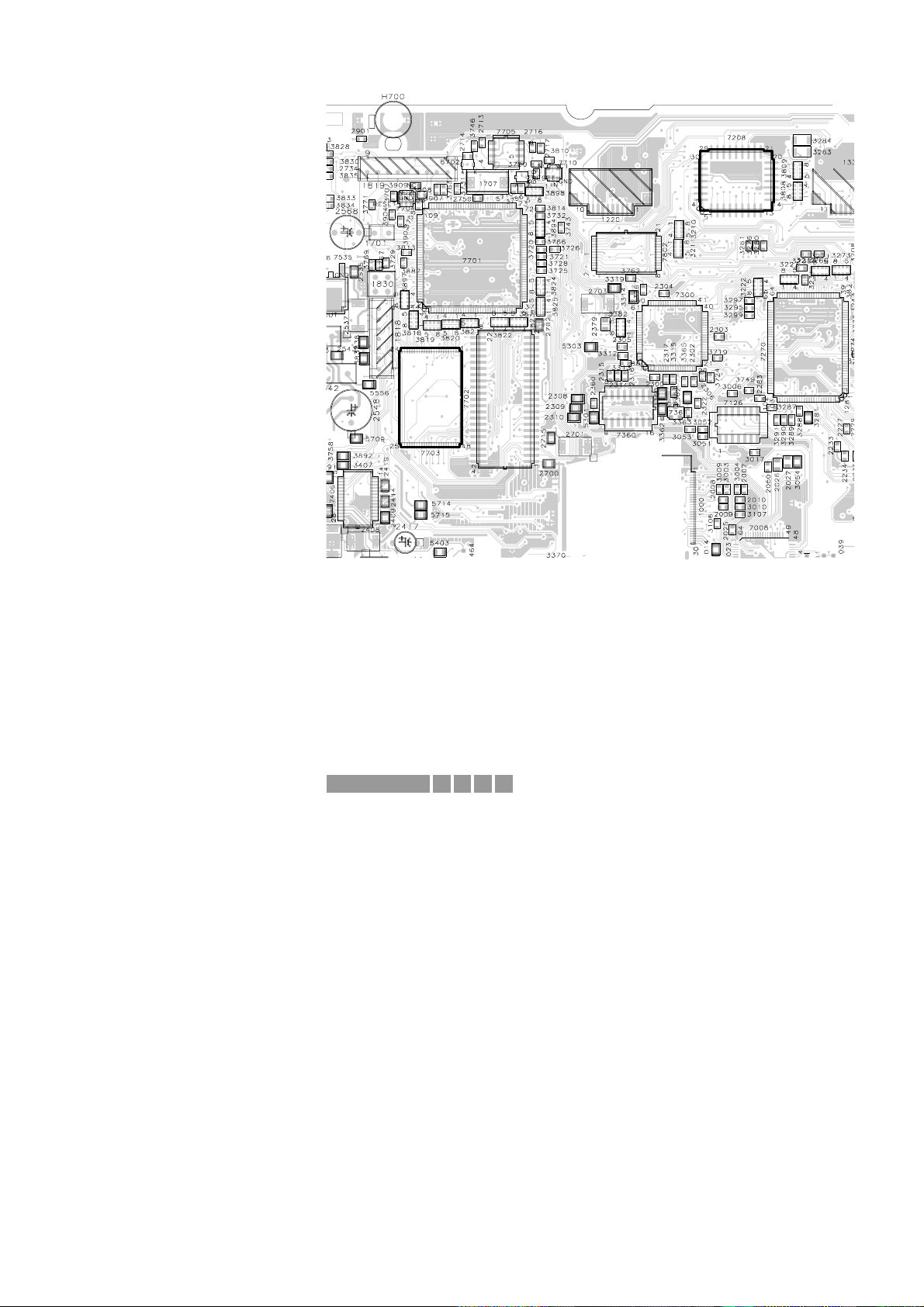
Portion of Main board for location of flash memories 7208 / 7703
REMARKS : The status of the main-board can be identified by the board label.
For board label F and lower :change 2335/3337, replace 7208/7703
For board label G : change 3337, replace 7208/7703
For board label H : replace 7208/7703
For board label I : no changes necessar y
03.10 TYPENUMBER(S): FW350C, FW396C, FW545C, FW548C, FW555C, FW585C, FW590C
SYMPTOM :
Skips tracks periodically or slide motor does not start-up at all.
CURE : In regions with high environmental pollution the problem might be
caused by erosion of the slide motor’s collector.
Erosion will permanently worsen the start-up behaviour of the slide
motor, up to an extent where the slide servo does not respond fast
enough to recover the track actuator from its outer position → tracks
will be skipped periodically.
Defective sets should be repaired as follows:
1. Replace CD-dr ive VAM2201 (4822 691 10772)
2. Increase the gain of the slide ser vo loop in order to increase the
start-up voltage at the slide motor (preventive action)
• Change resistor 3849 to 82kΩ 5% 1/6W (4822 116 52304)
• Change resistor 3850 to 5.6kΩ 5% 1/6W (4822 116 52289)
REMARKS :
X761IRIS CODE
7703
7208
Service Newsletter 2000 – BCU Audio 4/5
Page 31

03.11 TYPENUMBER(S): FW388V, FW399V, FW548V
INFORMATION : The Flex Foil Cable 15p, 19cm for connection between the Servo
Board connector 1805 and the Connector Board connector 1806 in
the 3-Video CD Module has been added to the partslist.
Pos Codenumber Article description
––––––––––––––––––––––––––––––––––––––––––––––
8002 4822 320 11974 Flex Foil Cable 15p, 19cm
REMARKS :
03.12 TYPENUMBER(S): FW748P, FW768P, FW798W, FW-P73, FW-P75, FW-P78
SYMPTOM :
DPL test tone is distorted (“motor-boating” & lower frequency).
CURE : The problem is caused by insufficient capacitor value at pin 1
(noise sequencer) of the DPL IC M62460FP.
It is solved by changing capacitor 2769 to 47µF 20% 25V
(4822 124 40433)
REMARKS :
03.13 TYPENUMBER(S): FW890P, FW898W
INFORMATION : Correction to Service Manual, Electrical Partslist page 11-12.
The article description of item 7930 should read:
4822 209 16166 STK407-040B
REMARKS :
03.14 TYPENUMBER(S): MC136
INFORMATION : Correction to the Service Manual, Mechanical Partslist
The codenumber of the Control Panel (item 52) is wrong.
It should read 4822 426 10655.
REMARKS :
03.15 TYPENUMBER(S): MC165, MC175
SYMPTOM :
The CD Tray cannot be closed and the display shows “BLOCK”.
CURE : The gears of the CD loader are out of coupling because of external
force or physical block of the tray during sliding out.
If it cannot be resumed, the gears must be re-aligned as shown on
page 14-2 of Service Manual 4722 725 26195 resp. 4822 725 26213.
REMARKS :
A562IRIS CODE
2351IRIS CODE
Service Newsletter 2000 – BCU Audio 5/5
Page 32

For internal use only PHILIPS
ISSUE AS2000.02 (00-02-10)
Published by:
Service Depar tment Audio Systems
LINE OF BUSINESS AUDIO SYSTEMS
02.01 TYPENUMBER(S): CDR200, CDR538, CDR560, CDR760, CDR765
INFORMATION : For repair of the power supply unit a special service kit containing the
mosts sensitive components has been created.
It can be ordered with service codenumber 3122 785 90130.
The service kit contains the following parts:
1120, 3109, 3113, 3126, 3127, 3128, 6113, 6210, 7110, 7125, 7200
REMARKS :
02.02 TYPENUMBER(S): CDR200, CDR538, CDR560, CDR760, CDR765
SYMPTOM :
Power supply is defective.
CURE : It is advised to repleace the following items:
• pos. 7125 (STP4 or STP3) by STP5
• pos. 6210 (PBYR745) by PBYR10100
REMARKS : For repair of the power supply unit a special service kit
3122 785 90130 is available (see 02.01 for details).
Items 6210 and 7125 can also be ordered separately:
Pos Codenumber Article description
—————————————————–————6210 9340 205 70127 PBYR10100
7125 9322 126 65687 STP5
1111IRIS CODE
SERVICE NEWSLETTER
Service Newsletter 2000 – Audio Systems 1/6
Page 33

02.03 TYPENUMBER(S): CDR200, CDR538, CDR560, CDR760, CDR765
SYMPTOM :
Short interruptions in recordings.
CURE : The problem is most probably caused by unstable operation of the
power supply. It is advised to repleace the following items:
• pos. 7125 (STP4 or STP3) by STP5
• pos. 6210 (PBYR745) by PBYR10100
REMARKS : For repair of the power supply unit a special service kit
3122 785 90130 is available (see 02.01 for details).
Items 6210 and 7125 can also be ordered separately:
Pos Codenumber Article description
—————————————————–————6210 9340 205 70127 PBYR10100
7125 9322 126 65687 STP5
02.04 TYPENUMBER(S): CDR770
INFORMATION : The correct codenumber for the complete (and adjusted)
CDR-Module reads 3104 129 52521.
For this module a central repair procedure has been initiated.
The loader assembly, pos. 81 in the par tslist (9305 043 20901),
cannot be used for repair because the CDL4009 needs an extra
adjustment on the mainboard which cannot be carried out on first
level.Please do not order these loaders, as they are reserved for the
central repairshop only.
REMARKS :
02.05 TYPENUMBER(S): FW-C1, FW-C3, FW-C10, FW-C30, FW-C35
SYMPTOM :
The cassette door will not open completely when a cassette is inside
the cassette compartment.
CURE : The capstan pin (pos. 41) of the tape mechanism will not disengage
fully from the cassette tape.The problem is caused by a combination
of the following:
a) Leaf springs (pos. 199) which are responsible to create a rotating
movement for the cassette during “door eject” are too weak to
push the cassette out of the capstan pin.
b) Mis-matched housing par ts of the cassette (see fig. 1) rub/scratch
against the support ribs of the cassette door (pos. 200).
c) Uneven cassette door support r ibs create an additional friction to
the rotating movement of the cassette.
X761IRIS CODE
6651IRIS CODE
Service Newsletter 2000 – Audio Systems 2/6
Page 34
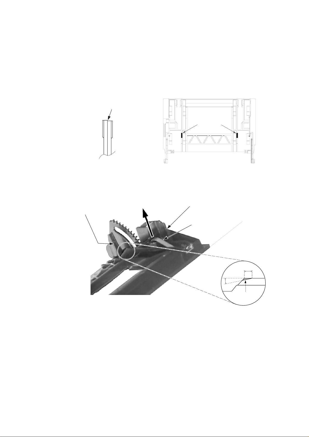
The problem is resolved by:
1) Cutting 2 ribs (both sides) on the cassette door in order to enable
a bigger rotational movement for the door during eject
(see figure 2 & 3).
2) Increasing the spring force on the cassette by pulling the spring in
the direction and up to the level shown in figure 3.
Caution: Ensure that the cassette is able to smoothly slide into the
cassette door before returning the set to the customer !
REMARKS :
3mm
Cut away this
shaded area
15
o
Figure 3. Portion of the Cassette door
Horizontal Line
Leaf Spring should not
be higher than this corner
of the cassette door
Cassette support
rib that is uneven
Pull Leaf Spring in
this direction
Problem Leaf
Spring
Mis-match cassette tape
housing (bare tape side)
Figure 1. Portion of Problem
Cassette Tape
Figure 2. Location of the ribs for rework
The 2 ribs that
must be cut lower
Service Newsletter 2000 – Audio Systems 3/6
Page 35
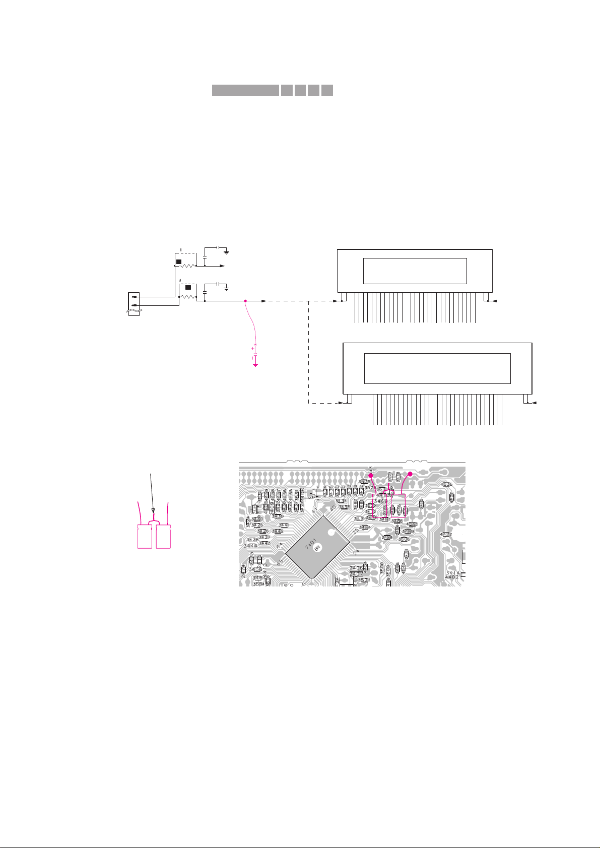
02.06 TYPENUMBER(S): FW-C1, FW-C3, FW-C10, FW-C28, FW-C30, FW-C35, FW-C38,
FW-C39
SYMPTOM :
A high frequency pitch (around 4kHz - 5kHz) is audible from the front
display panel in quiet environment.
CURE : The source of the noise comes from the filtering SMD capacitors
2418, 2420, 2476 and 2477.
The problem is resolved by adding 2 elcaps of 4,7µF
(4822 124 40769) in series across the existing SMDs capacitors of
the -F2 supply line.
The elcaps can by soldered onto the copperside of the Front board as
indicated in the circuit and SMD layout view below.
Rework procedure:
1) Dismantle the Cover CDC and Front assembly.
2) Prepare the 2 elcaps of 4,7µF (4822 124 40769) in ser ies.
3) Place an insulation tape onto the Front board (area under the
elcaps) to prevent the elcaps and their leads from short-circuiting
to the surrounding SMD components and pads.
4) Position the elcaps horizontally over the insulation tape and solder
them to the copper pads as shown.
Make sure that the elcaps are close to the Front board so that
there is no contact to the moving parts of the CDC module.
5) Re-assemble the Front assembly and Cover CDC.
REMARKS :
F1
F2
1R
3483
9522
9521
3471
1R
2476
1u
FTD
FTD
1u
2477
1401
15
16
1u
2418
8
P147P156P16
5
P0318P0417P0516P0615P0714P0813P0912P10
11
10
P119P12
P13
26
09G2510G2411G2312G
22
F1a1F1b
2
F2a39F2b
38
P0120P02
19
1400
BJ722GNK
01G3302G3203G3104G3005G
29
28
06G2707G
08G
2420
1u
F2
F1
F2
F1
12
P1511P16
10
23
P0422P0521P06
20
19
P07
P0818P0917P1016P1115P1214P1313P14
11G
30
29
12G2813G2714G
F1a1F1b
2
F2a49F2b
48
P0125P0224P03
1438
HN-14NN12T
01G4002G
39
38
03G
04G3705G3606G3507G3408G3309G3210G
31
F2 F1
Large FTD Display
Small FTD Display
FTD
4u7
4u7
-
-
+
+
Pre-prepared
elcos in series
Twist & soldered together
Portion of the Front Board (SMD side)
-
-
+
+
Portion of the Front Circuit
X411IRIS CODE
Service Newsletter 2000 – Audio Systems 4/6
Page 36
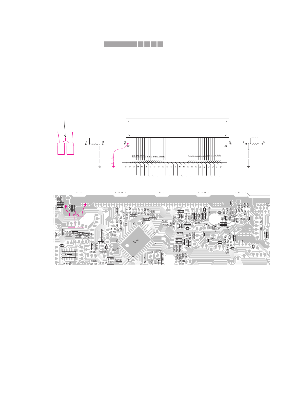
02.07 TYPENUMBER(S): FW-C50, FW-C55, FW-C58, FW-C70, FW-C71, FW-C72, FW-P73,
FW-P-75, FW-P78
SYMPTOM :
A high frequency pitch (around 4kHz - 5kHz) is audible from the front
display panel in quiet environment.
CURE : The source of the noise comes from the filtering SMD capacitors
2483 - 2486 for the FTD display supply -F1 and -F2.
The problem is resolved by adding 2 elcaps of 4,7µF
(4822 124 40769) in series across the existing SMDs capacitors of
the -F1 supply line.
The elcaps can by soldered onto the copperside of the Front board as
indicated in the circuit and SMD layout view below.
Rework procedure:
1) Dismantle the Rear Cover, Cover CDC and CDC Module.
2) Prepare the 2 elcaps of 4,7µF (4822 124 40769) in ser ies.
3) Place an insulation tape onto the Front board (area under the
elcaps) to prevent the elcaps and their leads from short-circuiting
to the surrounding SMD components and pads.
4) Position the elcaps horizontally over the insulation tape and solder
them to the copper pads as shown.
Make sure that the elcaps are close to the Front board so that
there is no contact to the moving parts of the CDC module.
5) Re-assemble the CDC Module, Cover CDC and Rear Cover.
REMARKS :
3430
3448
1u
2486
3438
3434
41 42 4344 45 46 47 48 5152 536 7 8 9 26 27 28293 30 3132 33 34 35 36 3738 39 4011 1213 14 15 16 17 18192 20212223 2425
1415
110
3446
3442
3447
D
1u
2483
3443
3451
3452
3431
3436
3439
3437
3435
2485
1u
D
1R
3560
3449
9401
3561
1R
3433
9400
3432
3444
3450
3440
3441
3445
3429
2484
1u
FTD Display
D
4u7
4u7
Portion of the Front Circuit
Portion of the Front Board (SMD side)
-
-
+
+
-
-
+
+
Pre-prepared
elcos in series
Twist & soldered together
X411IRIS CODE
Service Newsletter 2000 – Audio Systems 5/6
Page 37

02.08 TYPENUMBER(S): FW748P, FW-P73, FW-P75
SYMPTOM :
In DPL mode the volume increases spontaneously and turns back to
normal level later (especially at the center loudspeaker).
CURE : The problem is caused by insufficient current on the VOL_CLK
(DPL_V_CLK) line to drive pin 5 of the Volume IC 7712 M62429FP
on the AF board.
This is solved by changing resistor 3416 on the Front Board from
2,2kΩ to 680Ω (4822 117 10361).
REMARKS :
02.09 TYPENUMBER(S): SD100
INFORMATION : On special request the MPEG Board has been added to the service
parts list.
Pos Codenumber Article description
––—————————————————–————————1001 3141 018 01780 MPEG Board for SD100/00M
1001 3141 018 01890 MPEG Board for SD100/01M
REMARKS :
X25CIRIS CODE
Service Newsletter 2000 – Audio Systems 6/6
Page 38
For internal use only PHILIPS
ISSUE AS2000.01 (00-01-21)
Published by:
Service Depar tment Audio Systems
LINE OF BUSINESS AUDIO SYSTEMS
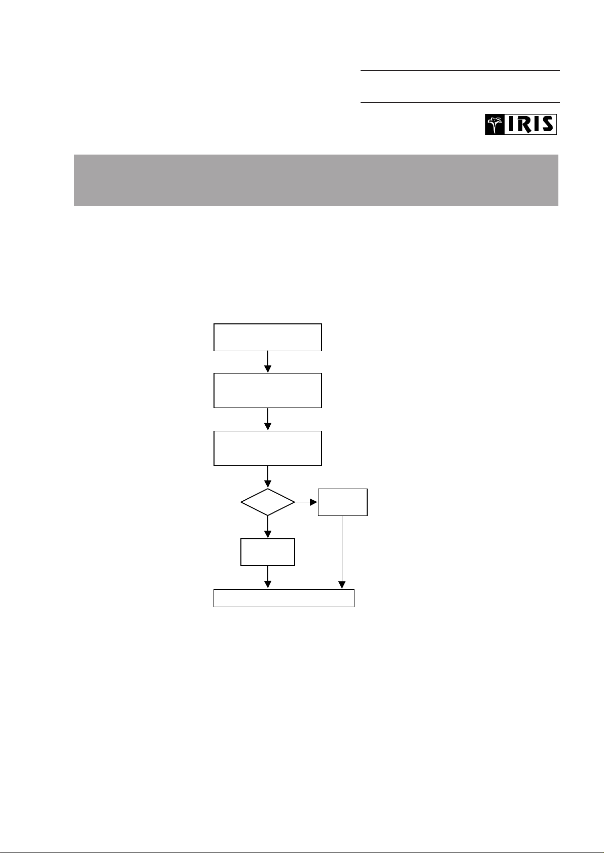
01.01 TYPENUMBER(S): CDR570, CDR930, CDR770
INFORMATION : Correction to the Service Manual, Dealer Diagnostics
Figure 6.1 is wrong.The correct buttons for entering the test are
“REWIND” + “FFWD” (instead of “PLAY” + “STOP”).
REMARKS :
01.02 TYPENUMBER(S): FW320C/21, FW380C/21, FW390C/21, FW545C/21, FW548C/21,
FW768P/21, FW870C/21, FW890P/21, FW898W/21
INFORMATION : The following part has been added to the service par ts list:
Pos Service code Article decription
––––––––––––––––––––––––––––––––––––––––––––––
386 4822 263 21092 ADAPTOR PLUG 6A 250V
REMARKS :
DEALER DIAGNOSTICS
(status of player)
Press <REWIND> + <FFWD>
simultaneously and switch
ON unit
If power ON,
switch power OFF
Set OK?
To end test, switch OFF unit
“
Set displays
PASSED
”
Display blinks
“BUSY”
during test
YES
NO
Set displays
“ERROR”
SERVICE NEWSLETTER
Service Newsletter 2000 – Audio Systems 1/3
Page 39
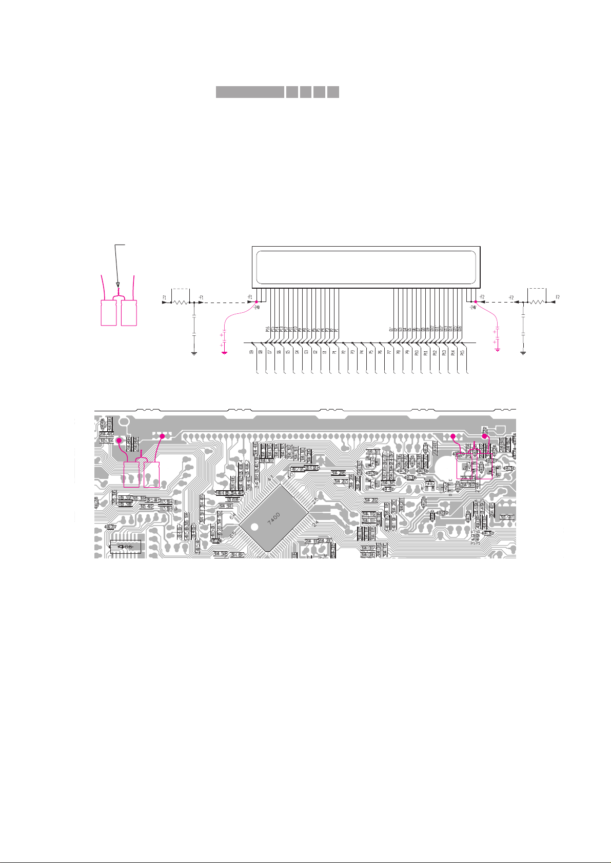
01.03 TYPENUMBER(S): FW540C, FW545C, FW548C, FW548V, FW555C, FW585C, FW590C,
FW595C, FW748P, FW768P, FW798W
SYMPTOM :
Digital hum (whistling tone) is audible from the display in quiet
environment.
CURE : The source of the noise comes from the filtering SMD capacitors
2483 - 2486 for the FTD display supply -F1 and -F2.
The problem is resolved by adding 2 x 2 elcaps of 4,7µF
(4822 124 40769) in series across the existing SMDs capacitors.
The capacitors can by soldered onto the copperside of the Front
board as indicated in the circuit and SMD layout view below.
Rework procedure:
1) Dismantle the Rear Cover, Cover CDC & CDC Module.
2) Prepare 2 sets of 2 x 4,7µF elcaps (4822 124 40769) in series.
3) Place an insulation tape onto the Front board (area under the
elcaps) to prevent the elcaps and their leads from short-circuiting
to the surrounding SMD components and pads.
4) Position the elcaps horizontally over the insulation tape and solder
them to the copper pads as shown.
Make sure that the elcaps are close to the Front board so that
there is no contact to the moving parts of the CDC module.
5) Re-assemble the CDC Module, Cover CDC and Rear Cover.
REMARKS :
3430
3448
1u
2486
3438
3434
41 42 4344 45 46 47 48 51 52 536 7 8 9 26 27 28293 30 3132 33 34 35 36 37 38 39 4011 1213 14 15 16 17 18 192 202122232425
1415
110
3446
3442
3447
D
1u
2483
3443
3451
3452
3431
3436
3439
3437
3435
2485
1u
D
1R
3560
3449
9401
3561
1R
3433
9400
3432
3444
3450
3440
3441
3445
3429
2484
1u
FTD Display
D
4u7
4u7
D
4u7
4u7
Portion of the Front Circuit
Portion of the Front Board (SMD side)
-
-
+
+
-
-
+
+
-
-
+
+
Pre-prepared
elcos in series
Twist & soldered together
X411IRIS CODE
Service Newsletter 2000 – Audio Systems 2/3
Page 40

01.04 TYPENUMBER(S): FW548V/21K, FW548V/21M
INFORMATION : The following part has been added to the service par ts list:
Pos Service code Article decription
––––––––––––––––––––––––––––––––––––––––––––––
1106 3139 118 77600 MODULE MPEG99 ECO
REMARKS :
01.05 TYPENUMBER(S): FW680V
INFORMATION : Correction to Service Manual, Electrical par tslist page 6-6
Codenumber for the microprocessor pos.7401 should read:
4822 209 13243 microprocessor not for /22
4822 209 13242 microrpocessor only for /22
REMARKS :
01.06 TYPENUMBER(S): FW830C, FW840C, FW870C, FW878C, FW890P, FW898W
INFORMATION : The following resistor has been changed on the front board to
improve the data reliability to the EEPROM:
3596 4822 117 12521 68Ω 1% 0,1W
REMARKS :
01.07 TYPENUMBER(S): FW830C, FW840C, FW870C, FW878C, FW890P, FW898W
SYMPTOM :
CD does not play and the display shows “DISC NOT FINALIZED”.
CURE : The problem happens mainly with Brazil’s Millennium disc and is
resolved by upgrading the software of the Front microprocessor IC
(pos. 7413) to version 20.
The service code for the new IC reads 9965 000 02901.
REMARKS :
01.08 TYPENUMBER(S): FW830C, FW840C, FW870C, FW878C, FW890P, FW898W
INFORMATION : Correction of Service Newsletter, item AS99.10.02
The correct buttons for entering the Service Test Progam are
“AUX” + “PRESET UP” instead of “AUX” + “PLAY”.
REMARKS :
415CIRIS CODE
Service Newsletter 2000 – Audio Systems 3/3
 Loading...