

Page 1

For internal use only PHILIPS
ISSUE PA97.06 (97-11-26)
Published by:
Service Depar tment LOBPA Hong Kong
LINE OF BUSINESS PORTABLE AUDIO
06.01 TYPENUMBER(S): AE3350
SYMPTOM : Batteries run out quickly.
CURE : A transistor (Q7) and a resistor 1kΩ (R17) were added since week
9636 to protect the audio IC from wrong polarity of external DC
supply.
The grounding end of R17 is wrongly connected to the ground before
the power switch, so that a current of 2.5mA is drawn in the power
“OFF” condition.
To solve the problem, remove R17 and connect a 1kΩ resistor from
the base of Q7 to the negative (-) of C43.
REMARKS : Modification has been implemented in production from week 9745
onwards.
06.02 TYPENUMBER(S): AW7150, AW7250
INFORMATION : For AW7150/11P and AW7250/11P only:
The tuning capacitor 2101 was replaced by 4822 125 11104.
To obtain optimum alignment, following components were changed to:
2116 5322 122 34107 3.9pF ±0.5pF N470
2124 4822 126 14267 3.3pF ±0.5pF N3300
REMARKS : Changes have been implemented in production from week 9723
onwards.
06.03 TYPENUMBER(S): AZ1100, AZ1101, AZ1102, AZ1103, AZ1104, AZ1105, AZ1106
INFORMATION : Correction to Service Manual, mechanical par tslist:
Item 33 is no service ar ticle.
Codenumber 4822 526 10625 refers to item 35.
35 4822 526 10625 magnet ring
REMARKS :
SERVICE NEWSLETTER
Service Newsletter 1997 – Portable Audio 1/3
Page 2

06.05 TYPENUMBER(S): AZ1100, AZ1101, AZ1102, AZ1103, AZ1104, AZ1105, AZ1106
INFORMATION : From October 1997 onwards, the CD main board was replaced by
“CD97 module”. In combination also a new Front Board and an
additional Regulation Board were implemented.
For details see Service Information A97-589 (4822 725 25647).
REMARKS : Sets with “CD97 module” can be identified by the factory change
code starting from KZ049740... onwards.
06.06 TYPENUMBER(S): AZ1202, AZ1602
SYMPTOM : The system hangs up when switching from TUNER- or TAPE-mode to
CD-mode.
CURE : To eliminate the noise level add capacitor 1nF/50V (4822 122 33197)
from pin 23 of 7401 to ground on front board.
REMARKS : Modification has been implemented in production from week 9740
onwards.
06.07 TYPENUMBER(S): AZ1302, AZ1307, AZ1308, AZ1402, AZ1407, AZ1508, AZ1509,
AZ2415, AZ2804, AZ2805, AZ2808
INFORMATION : From October 1997 onwards, the CD-drive (item 1800) of the “Short
Loader module” was changed from CDM12.1 to VAM1201 (4822 691
10615). In combination with VAM1201 the Clamper Assy (item 212)
has been changed to 4822 401 11709.
REMARKS : Short Loader modules with VAM1201 can be identified by the type
plate located on the rear side of the module.
VAM1201 is used from factory change code KT02 onwards.
06.08 TYPENUMBER(S): AZ1308
INFORMATION : For AZ1308/11 (FM/SW1/SW2/MW version) only:
In course of production the tuning capacitor 2101 was replaced by
4822 125 11104.
To obtain optimum alignment, following components were changed to:
2116 4822 126 14266 1pF ±0.25pF N470
2124 4822 126 14267 3.3pF ±0.5pF N3300
REMARKS : Changes have been implemented in production from week 9750
onwards.
Service Newsletter 1997 – Portable Audio 2/3
Page 3

06.09 TYPENUMBER(S): AZ2100, AZ2600, AZ2605, AZ2615
INFORMATION : For sets with factory change code KT02, which indicates new “CD5”
or “CD6” CD modules, resistors 3847 and 3848 were changed from
22kΩ to 33kΩ (4822 116 52271) in order to solve the start up
problem for 3“ skew disc.
REMARKS : Modification has been implemented in production from week 9742
onwards.
06.10 TYPENUMBER(S): AZ2305
INFORMATION : For radio alignment, the location of trimming capacitors C1, C2, C3
and C4 is not indicated on the layout diagrams in service manual.
For additional information see Service Information A97-587
(4822 725 25645).
REMARKS :
06.11 TYPENUMBER(S): AZ2605, AZ2615
INFORMATION : Item 7812, the remote control sensor TFMS5360 (4822 212 30842)
has been replaced by TSOP1736 (4822 218 11745).
REMARKS : The new remote control sensor has been implemented in production
from week 9740 onwards.The new sensor can be used without
further modification.
06.12 TYPENUMBER(S): AZ6880
INFORMATION : Correction to Service Manual, Electrical par tslist:
The service code number of Q421, 74HC4052 should read
5322 209 15779.
REMARKS :
06.13 TYPENUMBER(S): AZ7260, AZ7261, AZ7263, AZ7264, AZ7265, AZ7265, AZ7266,
AZ7267, AZ7268, AZ7271, AZ7272, AZ7275, AZ7278
INFORMATION : Above mentioned sets cannot charge ordinary loose NiCd batteries.
Only the Philips battery pack AY3361 (4822 138 10615) can be
charged.
REMARKS : The battery pack is charged via a separate charging pin, connected
to the exposed negative terminal of AY3361. On ordinar y loose NiCd
batteries the negative terminal is insulated and thus charging cannot
work.
Service Newsletter 1997 – Portable Audio 3/3
Page 4

For internal use only PHILIPS
ISSUE PA97.05 (97-10-01)
Published by:
Service Depar tment LOBPA Hong Kong
LINE OF BUSINESS PORTABLE AUDIO
05.01 TYPENUMBER(S): AJ3720, AJ3740
INFORMATION : Due to a software problem, the Alarm 2 does not function on Radio
preset 1. An addendum sheet is added to notify customers.
The message is as follows:
“In the radio wake-up alarm mode, the PRESET 1 station operates on
ALARM 1 only and not ALARM 2.”
REMARKS : Microprocessor IC with modified software will be implemented in
production from week 9748 onwards.
05.02 TYPENUMBER(S): AQ4050, AQ4150
INFORMATION : New tape deck was used in production.
Please refer following different service codenumbers:
4822 358 10233 Main belt
4822 528 70849 Pinch Roller Arm
4822 528 70695 Pinch Roller
4822 403 70968 Eject Slider
REMARKS : Modification was implemented in production from August 97 onwards
(factory code starting from KZ019734.. onwards).
05.03 TYPENUMBER(S): AZ1202, AZ1209
INFORMATION : Correction Service Manual, Mechanical par tslist:
The service codenumber of the CD-drive (item 454) on the exploded
view diagram is missing.It should read 4822 691 10587.
The motors of the CD-drive have been changed to type RF-310T.
The service codenumber of the new drive reads 4822 691 10654.
Only new drives will be delivered.
In order to optimize the playability of the new CD-drive, following
components on the CD97 board have also been changed:
2820 4822 121 51399 47nF 10% 50V
3855 4822 116 52271 33kΩ 5% 0.16W
REMARKS : Modification is implemented in production from week 9741 onwards.
For service purpose above mentioned components need not to be
exchanged when replacing an old drive by a new one.
SERVICE NEWSLETTER
Service Newsletter 1997 – Portable Audio 1/3
Page 5

05.04 TYPENUMBER(S): AZ1602
INFORMATION : The motors of the CD-drive have been changed to type RF-310T.
The service codenumber of the new drive reads 4822 691 10654.
Only new drives will be delivered.
In order to optimize the playability of the new CD-drive, following
components on the CD97 board have also been changed:
2820 4822 121 51399 47nF 10% 50V
3855 4822 116 52271 33kΩ 5% 0.16W
REMARKS : Modification is implemented in production from week 9741 onwards.
For service purpose above mentioned components need not to be
exchanged when replacing an old drive by a new one.
05.05 TYPENUMBER(S): AZ2100, AZ2600, AZ2605, AZ2615
INFORMATION : This information is valid only for sets which are produced after July
1997, referring following Service Information:
A97-576 (4822 725 25628) for AZ2100
A97-577 (4822 725 25629) for AZ2600
A97-578 (4822 725 25631) for AZ2605
A97-579 (4822 725 25632) for AZ2615
The motors of the CD-drive have been changed to type RF-310T.
The service codenumber of the new drive reads 4822 691 10654.
Only new drives will be delivered.
In order to optimize the playability of the new CD-drive, following
components on the CD5 and CD6 board have also been changed:
2820 4822 121 51399 47nF 10% 50V
3855 4822 116 52284 47kΩ 5% 0.16W
REMARKS : Modification is implemented in production from week 9741 onwards.
For service purpose above mentioned components need not to be
exchanged when replacing an old drive by a new one.
05.06 TYPENUMBER(S): AZ8050, AZ8051, AZ8052, AZ8055, AZ8056, AZ8057, AZ8061,
AZ8068, AZ8070, AZ8075, AZ8262, AZ8267
INFORMATION : The Front Cabinet (item 504) is now available via following service
codenumber:
4822 459 04782 Front Cabinet (Silver)
4822 459 04783 Front Cabinet (Dark Grey)
REMARKS :
Service Newsletter 1997 – Portable Audio 2/3
Page 6

05.07 TYPENUMBER(S): AZ8050, AZ8051, AZ8052, AZ8061, AZ8070
INFORMATION : This information is valid only for AZ805./..D, AZ8061/..D and AZ8070.
The motors of the CD-drive have been changed to type RF-310T.
The service codenumber of the new drive reads 4822 691 10654.
Only new drives will be delivered.
In order to optimize the playability of the new CD-drive, following
components on the Combi A4-board have also been changed:
2820 4822 121 51399 47nF 10% 50V
3855 4822 116 52284 47kΩ 5% 0.16W
REMARKS : Modification is implemented in production from week 9741 onwards.
For service purpose above mentioned components need not to be
exchanged when replacing an old drive by a new one.
05.08 TYPENUMBER(S): Compact Disc drive CDM12.3BLC
INFORMATION : Many defects are caused by loose Clamping Plate and Guide Block
(toothed bar).
Following improvement actions have been taken:
1. Clamping Plate : Tooling modified to increase snap area and the
height of stopping boss.
2. Guide Block : Tooling modified to strengthen one rib.
REMARKS : Action 1 was implemented in production from week 9724 onwards.
Action 2 was implemented in production from week 9740 onwards.
Service Newsletter 1997 – Portable Audio 3/3
Page 7

For internal use only PHILIPS
ISSUE AS97.04 (97-09-11)
Published by:
Service Depar tment Audio Systems
LINE OF BUSINESS AUDIO SYSTEMS
04.01 TYPENUMBER(S): 74MX530, 74MX550, 74MX610, AS440/xxG, AS450, AS540/xxG,
AS550, AZ1302, AZ1307, AZ1308, AZ1402, AZ1407, AZ1508,
AZ1509, AZ2804, AZ2805, AZ2808, AZ8640, FW17, FW18, FW24,
FW26, FW46, FW68, FW330, FW332, FW335, FW362, FW363,
FW610, FW630, FW690
SYMPTOM : CD tray doesn’t open/close completely or tray is blocked.
CURE : In course of production a number of parts have been improvemed.
Nevertheless a lot of Short Loader Modules without these
improvements are in the field.
It is therefore recommended to replace all critical parts when above
mentioned fault is complained:
pos. service code article description
–––––––––––––––––––––––––––––––––––––––––––––
202 4822 522 33464 gear wheel drawer
204 4822 522 33465 cam wheel
213 4822 532 52573 pinion guiding
216 4822 444 40727 drawer
REMARKS :
04.02 TYPENUMBER(S): CDC752/00
INFORMATION : ERRORS IN INSTRUCTION FOR USE
–––––––––––––––––––––––––––––––––––––––––––––––––––––––
1. The set is not equipped with RC5 Cinch sockets.
2. “PROG” button on the Remote control is not functional for this set.
In the production an addendum sheet will be packed by until
corrected IFUs are available.
REMARKS : The serial numbers of sets affected (already released into market)
are from VE029724 001001 to VE029724 001796.
SERVICE NEWSLETTER
Service Newsletter 1997 – Audio Systems 1/3
Page 8

04.03 TYPENUMBER(S): FW12
SYMPTOM : During play CD sound becomes distorted and finally stops playing,
Tuner and Cassette operates normal.
CAUSE : The light pen is jammed or obstructed. As a result diodes 6221-6224
and IC 7841 become very hot (heavy current draw).
CURE : Remove the RCD1.2 disc drive, clean the light pen spindles
thoroughly and add 1-2 drops of lubrication oil onto the spindles.
Check for smooth movement of the light pen before re-assembly.
Lubrication oil “SANKOL LEN-315F” can be ordered with service code
number 4822 390 10154.
REMARKS :
04.04 TYPENUMBER(S): FW66
INFORMATION : Correction to Service Manual (4822 725 23971)
Electrical Diagram : interface unit for CD short loader (page 52)
diode 6402 BXZ79/C13 should read BZX79/C5V6
-12 should read -5V6 (position E3 and I4)
-13V should read -5V2 (red) (position E3 and I4)
REMARKS :
04.05 TYPENUMBER(S): FW76
INFORMATION : Correction to Service Manual (4822 725 23972)
Electrical Diagram : interface unit (page 47)
diode 6402 BXZ79/C13 should read BZX79/C5V6
-12 should read -5V6 (position E25 and I26)
-13V should read -5V2 (red) (position E25 and I26)
REMARKS :
04.06 TYPENUMBER(S): FW332, FW352C, FW362, FW372C, MC150
SYMPTOM : Audio Output stage IC 7291 (AN7164) becomes defective.
CURE : The protection circuit of the IC AN7164 is incorrectly applied.
This leads to defective ICs when the Loudspeaker wires are shor t
circuited at output levels of above 1/8 rated output power.
As the correction of the application is too complicated for service, the
only practical solution will be to replace the defective IC.
REMARKS : New products using the same IC will have the protection circuit
corrected in the design.
Service Newsletter 1997 – Audio Systems 2/3
Page 9
04.07 TYPENUMBER(S): FW362, FW363, FW372C, FW373C, FW382V, FW383V, FW395C,
FW710C, FW725C, FW730C, FW745C, FW750C, FW770P, FW780P,
FW783P, FW788P, FW790P, MC150, MC170, MC172, MX545,
MX555, M7C, M17C, M18C, M27C, M28C, M37DC, M38C, M48DC
SYMPTOM : The tape mechanism fails and cassette cannot be taken away.
CURE : The problem is due to Cam gear shaft cracked by weld line.
This causes the Cam gear not to return to its stop position.
Replacement of control disc (big gear or pos 25) is not recommended
because of critical assembly & alignment control.
For such problem the complete deck should be replaced.
REMARKS : Improved tape mechanisms can be recognized by the label on the
tape mechanism’s motor. The label should read:
This fault has already been published in Service Newsletter AS97.03,
item 03.10 for FW395C and MC170 only.
04.08 TYPENUMBER(S): FR732, FR752
INFORMATION : Correction to Service Manual, Electrical par tslist
The type number of IC303 should read TDA7313D (4822 209 14856).
REMARKS :
TYPENUMBERS
MC150, MC170, MC172
FW362, FW363, FW372C, FW373C, FW382V,
FW383V, FW395C, FW710C, FW725C, FW730C,
FW745C, FW750C, FW770P, FW780P, FW783P,
FW788P, FW790P, MC150, MC170, MC172,
MX545, MX555, M7C, M17C, M18C, M27C,
M28C, M37DC, M38C, M48DC
LABEL INDICATION
60718xxM/C onwards
(year 96, July, 18 onwards)
CWB44..... ....H onwards
(H and above, ie. H, I, J....)
eg. CWB44FR03 7030763IO
70307 = 1997-March-07;
prod line 63,
I=Indonesia,
O=latest version
Service Newsletter 1997 – Audio Systems 3/3
Page 10

For internal use only PHILIPS
ISSUE CDR97.01 (97-08-21)
Published by:
Service Depar tment New Business
LINE OF BUSINESS DISC SYSTEMS
The objective of this first and “special” issue of CD-Recordable / ReWritablenewsletter is to give, at the global introduction of CDR870, information and/or
explanation about this new recording system and set.
This newsletter informs also about the applied discs for recordings and its
characteristics. More details are descr ibed in Circuit description: “The basics of Compact
Disc Recordable/ReWritable” that is in preparation now and will be available soonest via
service codenumber 4822 725 25242.
Also the service manual is in preparation now and can be ordered via service
codenumber 4822 725 25241.
The contents of this newsletter page
1.Introduction............................................................................................2
2.The CD-Recordable system......................................................2
CD-Recordable..............................................................................2
CD-ReWritable...............................................................................3
3.The Discs................................................................................................5
4.CDR870 functions............................................................................6
5.Features...................................................................................................8
6.Servicing..................................................................................................8
7.Blockdiagram......................................................................................10
In case of questions about CDR870 do not hesitate to contact me:
J. van Oosterhout
Philips Sound&Vision
LoB Disc Systems Service&Suppor t
Building SBP640
Glaslaan 2
5616 LW Eindhoven
Netherlands
phone: +31 40 27 36243
fax: +31 40 27 36612
SERVICE NEWSLETTER
CD-RECORDABLE/REWRITABLE
Philips Sound&Vision Service Department New Business LoB Disc Systems August 1997 Newsletter CDR97.01 1/10
Page 11

1. Introduction
Set CDR870
With the introduction of the Philips CDR870 CD-Recorder it is possible to make your
audio CD at home. Of course the set can also playback pre-recorded audio CD’s like the
well-known audio CD-player. Recordings can be made from, as well as analogue, as
digital audio sources.
Applications:
• Compose your own digital audio recordings and compilations at home.
• Create your compilations to enjoy your favourite music in car, cd-soundmachine and
other portable CD-players.
2. The CD-Recordable system
The CD-Recordable system consists of a CD-Recordable player and the exchangeable
software carrier CD-Recordable disc.
As the read out system for an audio recorded CD-Recordable disc is the same as for the
conventional CD-Audio, the recorded CD-Recordable disc can be played back on any
existing CD-Audio player.
All CD systems, like CD-Audio, CD-ROM, CD-i, CD-ROM XA, Photo CD, Video CD are
pre-recorded systems, and lack the facility of recording as enjoyed by tape systems. CDRecordable systems address this deficiency.
CD-Recordable
CD-Recordable, a so called Wr ite Once principle, has the advantage of full compatibility
with all pre-recorded CD Systems.
The key to CD-Recordable is an organic dye coating (the photo absorption layer) applied
over a substrate containing a wobbled tracking groove. The wobble frequency of the
groove is FM modulated with timecode infor mation. The average wobble frequency is
used to control the turntable motor speed, while the timecode information is used to
position recordings on the disc.This groove, often called: “pre-groove”, guides the laser
beam during recording.
Philips Sound&Vision Service Department New Business LoB Disc Systems August 1997 Newsletter CDR97.01 2/10
Page 12
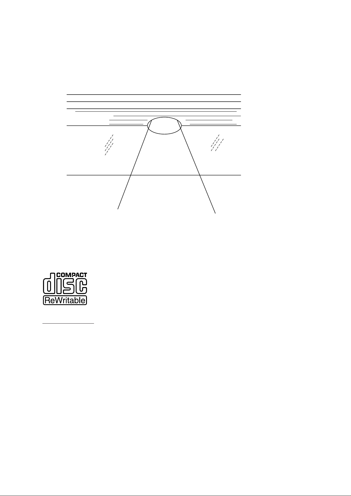
The organic dye coating, on its turn, is covered with a reflective layer. The coating is
initially transparent, and for recording it is heated by a laser beam.When the intensity of
the laser spot passes a certain threshold, a bump appears in the layer. This is an
irreversible process that drastically alters the optical characteristics.Using this technique,
a pit (or rather, bump) pattern is written in the tracking groove by a relatively high-power
laser in a dedicated recorder.The laser power required for recording is typically an order
higher than the 0.5mW laser power used for reading.
CD-ReWritab
le
CD-ReWritable may be seen as a logical extension of the CD-Recordable series of
systems, based on the same pre-grooved substrate as CD-Recordable with just another
type of recording layer.
CD-ReWritable drives will be able to write read and rewrite CD-ReWritable discs, as well
as writing and reading CD-Recordable discs and reading all CD-Audio discs.
With only a minor modification in electronics, which CD-Audio players will implement, all
future Philips CD-Audio players will be able to read CD-ReWritable discs.
protective coat
reflection layer
Recording layer
pit
PC substrate
laser
beam
PC substrate : >200 degrees C : expansion
Recording layer : 250 degrees C : melting
Philips Sound&Vision Service Department New Business LoB Disc Systems August 1997 Newsletter CDR97.01 3/10
Page 13

How CD-ReWritable recordings are made and erased
An erasable CD technology must, of necessity, be in har mony with the existing CD
systems. Philips persevered with phase change technology, by itself quite challenging in
compatibility terms. Phase, in this context, refers to the physical aggregation state of the
material used for the recording layer of the disc. There are two possible phases, with quite
different optical properties. A low-reflectance domain of amor phous, or patternless, phase
(equivalent to a CD pit) is produced when a laser heats the recording material raidly
above its melting point of 500-700ºC. Cooling very quickly, the amor phous domain
“freezes”. On the other hand, if the recording mater ial is heated to a rather lower
temperature for a somewhat longer time, a higher reflectance domain of polycrystalline
phase is formed, equivalent to a CD land.
Readout
Phase change tracks are read in the same way as regular CD tracks.The readout
mechanism does no more than detect the transitions between low and high reflectivity,
and measure the length of the periods between those transitions. Although the
reflectance is lower than the for regular CD’s, the relative proportions of light reflected
from the amorphous and polycr ystalline phases remains the same.
CD’s reflectance specifications are defined at 70% minimum for lands, 28% maximum for
pits. But with these specifications , the development of a recording material is a practically
impossible task; if 70% of the light is reflected, only 30% at most remains to change the
phase. Nowadays, these levels are not necessary: the photodiodes of today are able to
detect much lower reflectance differences. All that is needed is the correct reflectance
ratio and adequate amplification.That’s why the CD-format specifications have been
adapted accordingly.
The new CD-Recordable/ReWritable drives will write and re-write the CD-ReWritable
discs - as well as writing CD-Recordable discs. And future CD-drives, fitted with automatic
gain control, will be able to read them.
The recording material for CD-ReWritable consists of a layer of silver, indium, antimony
and tellurium.The polycrystalline phase reflects about 20% of the light, the amor phous
phase only 8%.That meets the requirement for a minimum modulation of 60%, and
allows for writing by a laser of 10-15mW.
CD-ReWritable thus conforms the original CD specification except in one small respect.
The discs have equal dimensions and store the same quantity of data.The drives
embody a small modification, but in other respects are identical.
Philips Sound&Vision Service Department New Business LoB Disc Systems August 1997 Newsletter CDR97.01 4/10
Page 14

3. The Discs
CD-DA:
• Playback of the audio CD’s. This disc is called Compact Disc Digital Audio (CD-DA).
CD-DA Recordable:
• Recording and playback of CD Digital Audio Recordable.
• This disc operates according to the Write Once principle. As long as disc is not finalised
music tracks can be added.(Depending to the max playtime of approx.74 min; 99
tracks can be inserted)
• Can be played on all CD-players after finalising the Recordable disc.
CD-ReWritable:
• Recording, Playback and Erasing on ReWritable Compact Discs
• After recording it is possible to erase the last track to correct recording mistakes
• After recording it is possible to erase the complete disc for re-use
• Can be played on CD-players prepared for ReWritable Discs after finalising
(current CD-players are not prepared)
Philips Sound&Vision Service Department New Business LoB Disc Systems August 1997 Newsletter CDR97.01 5/10
Page 15

4. CDR870 recording/playback functions
RECORDING FUNCTIONS
• Manual Recording
• Auto Start Recording (CD-Sync function)
• Pause Recording
• Manual Tracknumbering
• Automatic Tracknumbering
• Remaining recording time display
• Serial Copy Management System (SCMS)
• Erase last track (only CDRW disc)
• Erase disc (only CDRW disc)
PLAYBACK FUNCTIONS
• Play
• Pause
• Stop
• Direct track selection
• Next/Previous track selection
• Search forward/reverse
• Fast search
• Program play (20 tracks)
• Time display switching
TRACKNUMBERING DURING RECORDING
Automatic Digital Tracknumbering
• Automatic tracknumbering from CD/DAT/DCC/MD digital sources
Automatic Analogue tracknumbering
• When using the analogue input, tracknumbers are set automatically after detecting a
3 second pause in the music
Manual tracknumbering
• In manual track increment mode, tracknumbers can be set manually during recording
Important Notes:
Tracknumbering can not be changed after recording
Recording of indexes inside music tracks is not possible
Philips Sound&Vision Service Department New Business LoB Disc Systems August 1997 Newsletter CDR97.01 6/10
Page 16

5. Features
Auto-Start Recording (CD-SYNC)
• When using a known digital source (CD/DAT/DCC/MD) recording will star t automatically
when starting the digital source
• No special or separate connection with the source is needed for this besides the
coax/optical digital audio connection
CD-SYNC modes
• CD-SYNC: auto recording of all music tracks from the source
This mode is designed to make a copy of a complete disc or tape
• CD-SYNC1: automatic recording of 1 music track from the source
This mode is designed to make compilations by recording fully automatic
track-by-track
Sample Rate Conversion
• Digital sources with a sampling frequency other than the CD sampling rate of 44.1 kHz
are automatically converted.
• The Sample Rate Converter also removes all jitter from the digital input
Philips Sound&Vision Service Department New Business LoB Disc Systems August 1997 Newsletter CDR97.01 7/10
Page 17
6. Servicing
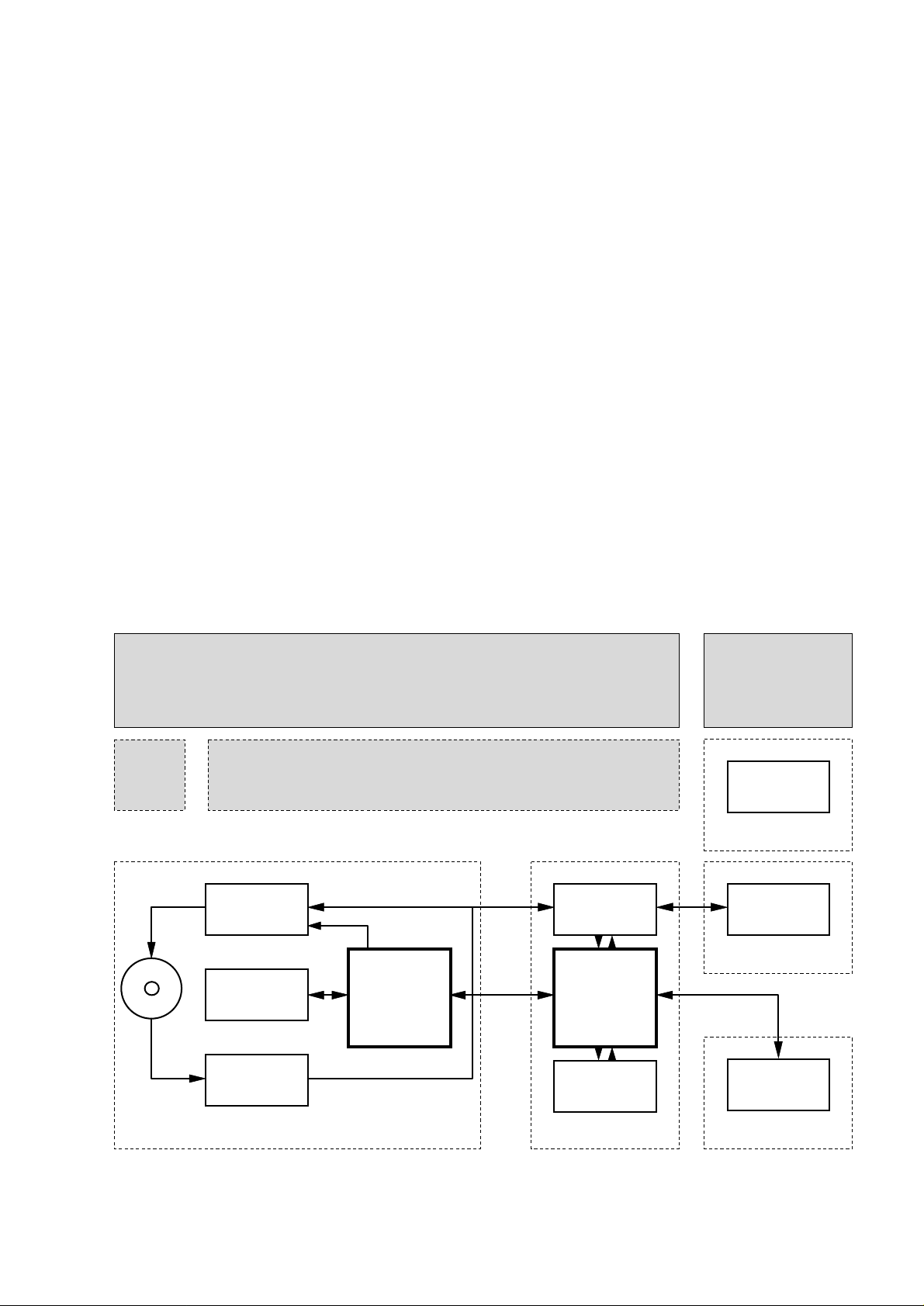
For servicing CDR870 this set can be divided into two parts.
1.The Power supply board, Display board and the Input/Output interface board has to be
repaired on component level.Detailed information will be available via Ser vice Manual
CDR870; 4822 725 25241.
2.The loader module with CD mechanism, CDM-board and the Main board will be
exchanged completely. For easy diagnostics this set is equipped with a selfdiagnose
program.To have repair costs lowered a repair procedure will be started and defective
loader modules have to be returned. Details will be given as soon as service
codenumber has been defined.
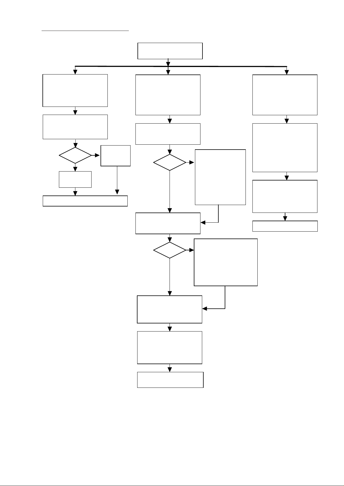
By means of the Service Test Program the playability of the set can be checked. See flow
chart on next page, ELECTRICAL SERVICE DIAGNOSTICS.
First of all do not forget to insert test disc SBC444A into the recorder, otherwise a fault
indication at disc test will be reported.
Then via actuating the PLAY NEXT and POWER ON keys simultaneously the Electrical
Service Diagnostics mode is star ted.
In case of an DERR or BERR fault indication the CDMLoader module has to be
exchanged.
We take it for granted that problems with power supply and display are solved before the
electrical service diagnostics has been started.
IIS
IIS
EFM
EFM
SPI
ENCODER
DATAPAD
ROM/RAM
SERVO
DECODER
BE-proc.
NEC
USER-proc.
HC11K4
DISPLAY
Basic engine User-part Display-part
I/O
I/O-part
POWER
SUPPLY
Supply-part
Main board
CDM-
part
Central repair CDMLoader Module
Local repair
on component
level
Philips Sound&Vision Service Department New Business LoB Disc Systems August 1997 Newsletter CDR97.01 8/10
Page 18
SERVICE TEST PROGRAM
MAIN BOARD TEST
Display shows blinking
“D -----”
Display shows blinking
during the test
“B -----”
during the test
BASIC ENGINE TEST
Display shows blinking:
“BUSY”
during the test.
DC ERASE
(erasement of complete disc)
Press
<ERASE> + <RECORD>
simultaneously and switch
power on
DISPLAY TEST
All segments are blinking at a
frequency of 1Hz.
To end test,
switch power off.
switch power off.
KEYBOARD/REMOTE TEST
Display shows name of
pressed key on keyboard or
remote control.
Display shows:
“
PASSED
”
when the erase function is
completed.
Display shows:
“
ER mm:ss
”
during the erase function.
mm
: remaining minutes
ss : remaining seconds
TOTAL
and
REM
are also
illuminated
ELECTRICAL SERVICE
DIAGNOSTICS
(advice for replacement units)
Press <PLAY> + <NEXT>
simultaneously and switch
power on
DEALER DIAGNOSTICS
(status of player)
Press <PLAY> + <STOP>
simultaneously and switch
power on
If power ON,
switch power OFF
Set OK?
to end test, switch power off
set displays:
“
PASSED
”
set displays:
“ERROR”
no
y
es
<NEXT>
<NEXT>
<NEXT>
Test OK?
set displays:
“BERR n”
n
=
1 : Communication bus error
2 : Basic Engine self test error
3 : Disc test error
no
y
es
Test OK?
set displays:
“DERR n”
n
=
1 : RAM test error
2 : ROM test error
3 : EEPROM test error
4 : DAIO test error
5 : GDIN test error
no
y
es
Insert test disc
SBC444A.
Philips Sound&Vision Service Department New Business LoB Disc Systems August 1997 Newsletter CDR97.01 9/10
Page 19
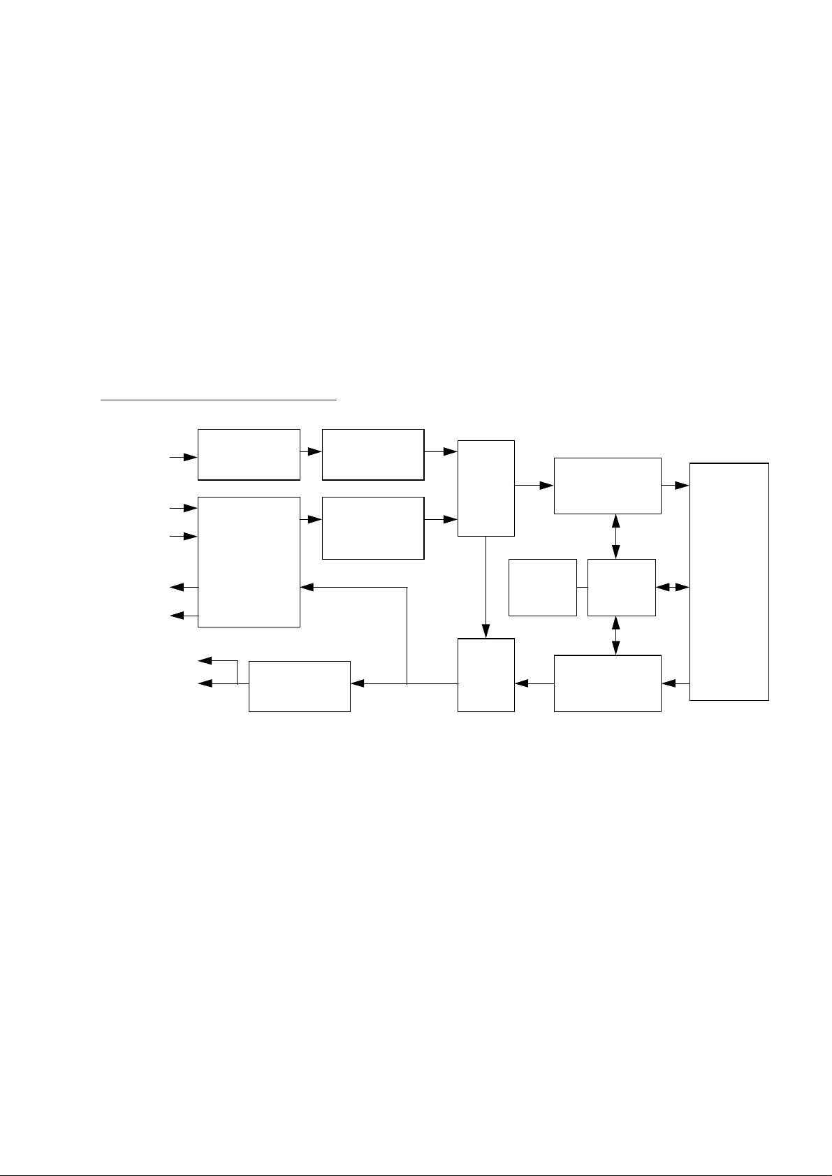
7. Block diagram of the CDR870
Finally we present the blockdiagram of CD-Recordable CDR870.
In Recording mode the analogue input has been converted into digital signal, which
signal can be monitored via the A/D switch, than the signal is encoded into EFM-format
and written onto the disc.The digital input sample rate may be converted before it is led
to the A/D switch.
In Playback mode the read EFM-signal is decoded and led to digital output stage and / or
converted into analogue audio signal in the DA Converter.
The µP is the heart of all these operations which controls the encoding and decoding
processes.
Block diagram of the CDR870
COMPACT
DISC
DECODER
CD60
MONITOR
SWITCH
D/A
CONVERTER
TDA1305
CDR
CDRW
DRIVE
OPTICAL
RECORDING
UNIT
CDM36
SAMPLE
RATE
CONVERTER
TDA1373
COMPACT
DISC
ENCODER
TDA1371
A/D
SWITCH
DIGITAL
INPUT
OUTPUT
INTERFACE
TDA1315
A/D
CONVERTER
SAA7366
RECORDING
LEVEL
CONTROL
ANALOGUE
INPUT
uP
CONTROL
DISPLAY
KEYS
IR REMOTE
HEADPHONES
ANALOGUE
OUTPUT
DIGITAL
OUTPUT
COAXIAL
OPTICAL
DIGITAL
INPUT
COAXIAL
OPTICAL
Philips Sound&Vision Service Department New Business LoB Disc Systems August 1997 Newsletter CDR97.01 10/10
Page 20

For internal use only PHILIPS
ISSUE AS97.03 (97-08-18)
Published by:
Service Depar tment Audio Systems
LINE OF BUSINESS AUDIO SYSTEMS
03.01 TYPENUMBER(S): AS445
SYMPTOM : The message “HELLO” is shown on the display.
CURE : This phenomenon only appears when the mains cable is connected
to the set, i.e. when moving the set to another place.
The message automatically disappears after a few seconds, when the
set switches into the standby-mode.
REMARKS :
03.02 TYPENUMBER(S): AS660C, AS665C, AS760C, AS765C, FW322C, FW332C, FW335C,
FW340C, FW342C, FW345C, FW352C, FW372C, FW362, FW363,
FW373C, FW382V, FW391C, FW392C, FW395C, M7C, M17C, M27C,
MC130, MC150, MC170, MX545
SYMPTOM : Var ious failures disappear when the set is opened or when
connectors are reconnected.
CAUSE : During production some JST connectors were changed from XH type
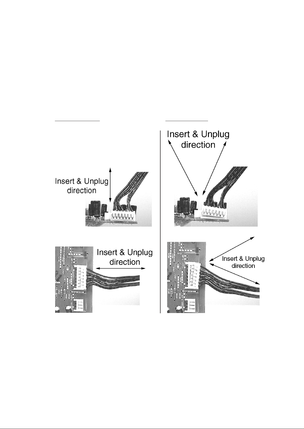
to EH type with smaller head.This new EH type is more fragile and
susceptable to deformation during plugging in and out of the
connector socket.When it is defor med it will result in poor or
intermittent contact.
CURE : 1. During repair ser vice technicians must handle the EH type
connectors with care.The correct way to plug it in and out is
indicated below.
2. All EH type connectors with an intermittent contact should be
replaced as a preventive action.
3. All the different wire assemblies had been standardized and are
available under the following service codes. For repair application
the wires should be cut to the correct length as required in the
defective set.
SERVICE NEWSLETTER
Service Newsletter 1997 – Audio Systems 1/8
Page 21
Order code Description
––––––––––––––––––––––––––––––––––––––––
4822 232 10395 6 pins Connector wire
4822 323 10396 5 pins Connector wire
4822 323 10405 4 + 3 pins Connector wire
4822 323 10397 4 + 5 pins Connector wire
4822 323 10398 6 + 4 pins Connector wire
4822 323 10399 4 + 4 pins Connector wire
REMARKS : This information is valid for sets produced from week 9646 onwards.
Improved material connectors are introduced in all sets by week
9712. New design plan to be introduced from May 1997 onwards.
Correct handling
Wrong handling
Service Newsletter 1997 – Audio Systems 2/8
Page 22

03.03 TYPENUMBER(S): AS760C, AS765C
SYMPTOM : Volume drops after some time due to clipping circuit.
CURE : The output drop is due to an obsolete NTC & clipping circuit.
The problem can be fixed by deleting resistor 3472.
REMARKS : This problem may occur in sets with production code RZ..., produced
before week 9704.
03.04 TYPENUMBER(S): FB560
INFORMATION : For above mentioned loudspeaker system no Service Manual has
been published.The FB560 loudspeaker system consists of the
loudspeaker boxes
• FB561 (front)
• FB562 (center)
• FB563 (surround)
The following spare parts are available:
Service Code Article Description Impedance Application
–––––––––––––––––––––––––––––––––––––––––––––––––––––––
4822 240 10085 Woofer 5 1/4” 12Ω FB561
4822 240 10088 Tweeter 8Ω FB561
4822 240 10086 Woofer 4” 12Ω FB562
4822 240 10088 Tweeter 8Ω FB562
4822 240 10087 Full range 5 1/4” 6Ω FB563
REMARKS :
03.05 TYPENUMBER(S): FW332
SYMPTOM : POP Button does not function.
CURE : The problem is caused by the POP button activating point, which
does not land correctly onto tact switch 1413.
This can be solved by:
• Remounting the switch 1413 or
• Shortening the stopper pins around the switch area by 0.5mm
CA
UTION: Do not overdo this cutting because it may lead to easy
breakage of the button hinge point when the customer
over-presses the button.
REMARKS :
Service Newsletter 1997 – Audio Systems 3/8
Page 23
03.06 TYPENUMBER(S): FW332, FW335, FW362, FW363
SYMPTOM : The drawer gear wheel 202 and CAM wheel 204 are out of position.
CURE : The fault is due to an obsolete CAM gear wheel which is white in
colour.Replace this part with the improved gear wheel (pos. 204)
which is grey in colour.
REMARKS : Improved CAM gear wheel was introduced in production from week
9704 onwards.
03.07 TYPENUMBER(S): FW332, FW335, FW352C, FW355C, FW362, FW363, FW372C,
FW373C, FW375P, FW382V, FW395C, FW630, FW650C, FW670P,
FW680V, FW725C, FW730C, FW745C, FW750C, FW780P, FW790P,
M7C, M17C, M27C, M37DC, MC130, MC150, MC170, MC172
SYMPTOM : No sound when the set is switched from LW to STANDBY and
afterwards switched-on again in LW-mode.
CURE : The fault is caused by IC 7101 TEA5762 (4822 209 90315).
The problem can be fixed as follows:
• Replace IC 7101 TEA5762 (4822 209 90315) or
• Add 1pF chip capacitor (4822 122 32447) across resonator 5121 or
• Change chip resistor 3162 from 150kΩ to 270kΩ (4822 051 20274)
REMARKS : This problem may be present in all sets using Tuner 95 board
produced before 6th March 1997 (week 9710).
03.08 TYPENUMBER(S): FW362, FW363, FW372C, FW373C, FW382V, FW383V, FW395C,
FW710C, FW725C, FW730C, FW745C, FW750C, FW770P, FW780P,
FW790P, M7C, M17C, M18C, M27C, M28C, M37DC, M38C, M48DC,
MX545, MX555
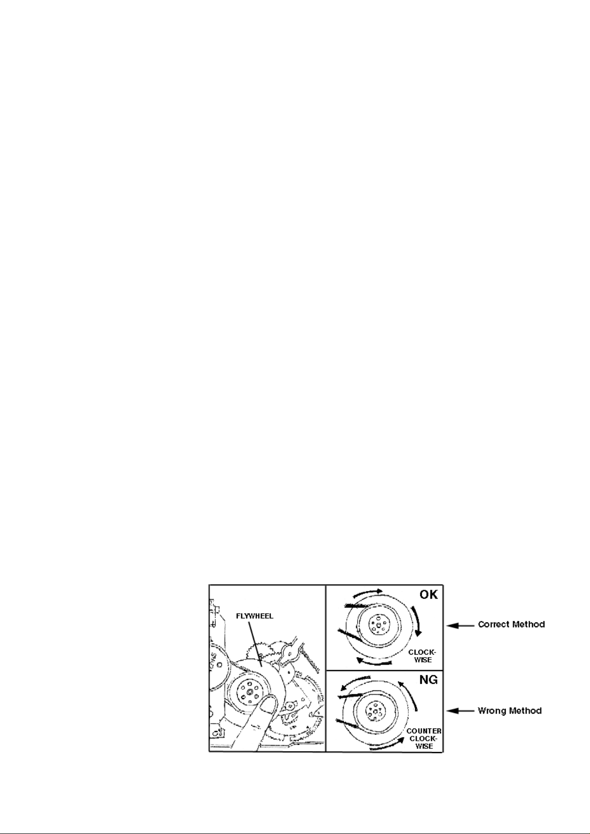
INFORMATION : Repair hint,Tape Mechanism
During repair or when the Tape mechanism needs to be reset for any
reason, the flywheel can be turned manually. This can be done by
turning the flywheel slowly in the clockwise direction. Counter
clockwise motion must not be done because it may dent or damage
some of the gears in the mechanism. See picture below.
REMARKS :
Service Newsletter 1997 – Audio Systems 4/8
Page 24

03.09 TYPENUMBER(S): FW372C/22B
SYMPTOM : The RDS function does not work.
CURE : The problem is because of 3 missing parts on the Front Board.
The solution is to add:
• Resistors 3542 and 3545 (both 10kΩ, 4822 116 83864)
• Coil 5407 (2,2µH, 4822 156 21721)
REMARKS : This problem may be found in sets star ting with ser ial number
CB01 9714 0.....
03.10 TYPENUMBER(S): FW395, MC170
SYMPTOM : The tape mechanism fails and cassette cannot be taken away.
CURE : The cause is due to Cam gear shaft cracked by weld line.
Replacement of control disc (pos. 25 in MC170) is not recommended
because of critical assembly & alignment control.
For such problem the complete deck should be replaced.
REMARKS : Improved tape mechanism can be recognized by label on the tape
mechanism’s motor. The label should read:
FW395C MC170
–––––––––––––––––––––––––––––––––––––––––––––––––––
CWB44FR03 ......H onwards 60718xxM/C onwards
(eg. CWB44FR03 6102805AH) (year 96, July, 18 onwards)
Service Newsletter 1997 – Audio Systems 5/8
Page 25
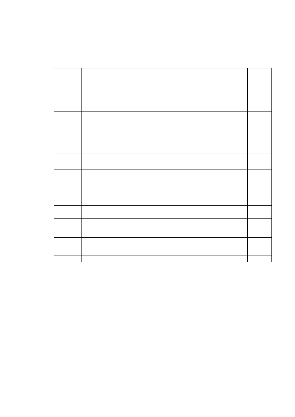
03.11 TYPENUMBER(S): FW620C, FW650C, FW670P, FW672P, FW680V
INFORMATION : Correction Service Manual, Ser vice Test Program
The table of error codes, published in the Service Manual chapter
“Service Test Program”, is not correct.
The error numbers and descriptions should read as follows:
REMARKS :
Error number Error typeError description
1002 Focus Error.
Triggered when the focus could not be found within a certain time when starting up
the CD or when the focus is lost for a certain time during playing the CD.
1007 Subcode Error.
No subcode could have been read, even not after retrying 10 times to restart the PLL
and jumping 10 tracks. When this happens the servo is stopped and restarted (as if
the user would have pressed stop and then play immediately) to recover.
1008 Out of lead-in during reading TOC
Triggered when during reading the TOC the lead-in (track no. 0) is left.
This can be caused by a misaligned inner-switch or by a disc with a mispositioned lead-in.
1010 Radial error
Triggered when the radial servo is not on track for a certain time during playing the CD.
1011 Sledge error
Generated when the inner-switch did not open within a certain time when the pick up is
moved from the inner position outside.
1012 Fatal sledge error
Generated when the inner-switch did not close within a certain time when the pick up is
moved inside. Inner-switch or sledge motor problems.
1013 Turntable motor error.
Generated when the CD did not reach 75% of speed during startup within a certain time.
Discmotor problem.
1020
F
W
W
F
W
F
F
WPLL lock error.
When the PLL did not lock after 10 retries then this warning message is generated and
the servo is stopped and restarted (as if the user would have pressed stop and then
play immediately) to recover.
1070 FCarriage did not reach the play position within a certain time.
1071 FCarriage did not reach the stocker within a certain time.
1072 FCarriage did not pass the play position within a certain time.
1076
1)
WTray open position not reached within a certain time.
1077
1)
1)
corrected value
FMiscounting of the stocker position occured
1073
1)
WDesired disc position of the stocker could not be reached within a certain time.
1074
1)
FGenerated when the cam is moved and either SW1 or SW2 did not open within a certain time.
1075
1)
FGenerated when the cam is moved and either SW1 or SW2 did not close (reach the new
position) within a certain time.
Service Newsletter 1997 – Audio Systems 6/8
Page 26
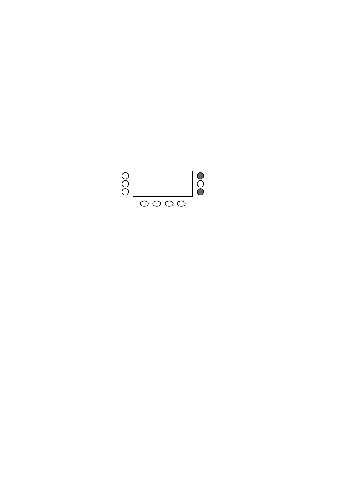
03.12 TYPENUMBER(S): FW670P
SYMPTOM : If the custormer changes the mode or any volume/DSC setting on the
set, the new setting will be automatically stored in the EEPROM.
If now the set is switched off after 1 second of the last setting change
on the set, it is possible that a wrong information will be written to the
EEPROM. If the set is switched on, the customer can have a strange
volume knob function.
The volume setting is at mininum but the output power is very
loud.
CURE : The solution is to clear the EEPROM.
Step 1 : Hold down button B1 & B3 (see fig.1) while
plugging in the mains.
Step 2 : Press Center
Step 3 : Disconnect mains
The EEPROM will load with default data.Please note that the
customer settings like Tuner settings will be lost.
fig.1
REMARKS : The EEPROM clear procedure can also be found in the FW670P
service manual page 3-9.
03.13 TYPENUMBER(S): MC130
SYMPTOM : The clock is inaccurate and runs 20 seconds too slow per day.
CURE : The cause of the problem is due to the Quartz frequency out of
specification.This problem is solved by changing capacitors 2404 and
2405 from 120pF to 15pF (5322 122 33869).
REMARKS :
03.14 TYPENUMBER(S): MX732
SYMPTOM : Some sets are delivered with wrong AM grid 10kHz instead of 9kHz.
CURE : The sets can be adapted by the local service workshop by the
procedure given below:
1. Remove jumper J284 (on the Front board)
2. Add jumper J283
REMARKS :
DISPLAY
B1
B3
Service Newsletter 1997 – Audio Systems 7/8
Page 27

03.15 TYPENUMBER(S): MX960PRO, MX960AHT
SYMPTOM : The set does not work and the display shows
“CHECK OWNER’S MANUAL”.
CURE : The connector CN808 on the CD decoder board is not properly
connected. Fix the connector properly.
REMARKS :
Service Newsletter 1997 – Audio Systems 8/8
Page 28

For internal use only PHILIPS
ISSUE PA97.04 (97-07-31)
Published by:
Service Depar tment LOBPA Hong Kong
LINE OF BUSINESS PORTABLE AUDIO
04.01 TYPENUMBER(S): AZ1202, AZ1302, AZ1307, AZ1308, AZ1407, AZ1508, AZ1509,
AZ1602, AZ2100, AZ2600, AZ2605, AZ2615, AZ2804, AZ2805,
AZ2808, AZ8050, AZ8051, AZ8052, AZ8055, AZ8056, AZ8057,
AZ8061, AZ8068, AZ8070, AZ8075
INFORMATION : The Pinch Roller Arm Assembly (items 10 + 11 + 12) on the cassette
mechanism is now available under service code 4822 528 11189.
REMARKS :
04.02 TYPENUMBER(S): AZ2100, AZ2600
INFORMATION : From July 1997 onwards, with factory code star ting from KT02
9729..., new CDM and CD6 boards are used.
For servicing please refer to:
Service Information A97-576 (4822 725 25628) for AZ2100 and
Service Information A97-577 (4822 725 25629) for AZ2600.
REMARKS :
04.03 TYPENUMBER(S): AZ7360, AZ7362, AZ7363, AZ7364, AZ7365, AZ7366, AZ7368,
AZ7372, AZ7376, AZ7453, AZ7457, AZ7460, AZ7462, AZ7463,
AZ7464, AZ7465, AZ7474, AZ7476
SYMPTOM : Laser light-pen is dead.
CURE : The light-pen is probably damaged by the high electromagnetic
radiation especially from mobile phone transmission.
The CDM has to be replaced.
To avoid this fault to be happened again, change 2902 from 10nF to
1nF (5322 122 34123).
REMARKS : Modification had been implemented in production from week 9716
onwards.
SERVICE NEWSLETTER
Service Newsletter 1997 – Portable Audio 1/2
Page 29

04.04 TYPENUMBER(S): AZ7453, AZ7457, AZ7460, AZ7462, AZ7463, AZ7464, AZ7465,
AZ7474, AZ7476
SYMPTOM : “Pop” noise is audible when ESA/ESP is on.
CURE : The working voltage of DRAM 7851 is low.
Solution 1: Change resistor 3852 from 22Ω to 0Ω jumper
(4822 051 20008).
Solution 2: Replace 7851 (4822 209 12993).
REMARKS : 3852 had been changed to 0Ω in production from week 9730
onwards.
04.05 TYPENUMBER(S): AZ7562, AZ7565, AZ7566
SYMPTOM : “Pop” noise is audible when ESA/ESP is on.
CURE : The working voltage of DRAM 7851 and 7852 is low.
Solution 1: Change resistors 3852 and 3853 from 22Ω to 0Ω jumper
(4822 051 20008).
Solution 2: Replace 7851 and 7852 (4822 209 12993).
REMARKS : 3852 and 3853 had been changed to 0Ω in production from week
9730 onwards.
Service Newsletter 1997 – Portable Audio 2/2
Page 30

For internal use only PHILIPS
ISSUE PA97.03 (97-06-30)
Published by:
Service Depar tment LOBPA Hong Kong
LINE OF BUSINESS PORTABLE AUDIO
03.01 TYPENUMBER(S): AE2340
SYMPTOM : Display is dim or no segments are visible.
CURE : Capacitors C1 (22nF) and C4 (100nF) are defective and have to be
replaced.
REMARKS : Improved capacitors are used in production from week 9724 onwards.
03.02 TYPENUMBER(S): AQ6463
SYMPTOM : The fast WIND and/or REWIND button stuck.
CURE : The spring near the common wheel is loose because the spring
holder has broken by extreme large force applied to the button.
Because both buttons are rather small and rather close to each other,
the undesired button can accidentally be pressed down together with
the other button.
REMARKS : No corrective actions can be taken due to the product design.
Design of successors will be improved.
03.03 TYPENUMBER(S): AW7150, AW7160, AW7250
INFORMATION : The Recording Lever (pos. 503) is now available via ser vice
codenumber 4822 402 10786.
REMARKS :
SERVICE NEWSLETTER
Service Newsletter 1997 – Portable Audio 1/3
Page 31

03.04 TYPENUMBER(S): AZ1302, AZ1307, AZ1308, AZ1407, AZ1508, AZ1509, AZ2804,
AZ2805, AZ2808
SYMPTOM : The Gear Wheels (pos.202 and 204) are out of position.
CURE : The problem occurs when the Drawer (pos. 216) gets stuck and the
customer pushes it back strongly by hand.It is recommended to
replace not only the 2 Gear Wheels but also the Drawer.
REMARKS : The tooling of the Drawer (4822 444 40727) has been modified.
New Drawers are implemented in production from week 9648
onwards.
03.05 TYPENUMBER(S): AZ2100
INFORMATION : Correction Service Manual, Electrical par tslist:
For version /00 and /05, the service codenumber of the Mains
transformer should read 4822 146 10768.
REMARKS :
03.06 TYPENUMBER(S): AZ2405
SYMPTOM : Preset tuner frequencies get lost when the mains is disconnected.
CURE : To extend the memory retaining time Zener diode ZD302 must be
changed from 4.7V to 6.8V (4822 130 34278).
REMARKS : It is advised to change ZD302 in every set, brought in for repair.
Modification will be implemented in production from week 9730
onwards.
03.07 TYPENUMBER(S): AZ2405
INFORMATION : Correction Service Manual, Electrical par tslist:
The service codenumber of IC101 TA2065F should read
4822 209 15462.
REMARKS :
03.08 TYPENUMBER(S): AZ7260, AZ7261, AZ7262, AZ7265, AZ7266, AZ7267, AZ7268,
AZ7271, AZ7272, AZ7275, AZ7278
INFORMATION : For sets with factory change code KT02, some statements in the
Instruction for Use are found to be wrong.
On the page of CONTROLS, the STOP button will not activate
charging.The fact is that the NiCad battery pack will be charged
automatically if the mains adaptor is connected.
Also in the TROUBLESHOOTING chapter, words “no CHARGE
indicator” should be deleted because “CHARGE” will never appear on
the display.
REMARKS : Instruction for Use will be updated from week 9731 onwards.
Service Newsletter 1997 – Portable Audio 2/3
Page 32

03.09 TYPENUMBER(S): AZ8050, AZ8051, AZ8052
INFORMATION : For COMBI board “A03” (used in sets produced until October 1995),
the microprocessor IC 7800 is replaced by an OTP version.
When ordering the original codenumber 4822 209 90147, the OTP
version 4822 900 11116 will be delivered automatically.
REMARKS :
03.10 TYPENUMBER(S): AZ8050/..D, AZ8051/..D, AZ8052/..D, AZ8061/..D, AZ8070
SYMPTOM : CD does not work because the disc drive is tilted.
One of the disc drive holders (pos. 440) is out of position.
CURE : The fault is caused by heavy shocks.
The problem can be solved by remounting the holder.
It is recommended to add a metal plain washer (outer diameter 9mm)
on the top of the holder.In this case the length of the screw must be
changed from 8mm to 10mm.
REMARKS : This information is only valid for versions using the CD93 disc drive.
Improved mounting process has been implemented in production
from week 9710 onwards, washer has been added from week 9724
onwards.
03.11 TYPENUMBER(S): ST2010, ST4010, TK6010,TS2100
INFORMATION : The laser pick-up (4822 691 20795) is not available.
We suggest to replace the complete CD mechanism, service
codenumber 4822 691 30342.
REMARKS :
Service Newsletter 1997 – Portable Audio 3/3
Page 33

For internal use only PHILIPS
ISSUE PA97.02 (97-05-31)
Published by:
Service Depar tment BUPA Hong Kong
LINE OF BUSINESS PORTABLE AUDIO
02.01 TYPENUMBER(S): AE2045, AE2140, AE2145
INFORMATION : From week 9715 onwards, the design is changed.
A new rotatable telescopic aerial is used.The two different aer ials are
not inter-changeable.
4822 303 14018 Aerial (not rotatable)
4822 303 14057 Aerial (rotatable)
REMARKS :
02.02 TYPENUMBER(S): AJ3840
INFORMATION : If the Clock IC is TMS3459BNL and spare part is not available, it is
suggested to be replaced by LM8562B (4822 209 32851) and change
the value of the following parts:
R122 (pin 16 to ground) changed to 180kΩ
C109 (pin 15 to pin 16) changed to 0.0033µF
REMARKS :
02.03 TYPENUMBER(S): AQ6546
SYMPTOM : Auto reverse cassette deck plays at one direction only.
CURE : The reverse mechanism is interrupted by C70 (1µF/50V) which can
be replaced by a SMD capacitor (4822 126 11692).
REMARKS : SMD capacitor was used in production from week 9708 onwards.
02.04 TYPENUMBER(S): AQ6546
SYMPTOM : Battery inser ting is difficult.
CURE : The batteries are blocked by the flat cables connecting to the
equalizer board on the cassette door.
A piece of PVC adhesive tape (35mm x 3.8mm) can be used to cover
the flat cable that extended under the battery cavity.
REMARKS : Modification was implemented in production from week 9708
onwards.
SERVICE NEWSLETTER
Service Newsletter 1997 – Portable Audio 1/3
Page 34

02.05 TYPENUMBER(S): AW7550
INFORMATION : Correction Service Manual, Electrical par tslist:
For AW7550/14, the ser vicecode of the band switch S1 should read
4822 277 11626.
REMARKS :
02.06 TYPENUMBER(S): AZ1100, AZ1101, AZ1102
INFORMATION : Correction Service Manual, Electrical par tslist:
The tuning capacitor is missing. It is available via service code
4822 125 11097.
REMARKS :
02.07 TYPENUMBER(S): AZ1100, AZ1101, AZ1102
INFORMATION : Correction Service Manual,Tape deck:
The type number of motor should be EG-530YD-9BH which is
available via service code 4822 361 21592.
REMARKS :
02.08 TYPENUMBER(S): AZ1100, AZ1101, AZ1102
SYMPTOM : A strange fragrance is smelt from the set.
CURE : When a set is connected to the mains, the mains-transformer
becomes warm and produces a strong fragrance.
There are no technical failures found in the set.The transformer
supplier confirmed bad smell is come from the varnish after heat.
It is normal and no Hazard for Health.
REMARKS :
02.09 TYPENUMBER(S): AZ1602
INFORMATION : Correction Service Manual, Electrical par tslist:
On CD97 board, service code of 2829 should read 4822 124 23178.
REMARKS :
02.10 TYPENUMBER(S): AZ2100, AZ2600, AZ2605
SYMPTOM : Hum noise from mains-transformer is audible.
CURE : The varnish of the transformer is not sufficient.
Transformer 4822 146 10396 has to be replaced.
REMARKS : Vacuum varnish process is applied in transformer manufacturer from
week 9713 onwards.
Service Newsletter 1997 – Portable Audio 2/3
Page 35

02.11 TYPENUMBER(S): AZ2100, AZ2600, AZ2605
SYMPTOM : The tuning pointer does not move.
CURE : The pole on the tuner bracket for holding the pulley is broken.
The Tuning bracket has to be replaced.The Bracket is now available
via service code 4822 464 10291.
REMARKS :
02.12 TYPENUMBER(S): AZ2405
INFORMATION : During production, LD202 and LD203 (to light up volume controls)
were changed from orange to green.
Service code of green LED is 4822 130 10668.
REMARKS :
02.13 TYPENUMBER(S): AZ8340,AZ8345,AZ8440,AZ8445,AZ8540
INFORMATION : From June of 1995 onwards, the front cabinet was modified by adding
4 round poles so that the cassette buttons can be mounted on the
front cabinet instead of mounted on the tape deck.
The new Cabinet-Front Assembly is available via service code
4822 459 04552.
REMARKS :
02.14 TYPENUMBER(S): AZ8350, AZ8351, AZ8352
INFORMATION : Correction Service Manual, Mechanical par tslist:
Item 419 is 4822 410 63178 Power/Mode Knob
Item 423 is not used in this model.
REMARKS :
02.15 TYPENUMBER(S): AZ8357
INFORMATION : Correction Service Manual, Mechanical par tslist:
Item 419 is 4822 410 63178 Power/Mode Knob
Item 423 is 4822 411 61975 Spatial Knob
REMARKS :
03.16 TYPENUMBER(S): AZ8567
INFORMATION : Correction Service Manual, Mechanical par tslist:
The service codenumber of item 401 Front Cover should read
4822 423 51202.
REMARKS :
Service Newsletter 1997 – Portable Audio 3/3
Page 36

For internal use only PHILIPS
ISSUE AS97.02 (97-03-31)
Published by:
Service Depar tment Audio Systems
LINE OF BUSINESS AUDIO SYSTEMS
02.01 TYPENUMBER(S): Compact Disc drives CDM12.1/15, CDM12.3BLC
INFORMATION : Additional information to Newsletter issue 96.09.01 concerning
objective lens cleaning.
A cleaning solvent B4-No2 can be ordered with service codenumber
4822 389 10024 and may only be used for plastic lenses as
described in Newsletter issue 95.58.01.
REMARKS :
02.02 TYPENUMBER(S): AZ3705, AZ3708, FW14, FW15, FW36, FW56, FW350C, FW351C,
FW360C, FW370G, FW620C, FW650C, FW670P, FW680V, 74MX540
INFORMATION : CD changer module
During production the spring pos. 70 has been modified from 16mm
length to 14mm in order to match a similar change on bracket pos. 2.
This makes matching between the bracket and spring necessary
during repair. For this reason an additional service codenumber for
the new spring was created:
Service code Description
––––––––––––––––––––––––––––
4822 492 42713 Spring 16mm
4822 492 11413 Spring 14mm
REMARKS :
02.03 TYPENUMBER(S): CDC745
SYMPTOM : In shuffle mode with 5 discs, some tracks are never played and some
others are played several times.
CURE : The problem is caused by the software of the set.As the production
has already been stopped there is no solution available.
REMARKS :
SERVICE NEWSLETTER
Service Newsletter 1997 – Audio Systems 1/6
Page 37

02.04 TYPENUMBER(S): FW17, FW18
INFORMATION : Service Manual, Partslist
The ordering code for the complete tape mechanism CRF4119 R/P is
4822 691 20954.
REMARKS :
02.05 TYPENUMBER(S): FW17, FW18, FW40, FW41, FW46, FW56
INFORMATION : The slow (damping) eject of cassette door is caused by the grease
between the gear damper and gear holder.When replacing any of
these 2 parts it is necessar y to refill the grease content.
The grease G-331 is now available under 4822 390 10149.
The 2 parts can be identified by the position numbers in the exploded
view of the tape mechanism:
Gear damper Gear holder Model used
–––––––––––––––––––––––––––––––––––––––––––––––
pos. 10 pos. 9 FW17, FW18
pos. 14 pos. 13 FW40, FW41, FW46, FW56
REMARKS :
02.06 TYPENUMBER(S): FW330
INFORMATION : Service Manual, Partslist
On customer request the 25P female socket (pos. 1401) on the Front
board is now available under 4822 267 60418.
REMARKS :
02.07 TYPENUMBER(S): FW332
SYMPTOM : The tray of the CD player opens until approximately 2cm before the
end position and closes again immediately.
Lever pos. 214 touches jumper 9823.
CURE : Remove jumper 9823 from the component side and resolder it on the
copperside of the printed board.
REMARKS :
02.08 TYPENUMBER(S): FW332
INFORMATION : Service Manual, Mechanical par tslist
The lever from tape deck to record switch pos. 1707 is now available
under service codenumber 4822 402 10126.
REMARKS :
Service Newsletter 1997 – Audio Systems 2/6
Page 38
02.09 TYPENUMBER(S): FW362
INFORMATION : Service Manual, Mechanical par tslist
The service codenumber for Cabinet rear pos. 298 should read
4822 426 10187 for all versions. 4822 426 10069 is cancelled.
REMARKS :
02.10 TYPENUMBER(S): FW362, FW372C
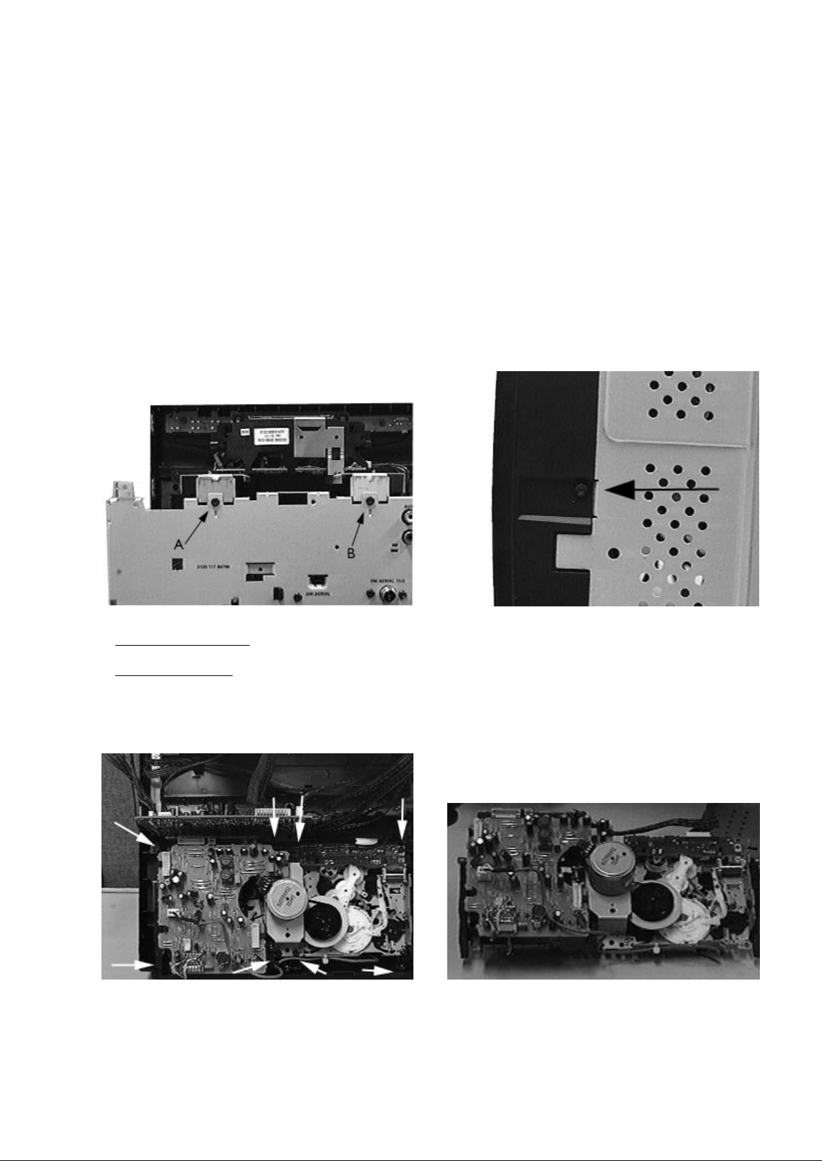
INFORMATION : Adjustment of tape speed
In order to get access to the potmeters for tape speed adjustment the
complete tape module must be dismantled (see instructions below).
REMARKS :
First remove the top cabinet of the set.
CD Shortloader Module:
Loosen the 2 screws indicated in the picture above.
CD Changer Module:
Loosen the 2 screws at the back panel & the 2 screws
on the front tray of the CDC module.
Remove the CD module.
1)
2)
3)
Turn the set aside and loosen the bottom screw as
indicated in the picture above.
Detach the front panel from the bottom panel.
4)
5)
The tape module is now in a proper position for
servicing and troubleshooting.
9)Loosen the 8 screws of the tape module as indicated
in the picture above
(Note: 4 short screws on top, 4 long screws below).
Release all wires of the tape module.
Slowly detach the tape module from the cassette door.
6)
7)
8)
Service Newsletter 1997 – Audio Systems 3/6
Page 39

02.11 TYPENUMBER(S): FW395C
INFORMATION : Service Manual, Electrical par tslist - Front Board
The correct service codenumber for the Microprocessor should be
4822 209 13144 TMP87CS71F with marking “372S51141”.
REMARKS :
02.12 TYPENUMBER(S): FW730C
INFORMATION : Service Manual, Electrical par tslist - Front Board
In the parts list of the Front board the Microprocessor IC 7441 is not
clear indicated.The service codenumbers are:
4822 209 15475 TMP87CS71AF marking “770S51491”
for versions /21/21M/34
4822 209 15476 TMP87CS71AF marking “770S51501”
for versions /22/22S/25
REMARKS :
02.13 TYPENUMBER(S): FW770P
INFORMATION : For practical cost saving the following items have been
changed/deleted:
1.Screw pos.308 (2x) is deleted
2.Transformer bracket pos. 200 is deleted
3.Insulation plate pos. 290 is deleted
4.Screw pos.296 is reduced to 1pc for the centre position only
5.Screw pos.313 is reduced by 2pcs - rear cabinet mounting point
at the bottom-most left and right positions are deleted.
REMARKS : Implemented from production week 9701 onwards.
02.14 TYPENUMBER(S): FW770P
INFORMATION : Service Manual, Mechanical par tslist - Main unit
On commercial request the Philips badge pos. 243 is changed from
4822 459 11086 to 4822 459 11055.
REMARKS : Implemented from production week 9701 onwards.
Service Newsletter 1997 – Audio Systems 4/6
Page 40

02.15 TYPENUMBER(S): FW770P
INFORMATION : Changes in course of production:
AF3 Board (Effective from production week 9648 onwards)
1.Resistors 3561/3562 are changed to 2.2kΩ 1% 0.1W
(4822 117 11449)
Reason: For noise reduction.
2.Resistors 3631/3632 are changed to 560Ω 5% 0.5W
(4822 116 52226)
Reason: For reducing the distortion at high volume.
F
ront Board (Effective from production week 9648 onwards)
1.Resistor 3516 is changed to 15kΩ 5% 0.1W
(4822 051 20153)
Resistor 3649 is changed to 2.2Ω 5% 0.1W
(4822 051 20228)
Reason: Increase of sensitivity of VU-meter and prevent
false indication.
2.Delete diode 6422
Reason: Error in par ts list
ETF2 Board (Effective from production week 9650 onwards)
1.Capacitor 2784 is changed to 15nF 10% 50V (4822 121 51305)
Resistor 3769 is changed to 10kΩ 1% 0.1W (4822 117 10833)
Resistor 3772 is changed to 6.8kΩ 5% 0.1W (4822 051 20682)
Resistor 3775 is changed to 4.7Ω 5% 0.1W (4822 051 20478)
Resistor 3778 is changed to 6.8Ω 5% 0.33W (4822 052 10688)
Reason: Increase of erase current to solve marginal erase
damping.
REMARKS :
02.16 TYPENUMBER(S): FW780P/21S
INFORMATION : Service Manual, Partslist
Correction of service codenumbers in Exploded view of set and
Loudspeaker drawings:
Chapter Pos no. Service code Description
––––––––––––––––––––––––––––––––––––––––––––––––––––
14-2 241 4822 450 10228 Window Cassette Left
14-2 242 4822 450 10229 Window Cassette Right
15-1 3 4822 459 04544 Front Panel Assy Silver
15-1 - 4822 124 11982 3.3µF 50V Non-polarity
REMARKS :
02.17 TYPENUMBER(S): MC170
INFORMATION : Service Manual, Speakerbox
The service code for the tweeter should read 4822 240 70274 instead
of 4822 247 70274.
REMARKS :
Service Newsletter 1997 – Audio Systems 5/6
Page 41

02.18 TYPENUMBER(S): MC170
SYMPTOM : During high sound reproduction level, the Loudspeaker boxes move
when placed on a smooth surface due to vibration.
CURE : This problem can be solved by adding 4 pieces of r ubber foot to keep
it in position.
The service code for rubber foot is 4822 462 40683.
REMARKS :
02.19 TYPENUMBER(S): MX731
INFORMATION : In the MX731 system package the label on the Loudspeaker box is
LSB680V21HT instead of FB680V/21 as indicated in the Service
Manual.This loudspeaker box is correct and to avoid confusion it will
be changed to FB680V/21 for set production from April 1997
onwards.
REMARKS :
Service Newsletter 1997 – Audio Systems 6/6
Page 42

For internal use only PHILIPS
ISSUE 97.01 (97-01-31)
Published by:
Service Depar tment Audio Systems
01.01 TYPENUMBER(S): AQ6524
INFORMATION : During production, two types of headphone sockets were used.
Because body dimension and the pins location of the sockets are
different, correct parts must be ordered.
1. 4822 267 31595 : body is rectangular (5 x 7 mm)
2. 4822 267 31861 : body is square (6 x 6 mm)
REMARKS :
01.02 TYPENUMBER(S): AW7560
INFORMATION : Information of Service newsletter 96.09.02 is wrong.
The type number of the motor is M9T90U20-T.
Service code should read 4822 361 10958.
REMARKS :
01.03 TYPENUMBER(S): AZ1100, AZ1101, AZ1102
SYMPTOM : The mains transformer is defective.
CURE : The capacitors C801, C802, C803 and C804 which are connected in
parallel with rectifier diodes will burn out and short circuit by high PP
transit voltage.This causes damage of the mains transformer.
Capacitors must be replaced with ceramic capacitors of 0.022µF/63V
(e.g. 4822 122 30103).
REMARKS : Capacitors with higher voltage rating are used in production from
week 9633 onwards.
When sets produced before week 9633 or the 4 capacitors are
marked with “AEC” are brought in for repair, we suggest to replace
the capacitors with 4822 122 30103 or capacitors with equivalent
specification.
SERVICE NEWSLETTER
Service Newsletter 1997 – Audio Systems 1/8
Page 43

01.04 TYPENUMBER(S): AZ1100, AZ1101, AZ1102
INFORMATION : Service Manual, par tslist
The mains cord set for /17 versions is available with service code
4822 321 10862.
REMARKS :
01.05 TYPENUMBER(S): AZ1307, AZ1308, AZ1407, AZ1508, AZ2805, AZ2808, AZ8050,
AZ8051, AZ8052, AZ8055, AZ8056, AZ8057, AZ8061, AZ8068,
AZ8070, AZ8075, AZ8150, AZ8262, AZ8267, AZ8297
INFORMATION : Service Manual, Mechanical par tslist
Correct Service code number for “mains socket IEC” reads
4822 265 20318.
REMARKS :
01.06 TYPENUMBER(S): AZ2405
INFORMATION : The service code of IC101 TA2065F should read 4822 209 15462.
The Remote Transmitter Assy is now available with service code
4822 219 10196.
REMARKS :
01.07 TYPENUMBER(S): AZ3705, AZ3708, FW14, FW15, FW36, FW56, FW350C, FW351C,
FW360C, FW370G, M25, M26, MX520
INFORMATION : Pos 48 for the CDC mechanism is now available as service spare
part. The 12NC is 4822 401 11681 Chassis clamper.
REMARKS :
01.08 TYPENUMBER(S): AZ6834, AZ6835, AZ6836, AZ6837
SYMPTOM : Cannot start up with 8 cm disc.
CURE : Problem can be solved by changing the following parts:
1. Replace 2920 1µF by 220nF/63V (4822 122 32927).
2. Replace 3921 2.2kΩ by 10kΩ (4822 117 11846).
REMARKS :
Service Newsletter 1997 – Audio Systems 2/8
Page 44

01.09 TYPENUMBER(S): AZ6835
INFORMATION : Additional remark to Newsletter issue 96.06.13:
Because T7282 is taken out, item 417 Spr ing-Detection Mid
(4822 492 71605) is not used.
REMARKS :
01.10 TYPENUMBER(S): AZ6843, AZ6844, AZ6845
INFORMATION : Additional remark to newsletter issue 96.06.14:
1.The modification points 2, 4 and 5 are not valid for AZ6843
and AZ6845 because these type numbers have no built-in
recharge function.
2.Because T7280 and T7282 are taken out,
item 434 Spring-Detection Short (4822 492 71598) and
item 436 Spring-Detection Mid (4822 492 71605) are not used.
REMARKS :
01.11 TYPENUMBER(S): AZ6847, AZ6848
INFORMATION : Additional remark to Newsletter issue 96.06.16:
Because T7280 and T7282 are taken out,
item 433 Spring-Detection Short (4822 492 71598) and
item 434 Spring-Detection Mid (4822 492 71605) are not used.
REMARKS :
01.12 TYPENUMBER(S): AZ6846, AZ6847, AZ6848, AZ6850
INFORMATION : Additional information to Newsletter issue 96.08 and 96.10:
With the following modification, now CDM12.3BL
(4822 691 30359) can replace
CDM12.3B (4822 691 30335) in
AZ6846, AZ6847, AZ6848 and AZ6850.
Add resistor of 3.3Ω 1/3W (e.g. 4822 052 10338) in series to the
turntable motor.
REMARKS :
01.13 TYPENUMBER(S): AZ6848, AZ6850
INFORMATION : Capacitor item 2300, 330µF/6.3V (4822 124 80352) is not available. It
can be replaced by 220µF/4V (4822 124 42383) without any effect on
performance.
REMARKS :
Service Newsletter 1997 – Audio Systems 3/8
Page 45

01.14 TYPENUMBER(S): AZ7161, AZ7166, AZ7167, AZ7168
SYMPTOM : Cannot start up with 8 cm disc.
CURE : Problem can be solved by changing the following parts:
1. Replace 2920 1µF by 220nF/63V (4822 122 32927).
2. Replace 3921 2.2kΩ by 10kΩ (4822 117 11846).
REMARKS :
01.15 TYPENUMBER(S): FR731, FR751
SYMPTOM : Tuner does not receive any radio station.
CURE : Additional remark to newsletter issue 96.09.17:
After the capacitors C150 and C151 are replaced with 18pF, the tuner
must be re-aligned according to the alignment procedure, shown on
page 7 of service manual.
REMARKS :
01.16 TYPENUMBER(S): FW11
INFORMATION : Transistors Q508 and Q524 2SB1023 (4822 130 63657) are not
available. It can be replaced by BDT60F (4822 130 63508).
REMARKS :
Service Newsletter 1997 – Audio Systems 4/8
Page 46
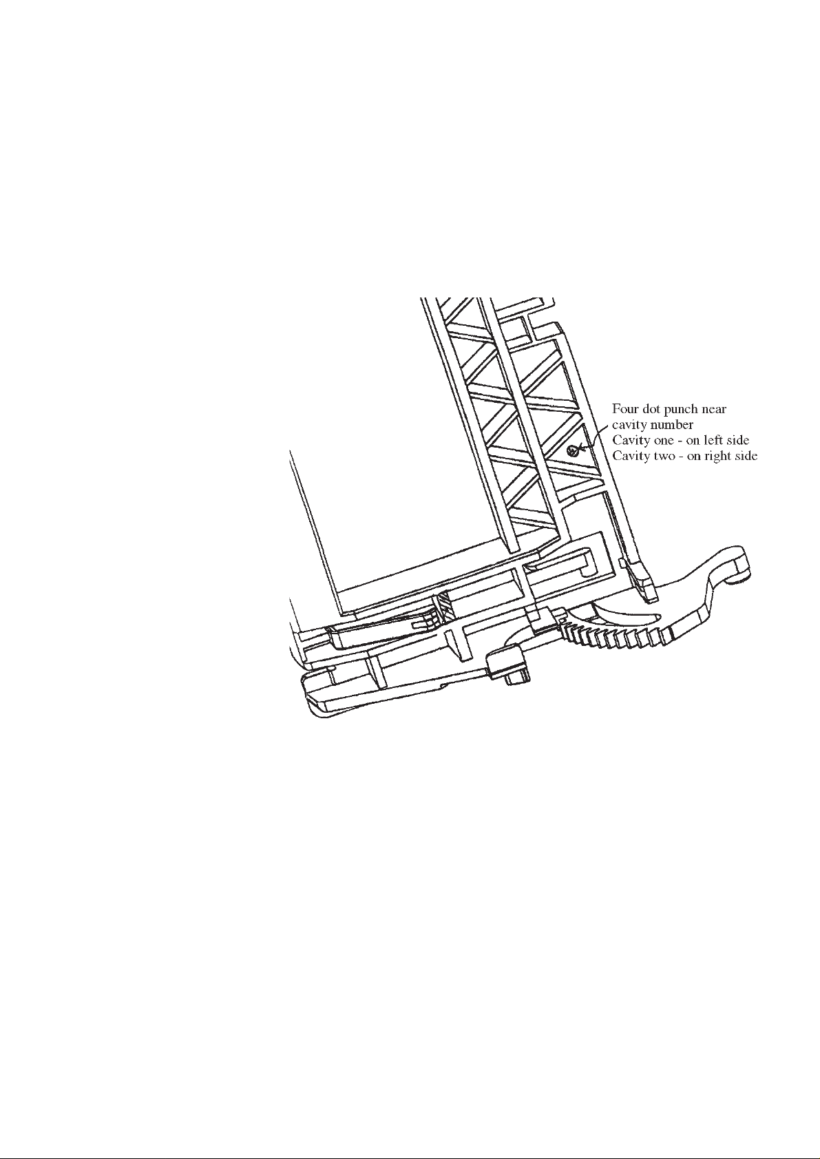
01.17 TYPENUMBER(S): FW322C, FW332, FW352C, FW391C, MC130
SYMPTOM : Cassette door stucks with cassette during eject.
CURE : The problem is due to deformation of cassette door’s plastic spring
causing the cassette to interfere with tape deck capstan during eject.
For repair the cassette door must be replaced by the improved
cassette door.The improved cassette door can be recognized by 4
dots near the cavity number (see picture below).
REMARKS : The service stock at PCS has been checked and is OK.
Only improved cassette doors will be delivered.
Service code number reads 4822 443 10173.
01.18 TYPENUMBER(S): FW322C, FW342C, FW352C, FW372C, FW391C, FW392C, FW395C
SYMPTOM : CD Tray opens half way.
CURE : The cause is due to switch bracket (pos 123) jammed.
Improvement on switch bracket has been done to have more
clearance between switch bracket and pcb & the fixation boss.
For repair only the switch bracket (12NC:4822 402 10085) needs to
be replaced.
REMARKS :
Service Newsletter 1997 – Audio Systems 5/8
Page 47

01.19 TYPENUMBER(S): FW360C
SYMPTOM : The display shows “NO DISC” although some discs are already
loaded.
CURE : Add a capacitor 330nF (12NC: 5322 121 42661) across the “Play-
position-over” switch (pos 82).This is done by soldering the capacitor
across the 2 tracks of the 4cm x 1cm pc board on the right side of the
CD Changer unit (see Service Manual chapter 4-5, figure2 - pc board
above & behind gear C or pos 6).
REMARKS :
01.20 TYPENUMBER(S): FW610, FW620C, FW630, FW650C, FW680V
INFORMATION : Service Manual, Electrical par tslist
Following parts are added to the electrical partslist:
4822 320 11804 Flexwire 15p Combi Board
↔ Control Board
4822 320 11805 Flexwire 19p Combi Board ↔ CD Interface Board
4822 320 11872 Flexwire 17p Combi Board ↔ Karaoke Board
REMARKS :
01.21 TYPENUMBER(S): TS6902
INFORMATION : Correction to Service Information A93-566:
In sets produced after week 9314, new CDM assembly
4822 691 30333 should be used. This CDM assembly cannot replace
4822 691 20794 in the previous production sets.
If 4822 691 20794 is not available, we suggest to repair the CDM
assembly with the service parts given on page 32 of service manual
4822 725 24131.
REMARKS :
01.22 TYPENUMBER(S): Compact Disc drives CDM12.1/15, CDM12.3BLC
INFORMATION : Standardization of failure descriptions
For indication of the main parts exploded views and unifor m item
descriptions have been created.
For drawings and general information see next pages.
REMARKS :
Service Newsletter 1997 – Audio Systems 6/8
Page 48
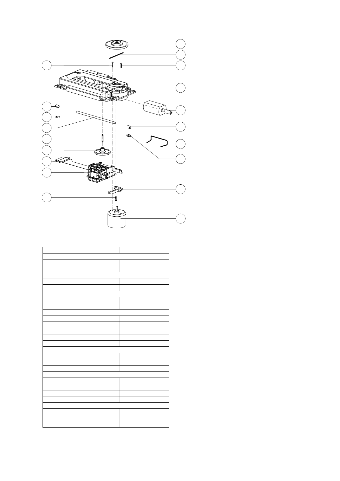
COMPACT DISC DRIVE CDM12.1/15 – 4822 691 30278 FOR ORIENTATION ONLY
18
16
10
12
19
5
6
13
20
4
17
15
1
7
9
8
11
3
14
TECHNICAL SPECIFICATION CDM12.1/15 HANDLING RECOMMENDATIONS
• Storage in dusty environments should be avoided.
• To avoid damage of the light pen assembly by electrostatic
discharges, measuring equipment and operators must be
grounded during handling.
• Contamination of the objective lens will influence the
performance. Avoid fingerprints on the lens.
• The actuator with lightpath has been adjusted carefully
during manufacturing. Avoid high forces on this part.
Do not disassemble or re-adjusted
• The laserbeam may damage the human eye. Do not look
directly into the objective lens.
• Fast heating up (e.g. by bringing the CDM from a cold
place into a warm and humid room) can result in moisture
condensating on the lens, thus influencing the playability
for a certain time. Before checking the performance the
CDM should acclimatize for at least 30 minutes.
PARTSLIST
1 Mounting plate
3 Inner-switch
4 Screw 2x8 plastite Torx
5 Spindle (gearwheel)
6 Gearwheel
7 Slide motor
8 Clamping bracket
9 Sleeve (spindle)
10 Sleeve (spindle)
11 Clamping plate (spindle)
12 Clamping plate (spindle)
13 Clamping (shortcircuit flexfoil)
14 Turntable motor
15 Screw M2x3 TORX
16 Screw M2x3 TORX
17 Turntable support ring
18 Turntable assembly
19 Spindle
20 Light pen assembly
Remark: The CDM12.1/15 is only available as complete
assembly, and as such not repaired. This sheet
is published for standardized descriptions of
failure causes, only.
Focus/radial tracking actuator
Working area:
focus
radial tracking
DC sensitivity:
focus
radial tracking
AC sensitivity (200Hz):
focus
radial tracking
Resonance frequency:
focus
radial tracking
Coil resistance:
focus
radial tracking
Laser diode
Laser wavelength (30°C)
Max. power intensity out of lens
Nom. laser current
Slide motor
Motor type
Resistance (20°C)
Starting voltage in application
Disc readout diameter
Turntable motor
Motor type
Resistance (20°C)
Operating voltage in application
CDM12.1/15
±0.5mm
±0.6mm
0.8mm/V ±20%
0.35mm/V ±20%
0.28N/A ±20%
0.32N/A ±20%
30Hz ±4Hz
49Hz ±7Hz
18Ω ±15%
18Ω ±15%
780nm ±20nm
≤0.5mW
60mA (90mA max.)
Matsushita PPN13
13.8Ω ±10%
0.6V typ. (1.2V max.)
47.4
...117.5mm typ.
RF-310T-11400
11Ω ±8%
≥1.8V
Service Newsletter 1997 – Audio Systems 7/8
Page 49
10
19
26
11
13
1
3
2
4
21
8
33
23
6
20
9
12
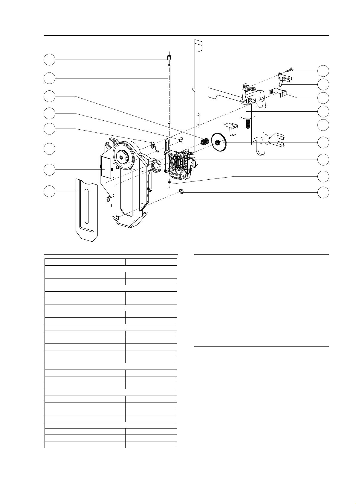
TECHNICAL SPECIFICATION CDM12.3BLC PARTSLIST
Remark: The CDM12.3BLC is only available as complete assembly,
and as such not repaired. This sheet is published for
standardized descriptions of failure causes, only.
1 Mounting plate assy
2 Ornam. plate assy
3 Turntable + motor
4 Screw M1.6x8 Torx
6 Gearwheel
8 Clamping bracket
9 Sleeve (spindle)
10 Sleeve (spindle)
11 Clamping plate (spindle)
12 Clamping plate (spindle)
13 Contact spring (earth)
19 Spindle
20 Light pen assembly
21 Earth spring
23 Pivot spring
26 Idler wheel
33 Slide motor assembly
HANDLING RECOMMENDATIONS
• Storage in dusty environments should be avoided.
• To avoid damage of the light pen assembly by electrostatic
discharges, measuring equipment and operators must be
grounded during handling.
• Contamination of the objective lens will influence the
performance. Avoid fingerprints on the lens.
• The actuator with lightpath has been adjusted carefully
during manufacturing. Avoid high forces on this part.
Do not disassemble or re-adjusted
• The laserbeam may damage the human eye. Do not look
directly into the objective lens.
• Fast heating up (e.g. by bringing the CDM from a cold
place into a warm and humid room) can result in moisture
condensating on the lens, thus influencing the playability
for a certain time. Before checking the performance the
CDM should acclimatize for at least 30 minutes.
Focus/radial tracking actuator
Working area:
focus
radial tracking
DC sensitivity:
focus
radial tracking
AC sensitivity (200Hz):
focus
radial tracking
Resonance frequency:
focus
radial tracking
Coil resistance:
focus
radial tracking
Laser diode
Laser wavelength (30°C)
Max. power intensity out of lens
Nom. laser current
Slide motor
Motor type
Resistance (20°C)
Starting voltage in application
Disc readout diameter
Turntable motor
Motor type
Resistance (20°C)
Operating voltage in application
CDM12.3BLC
±0.5mm
0.35mm min.
1mm/V ±20%
0.24mm/V ±20%
0.16N/A ±20%
0.25N/A ±20%
30Hz +7Hz
49Hz ±5Hz
7.1Ω ±15%
18Ω ±15%
780nm ±20nm
≤0.5mW
36mA (47mA max.)
FF-030PK-08250
13.8Ω ±10%
0.6V typ. (1.2V max.)
47.4
...117.5mm
RF-410CH-12250
5.7Ω ±8%
0.5V typ.
COMPACT DISC DRIVE CDM12.3BLC – 4822 691 30487 FOR ORIENTATION ONLY
Service Newsletter 1997 – Audio Systems 8/8
 Loading...