

Page 1

For internal use only PHILIPS
ISSUE 96.09 (96-12-13)
Published by:
Service Depar tment BG Audio
09.01 TYPENUMBER(S): AS440, AS445, AS450, AS455, AS540, AS545, AS550, AS640,
AS641, AS642, AS645, AS650, AS655, AZ6820, AZ6821, AZ6822,
AZ6823, AZ6825, AZ6827, AZ6830, AZ6831, AZ6832, AZ6833,
AZ6834, AZ6835, AZ6836, AZ6839, AZ6840, AZ6841, AZ6843,
AZ6844, AZ6845, AZ6846, AZ6847, AZ6848, AZ6850, AZ8040,
CD60, CD70, CD80, CD91, CD163, CD165, CD410, CD690/2x,
CD692/2x, CD710, CD720, CD730, CD732, CD733, CD740, CD750,
CD910, CD911, CD920, CD921, CDC263, CDC265, CDC745,
CDC751, CDC794, CDC796, CDC915, CDC916, CDC925, CDC926,
CDC935, CDC936, CS1600, CS2600, FW14, FW15, FW20, FW21,
FW30, FW31, FW36, FW40, FW41, FW54, FW56, FW66, FW70,
FW76, FW80
INFORMATION : Additional to Newsletter issue 58 (95-04-07) concerning CDM12.1
and CDM12.3 modules: objective lens cleaning.
The cleaning solvent “Kodak lens cleaner CAT 176 71 36” is available
in most photoshops.
ALCOHOL MAY NOT BE USED for plastic lenses.
REMARKS :
09.02 TYPENUMBER(S): AW7560
INFORMATION : Service Manual,Tape Deck partslist
The type number of the motor is changed to M9T90U24-T.
Service code is 4822 361 10888.
REMARKS : Design changed since production start.
09.03 TYPENUMBER(S): AW7760
INFORMATION : Service Manual, Elecrical partslist
L4 of AW7760/11 is changed to fixed inductor 0.47µH.
Service code is 4822 157 10686.
REMARKS : Design changed since production start.
SERVICE NEWSLETTER
BG Audio Service Newsletter 1996 1/13
Page 2

09.04 TYPENUMBER(S): AZ1000
INFORMATION : Service Manual, Exploded View diagram
The Magnet (4822 526 10659) is not drawn on the exploded view
diagram. It is located under item 23 4822 401 11641, Clamper.
REMARKS :
09.05 TYPENUMBER(S): AZ1307, AZ1308, AZ1407, AZ1508
INFORMATION : Service Manual, Recorder Module, Electrical partslist
2715 and 2722 are changed from 22nF to 33nF to improve ALC
distortion at strong signal.
2733 is changed from Tubular type to Mylar capacitor to improve high
temperature characteristic of bias modulation.
2732 is changed from 3.3nF to 4.7nF to increase the bias oscillation
level.
item Service code Description
––––––––––––––––––––––––––––––––––––––––––––––
2715 4822 126 13174 Cer Tub. 33nF 30% 50V
2722 4822 126 13174 Cer Tub. 33nF 30% 50V
2732 4822 126 11714 Cer Tub. 4.7nF 20% 50V
2733 4822 121 43144 Cap Poly 22nF 10% 50V
REMARKS : Modifications are implemented in production from week 9638
onwards.
09.06 TYPENUMBER(S): AZ2600, AZ2605, AZ2615
INFORMATION : Service Manual,Tape Board, Electrical partslist
2721 is changed from Tubular type to Mylar capacitor to improve high
temperature characteristic of bias modulation.
2722 is changed from 3.3nF to 4.7nF to increase the bias oscillation
level.
item Service code Description
––––––––––––––––––––––––––––––––––––––––––––––
2721 4822 121 43144 Cap Poly 22nF 10% 50V
2722 4822 126 11714 Cer Tub. 4.7nF 20% 50V
REMARKS : Modifications are implemented in production from week 9638
onwards.
BG Audio Service Newsletter 1996 2/13
Page 3

09.07 TYPENUMBER(S): AZ2805, AZ2808
INFORMATION : Service Manual, Recorder Module, Electrical partslist
2721 is changed from Tubular type to Mylar capacitor to improve high
temperature characteristic of bias modulation.
2722 is changed from 3.3nF to 4.7nF to increase the bias oscillation
level.
item Service code Description
––––––––––––––––––––––––––––––––––––––––––––––
2721 4822 121 43144 Cap Poly 22nF 10% 50V
2722 4822 126 11714 Cer Tub. 4.7nF 20% 50V
REMARKS : Modifications are implemented in production from week 9638
onwards.
09.08 TYPENUMBER(S): AZ2805, AZ2808
SYMPTOM : The CD drawer does not open or close.
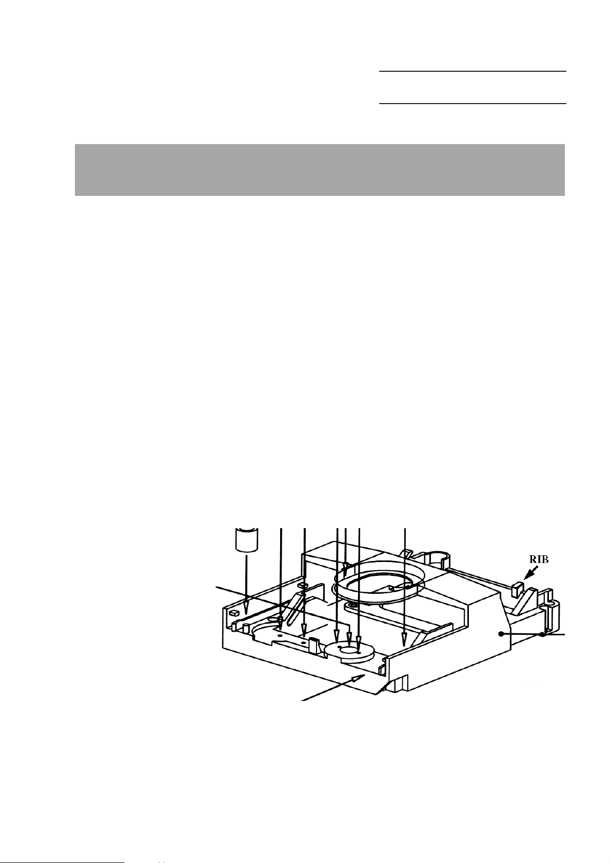
CURE : The ECO Short Loader is out of position at the rear fixing slot.
This fault might be caused when the set has been dropped.
Shor
t term and service solution:
Add brackets to the rib at both sides of the ECO Short Loader
Chassis (item 206).
The parts are available via following ser vice codes:
4822 420 10641 Bracket
4822 502 11473 Screw M3x8
4822 505 10758 Nut M3
Mount the bracket with screw and nut as shown in the drawing on
next page.
Long term solution:
Ribs will be added on the rear cabinet to strengthen the bracket for
holding the ECO Short Loader.
REMARKS : It is advised to add the brackets in every set, brought in for repair,
with production stamp before week 9642.
New Rear Cabinet will be implemented in production from week 9645
onwards.
BG Audio Service Newsletter 1996 3/13
Page 4
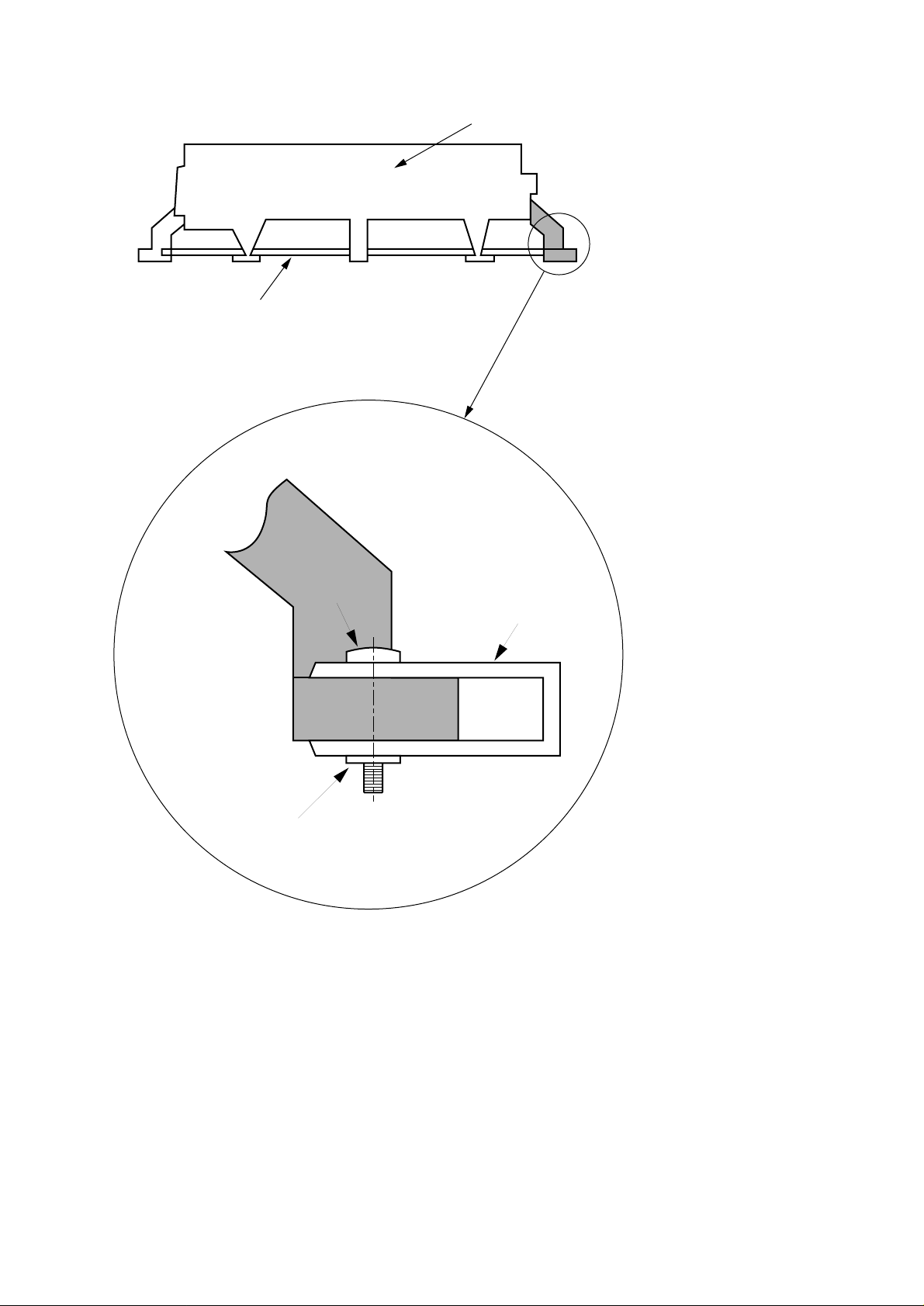
MOUNTING OF BRACKET
x2
206 Chassis (back view)
ECO-SL
Printed Circuit Board
Screw
M3x8
Bracket
Stainless steel
Nut M3
Zoom
BG Audio Service Newsletter 1996 4/13
Page 5

09.09 TYPENUMBER(S): AZ3805, AZ3808
INFORMATION : Service Manual, MTF Module, Electrical partslist
The recording bias oscillation level is too low.
Change the capacitor 2732 from 3.3nF to 4.7nF (4822 126 11714).
REMARKS : Modifications are implemented in production from week 9638
onwards.
09.10 TYPENUMBER(S): AZ6820, AZ6821, AZ6822, AZ6823, AZ6825, AZ6827, AZ6830,
AZ6831, AZ6832, AZ6833, AZ6834, AZ6835, AZ6836, AZ6837,
AZ6839, AZ6840, AZ6841, AZ6843, AZ6844, AZ6845, AZ6846,
AZ6847, AZ6848, AZ6850, AZ6856, AZ6858
INFORMATION : Above mentioned sets use CD mechanism
CDM12.3B (4822 691 30335) or CDM12.3BL (4822 691 30359).
The CDM might be exchanged because the guide block (linear
toothed bar) is out of position. It has too much play.
REMARKS : Guide block has been modified and the new guide block has been
introduced from production week 9611 onwards.
In the beginning, the CDM with a modified guide block can only be
recognized from the week code printed on the label sticked on the
CDM. Later on, the colour of the guide block is changed from black
into white. Only CDM12.3 marked 9611 and higher should be applied.
09.11 TYPENUMBER(S): AZ6830, AZ6831, AZ6832, AZ6833, AZ6839, AZ6840, AZ6841
INFORMATION : The Battery Door is available with service code number
4822 444 60911.
REMARKS :
09.12 TYPENUMBER(S): AZ8050, AZ8051, AZ8052, AZ8055, AZ8056, AZ8057, AZ8061,
AZ8068, AZ8150, AZ8262, AZ8267, AZ8268
INFORMATION : The Recording Lever (pos. 506) is now available with service code
number 4822 402 10651.
REMARKS :
BG Audio Service Newsletter 1996 5/13
Page 6

09.13 TYPENUMBER(S): AZ8050, AZ8051, AZ8052, AZ8055, AZ8056, AZ8057, AZ8061,
AZ8068, AZ8150, AZ8262, AZ8267, AZ8289
INFORMATION : During production, the Clamper Disc Assembly is changed.
Followings are the service codes of the two Clamper Disc
assemblies.
Original Clamper Disc Assembly (Soft disc):
Item 407 4822 532 51871 Pressure Ring Assy
Item 411 4822 535 60096 Disc
New Clamper Disc Assembly (hard disc):
Item 407 4822 532 12412 Pressure Ring Assy
Item 411 4822 466 93464 Disc
REMARKS : Both Clamper Disc Assemblies will be used in production.
NOTE:THIS INFORMATION IS NOT VALID FOR /..D VERSIONS.
09.14 TYPENUMBER(S): AZ8349
INFORMATION : Service Manual, Mechanical partslist
The Cassette Door is assembled of two parts:
Item 4 Cassette Door Assy (R):
4822 256 10318 Cassette Door Holder (R)
4822 443 64604 Cassette Door Cover (R)
Item 5 Cassette Door Assy (L):
4822 256 10317 Cassette Door Holder (L)
4822 443 64603 Cassette Door Cover (L)
REMARKS :
09.15 TYPENUMBER(S): AZ9055
INFORMATION : Service Manual, Mechanical partslist – Cabinet
Following parts are added to the service partslist:
Item 2 4822 454 13181 Badge (Philips)
2 4822 454 13179 Badge (Magnavox)
8 4822 442 00306 EQ Cover
22 4822 529 10317 Damper for Cass. Door
22 4822 466 93504 Damper for CD Door (for all versions)
34 4822 410 10429 EQ Knob (A) - 100 Hz
34 4822 410 10431 EQ Knob (B) - 1 kHz
34 4822 410 10432 EQ Knob (C) - 10 kHz
Electrical partslist:
IC551 PT2249A can be replaced by TC9149P (4822 209 61529).
REMARKS :
BG Audio Service Newsletter 1996 6/13
Page 7

09.16 TYPENUMBER(S): CDC771V
INFORMATION : Service manual
The published service code number of the flat cable (WS03) is not
correct.The service code number should read 4822 320 11791.
REMARKS :
09.17 TYPENUMBER(S): FR731, FR751
SYMPTOM : Tuner does not receive any radio stations.
CURE : On the tuner board, the crystal X101 does not operate because the
loading capacitors C150 and C151 are not matched with the crystal
and IC103.
Change C150 and C151 from 33pF to 18pF (4822 122 31061).
REMARKS : Modification is implemented in production from week 9635 onwards.
09.18 TYPENUMBER(S): FR731, FR732, FR751, FR752
INFORMATION : The Posistor Assembly (CN302) which is loose mounted on the
Mains Transformer is now available with service code number
4822 117 12656.
REMARKS :
09.19 TYPENUMBER(S): FW11
INFORMATION : Service Manual, Mechanical partslist
The CD Clamper assembly consists following parts:
Item 204 4822 462 72062 Magnet Holder Cover
206 4822 256 02249 Magnet Holder
241 4822 526 10667 Magnet Ring Plate
REMARKS :
09.20 TYPENUMBER(S): ND7500
INFORMATION : Version ND7500/46 was introduced since December 1993.
For repair infor mation please refer to service manual
ND7500/48/59 (4822 725 24549) except the Cassette Door (L), which
is available with ser vice code number 4822 444 60944.
REMARKS :
BG Audio Service Newsletter 1996 7/13
Page 8

09.21 TYPENUMBER(S): ND7600, RD7060
INFORMATION : Service Manual, Mechanical partslist
The Cassette Door is assembled of two parts:
Item 4 Cassette Door Assy (R):
4822 256 10318 Cassette Door Holder (R)
4822 443 64604 Cassette Door Cover (R)
Item 5 Cassette Door Assy (L):
4822 256 10317 Cassette Door Holder (L)
4822 443 64603 Cassette Door Cover (L)
REMARKS :
BG Audio Service Newsletter 1996 8/13
Page 9

For internal use only PHILIPS
ISSUE 96.09 (96-12-13)
Published by:
Service Depar tment BG Audio SERVICE NEWSLETTER
09.22 TYPENUMBER(S): AE1595
INFORMATION : ADDITIONAL INFORMATION TO SERVICE INFORMATION A96-550
4822 303 14019 Aerial
4822 443 10344 Battery Cover
4822 101 11476 Volume Control
4822 267 31921 Earphone Jack
4822 240 10145 Speaker 2.25" 8 ohm
REMARKS :
09.23 TYPENUMBER(S): AE1695
INFORMATION : ADDITIONAL INFORMATION TO SERVICE INFORMATION A96-550
4822 303 14021 Aerial
4822 443 10345 Battery Cover
4822 101 21248 Volume Control
4822 267 31921 Earphone Jack
4822 240 10146 Speaker 2.25" 4 ohm
REMARKS :
09.24 TYPENUMBER(S): AE2140, AE2145
INFORMATION : ADDITIONAL INFORMATION TO SERVICE INFORMATION A96-550
4822 303 14018 Aerial
4822 443 10326 Battery Cover
4822 101 11458 Volume Control
4822 146 10505 Transformer 120V
4822 146 10504 Transformer 230V
4822 146 10515 Transformer 120/230V
4822 498 10586 Handle
4822 240 10142 Speaker R102 4 ohm
4822 276 13763 Push Switch (POWER)
4822 267 31468 Earphone Jack
4822 209 62192 IC TA7368P
4822 267 30738 Mains Socket (VDE)
4822 265 20706 Mains Socket (UL)
4822 277 21794 Voltage Selector
REMARKS :
PRODUCT SURVEY
BG Audio Service Newsletter 1996 9/13
Page 10

09.25 TYPENUMBER(S): AE6545
INFORMATION : ADDITIONAL INFORMATION TO SERVICE INFORMATION A96-550
4822 443 10319 Battery Cover
4822 101 11457 Volume Control
4822 267 31862 Headphone Jack
4822 242 10423 Headphone AY3655 w/winder
REMARKS :
09.26 TYPENUMBER(S): AE6550
INFORMATION : ADDITIONAL INFORMATION TO SERVICE INFORMATION A96-550
4822 443 10321 Battery Cover
4822 101 11457 Volume Control
4822 267 31862 Headphone Jack
4822 240 10141 Speaker 40mm 7 ohm
4822 242 10423 Headphone AY3655 w/winder
REMARKS :
09.27 TYPENUMBER(S): AE6745
INFORMATION : ADDITIONAL INFORMATION TO SERVICE INFORMATION A96-550
4822 423 41275 Battery Cover
4822 102 10472 Volume control
4822 466 10677 Zebra connector
4822 410 10534 Rubber Keypad
4822 267 31863 Headphone Jack
4822 135 00051 LCD Display
4822 242 10423 Headphone AY3655 w/window
REMARKS :
09.28 TYPENUMBER(S): AJ3140
INFORMATION : ADDITIONAL INFORMATION TO SERVICE INFORMATION A96-550
4822 423 41163 Battery Cover
4822 101 21256 Volume Control
4822 146 10451 Transformer 120V
4822 146 10452 Transformer 120V White
4822 146 10448 Transformer 230V
4822 146 31456 Transformer 120/230V
4822 146 10514 Transformer 240V BS
4822 146 10679 Transformer 240V SAA White
4822 410 10398 Knob-Clock Function
4822 410 10417 Knob-Clock Function White
4822 209 32851 IC LM8562
4822 130 90817 Display LTC637D1G
4822 276 13577 Tact Switch
4822 240 10118 Speaker 2.5" 8 ohm
4822 272 10225 Voltage Selector
REMARKS :
BG Audio Service Newsletter 1996 10/13
Page 11

09.29 TYPENUMBER(S): AQ6340
INFORMATION : ADDITIONAL INFORMATION TO SERVICE INFORMATION A96-550
4822 443 10279 Battery Cover
4822 492 11097 Cassette Door Spring
4822 443 10278 cassette Door
4822 100 20868 Volume Control
4822 450 10111 Lens-Cassette
4822 458 10518 Grille-speaker
4822 410 10456 Knob-Voice Act.
4822 134 10031 Knob-BNS
4822 277 11526 Contact-Switch
4822 240 10151 Speaker 36mm 8 ohm
4822 242 10366 Mic KUB2823
4822 265 10504 Phone Jack (Green)
4822 265 10505 Mic Jack (Black)
4822 265 10506 DC Jack
4822 276 13726 Switch-Push 4P2T
4822 277 11527 Switch-Slide 2P3T
4822 277 11528 Switch-Slide 1P2T
4822 349 11012 Counter
4822 358 10165 Counter Belt
4822 691 10496 Tape Deck
4822 249 10525 R/P Head
4822 249 10524 E. head
4822 361 10837 DC Motor
REMARKS :
09.30 TYPENUMBER(S): AQ6463
INFORMATION : ADDITIONAL INFORMATION TO SERVICE INFORMATION A96-550
4822 443 10383 Battery Cover
4822 492 11196 Cassette Door Spring
4822 443 10384 Cassette Door
4822 101 11459 Volume Control
4822 443 10385 Door Insert
4822 450 10165 Lens-cassette
4822 401 11629 Belt Clip
4822 410 10601 Knob-DBB
4822 265 10506 DC Jack
4822 267 31861 Headphone Jack
4822 277 11579 Switch-Slide DBB
4822 242 10441 Headphone AY3660
REMARKS :
BG Audio Service Newsletter 1996 11/13
Page 12

09.31 TYPENUMBER(S): AQ6547, AQ6567
INFORMATION : ADDITIONAL INFORMATION TO SERVICE INFORMATION A96-550
4822 443 10378 Battery Cover
4822 492 42743 Cassette Door Spring
4822 443 11382 Cassette Door (PHI)
4822 443 10379 Cassette Door (MVX)
4822 101 11429 Volume Control
4822 401 11627 Belt Clip
4822 442 00445 Cassette Door Cover
4822 450 10164 Cassette Lens
4822 462 10769 Rubber Keypad
4822 267 31862 Headphone Jack
4822 265 10662 DC Jack
4822 691 10516 Tape Deck MCT-7
REMARKS :
09.32 TYPENUMBER(S): AQ6560
INFORMATION : ADDITIONAL INFORMATION TO SERVICE INFORMATION A96-550
4822 443 10308 Battery Cover
4822 492 42743 Cassette door spring
4822 459 04171 Front Cabinet Assy (PHI)
4822 449 80074 Front Cabinet Assy (MVX)
4822 101 11429 Volume Control
4822 401 11627 Belt Clip
4822 492 11172 Cassette Spring Plate
4822 267 31862 Headphone Jack
4822 691 10516 Tape deck
Following parts are for blue colour versions only:
4822 443 10452 Battery Cover
4822 443 10465 Cassette Door (PHI)
4822 443 10453 Cassette Door (MVX)
4822 401 11649 Belt Clip
4822 492 11336 Cassette door Spring
REMARKS :
BG Audio Service Newsletter 1996 12/13
Page 13

09.33 TYPENUMBER(S): AQ6562
INFORMATION : ADDITIONAL INFORMATION TO SERVICE INFORMATION A96-550
4822 443 10328 Battery Cover
4822 492 11186 Cassette Door Spring
4822 443 10327 Cassette Door
4822 101 11459 Volume Control
4822 401 11629 Belt Clip
4822 381 11743 Dial Lens
4822 410 10554 Knob-DBB
4822 209 13626 IC MM1104CF
4822 265 10621 DC Jack
4822 267 31861 Headphone Jack
4822 277 11566 Switch-Slide DBB
4822 242 10441 Headphone AY3660
4822 691 10528 Tape Deck
REMARKS :
09.34 TYPENUMBER(S): AQ6563
INFORMATION : ADDITIONAL INFORMATION TO SERVICE INFORMATION A96-550
4822 443 10328 Battery Cover
4822 492 11186 Cassette Door Spring
4822 443 10381 Cassette Door
4822 101 11459 Volume Control
4822 401 11629 Belt Clip
4822 381 11756 Dial Lens
4822 458 10545 Grille-Speaker
4822 410 10554 Knob-DBB
4822 209 13626 IC MM1104CF
4822 265 10621 DC Jack
4822 267 31861 Headphone Jack
4822 277 11566 Switch-Slide DBB
4822 240 10151 Speaker 36mm 8 ohm
4822 242 10441 Headphone AY3660
4822 691 10528 Tape Deck
REMARKS :
BG Audio Service Newsletter 1996 13/13
Page 14

For internal use only PHILIPS
ISSUE 97.08 (96-10-16)
Published by:
Service Depar tment BG Audio
08.01 TYPENUMBER(S): AE3350
SYMPTOM : IC1 is defective.
CURE : IC1 is probably damaged by wrong polarity while using the AC/DC
adaptor. IC1 CXA1019S is available via service code
4822 209 15034. Following text is added into IFU (via addendum) as
a temporary solution.
You can connect the set to the mains using a mains adaptor.
• Make sure that the local voltage corresponds to the voltage
of the 3V adaptor.
Important!
• The 2.1 mm centre pin of the 5.5mm adaptor plug must be set
to minus pole, as indicated under the 3V DC IN socket.
• Connect the mains adaptor to the 3V DC socket of the set and
plug the mains adaptor into a wall socket.
The battery supply will now be disconnected.
• Always disconnect the mains adaptor if you are not using it.
Note: Remove the batteries if you intend to operate the set
permanently on the mains supply.
For long term, protection circuitry will be added to prevent IC1
damage caused by wrong polarity supply.
REMARKS : Addendum had been added for sets produced from week9634
onwards.
SERVICE NEWSLETTER
BG Audio Service Newsletter 1996 1/6
Page 15
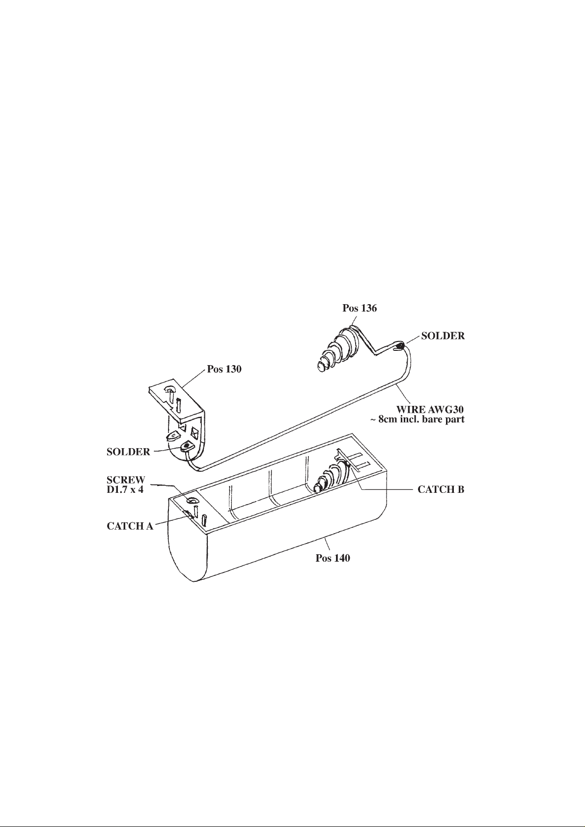
08.02 TYPENUMBER(S): AQ6613, AQ6619
INFORMATION : The battery holder pos. 191 service code: 4822 256 60325 in PCS
does not come a wire soldered between the spring connection
pos.136 and one of the contacts pos.123.
For this reason it becomes necessary that during replacement of this
part, the technician must solder this additional piece of wire.
Material: Any Black wire of thickness AWG30 cut to length of 8cm
including the bare portion at both ends.
Steps:
1. Unscrew D1.7 x 4 and remove pos.130 by uncatching at catch A
2. Remove pos. 136 by uncatching at catch B
3. Solder the wire as indicated in picture 1
4. Reassemble pos. 130 and pos. 136 into the Battery holder pos.140
5. Dress the wire such that it does not obstr uct the batter y inser tion
(into the small groove provided and if necessar y hold it down with
a small tape).
See next drawing:
REMARKS :
08.03 TYPENUMBER(S): AZ1101, AZ1102
SYMPTOM : CD SEARCH has no function and replaced by SKIP function.
CURE : When we start the CD and press PLAY button before reading the
TOC, there will be possible that the CD SEARCH function will be
deleted and be replaced by SKIP function even when the SEARCH
button was keep pressing. When the CD is restart, symptom may not
be reproduced.
REMARKS :
BG Audio Service Newsletter 1996 2/6
Page 16

08.04 TYPENUMBER(S): AZ7260, AZ7261, AZ7262, AZ7263, AZ7264, AZ7265, AZ7266,
AZ7267, AZ7268, AZ7360, AZ7361, AZ7362, AZ7363, AZ7364,
AZ7365, AZ7366, AZ7367, AZ7461, AZ7464, AZ7465, AZ7466,
AZ7467
SYMPTOM : Set skips tracks/slide motor does not turn in PLAY-mode.
The phenomenon mainly occurs at low temperatures (< -10 C).
CURE : Reason:
Conceptual failure of the set. In PLAY-mode the gain of the
slide servo control loop is too low. The gain depends on a software
parameter of the CD7 (set by the microprocessor), the gain of the
servo driver, temperature behaviour of slide motor and friction of gear.
In worst case (low gain of servo driver / low impedance of slide
motor) the set can already be inoperative at ambient temperature !!
During production only selected servo driver / CD-drive combinations
are in use. In addition the low pass filter of the slide motor control
loop has been redesigned.
As long term solution the software will be changed.
Microprocessors with software versions ≤v70 already cover all
tolerance problems.
Note: Software version numbers are counted downwards.
That means the lower the number, the newer the software.The
software version is displayed when entering the ser vice test program.
Cure: Because selection can not be done in the ser vice field and
upgrading of the microprocessor is rather expensive following service
strategy has been worked out:
In case of defective servo driver or defective CD-drive and software
version >v70
• replace defective par t
• solder resistor 12Ω in parallel to slide motor
(simulates low temperature)
• enter PLAY-mode and check slide movement
(watch tooth wheel of slide motor)
• if slide does not move or still skips tracks modify low pass filter
(if not already carried out)
pos. 3817 → 470Ω (4822 051 20471)
pos. 3818 → 0Ω (4822 051 20008)
pos. 2817 → 47nF (4822 122 32542)
pos. 2818 → 47nF (4822 122 32542)
• repeat PLAY-test
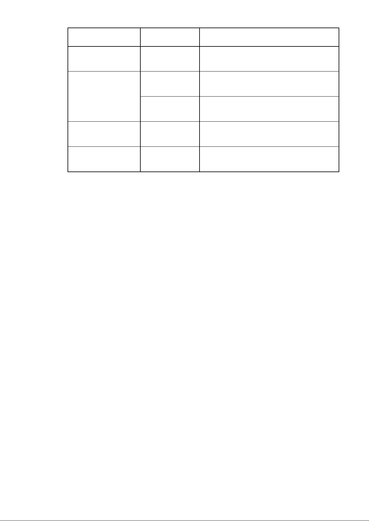
• if set is still inoperative upgrade microprocessor (see table below)
• desolder resistor 12Ω
BG Audio Service Newsletter 1996 3/6
Page 17
REMARKS :
08.05 TYPENUMBER(S): AZ8050, AZ8051, AZ8052, AZ8061, AZ8150
INFORMATION : For solving recording unstable problem, new Combi PCB (issue 4)
will be implemented in production from week 9642.
REMARKS :
08.06 TYPENUMBER(S): AZ8055, AZ8056, AZ8057, AZ8068
INFORMATION : For solving recording unstable problem, new Combi PCB (issue 7)
will be implemented in production from week 9641.
REMARKS :
08.07 TYPENUMBER(S): AZ8262, AZ8267, AZ8289
INFORMATION : For solving recording unstable problem, new Combi PCB (issue 8)
will be implemented in production from week 9642.
REMARKS :
08.08 TYPENUMBER(S): CS2600, CS2700
INFORMATION : Service Manual
Add to Specifications survey:
AUX input impedance:47kΩ
HEADPHONES output impedance: 220Ω
REMARKS :
TYPENUMBER
FACTORY
CHANGE CODE
UPGRADE MICROPROCESSOR TO
AZ7263, AZ7264 KT01 onwards
KT01 onwards
KT01 onwards
TMP47C823F-AZ7264.2 or TMP47P823VF (OTP)
software version: v70
service code: 4822 209 13566
1)
TMP47C823F-AZ7264.2 or TMP47P823VF (OTP)
software version: v70
service code: 4822 209 13566
2)
AZ7260, AZ7261, AZ7262,
AZ7265, AZ7266, AZ7267,
AZ7268
2)
KT01 only
(printed board 1)
KT02 onwards
(printed board 2)
TMP47C422F-AZ7262.2
software version: v70
service code: 4822 209 15023
AZ7360, AZ7361, AZ7362,
AZ7363, AZ7364, AZ7365,
AZ7366, AZ7367
TMP87CK20AF-AZ7466.3
software version: v69
service code: 4822 209 13133
AZ7461, AZ7464, AZ7465,
AZ7466, AZ7467
1)
Service stock of old processors has been cleared, only new version will be delivered.
2)
These typenumbers are produced with two different versions of the printed board.
TMP87CK20AF-AZ7466.3
software version: v69
service code: 4822 209 13133
BG Audio Service Newsletter 1996 4/6
Page 18

08.09 TYPENUMBER(S): ESA-mode, general
All portable CD-players with CDM12.3B, CDM12.3BL and
CDM12.3BLC in ESA-mode (double speed application)
SYMPTOM : Set skips tracks or mutes in ESA-mode (double speed), memor y is
not filled-up properly. In normal play-mode with ESA off (single
speed) the set operates without problems.
CURE : Bearing of turntable motor is worn out (lifetime problem).
Replace CDM12.3B (4822 691 30335), CDM12.3BL
(4822 691 30359) resp. CDM12.3BLC (4822 691 10487).
REMARKS : The phenomenon can hardly be reproduced and even might
disappear in vertical playing position. In case of customer complaints
the sets should always be checked in both, ESA and non-ESA-mode.
08.10 TYPENUMBER(S): FR310, FR320, FR330, FR340
INFORMATION : The microprocessor, item 7471 TMP47C870N, marked with stamp
“TUNLEU-C3-C” (service codenumber 4822 209 31507) is not longer
available.
A new microprocessor is available with the same service codenumber
4822 209 31507 but this is an OTP version with the following text
TMP47P870N with hand-written marked “M3 310”.
If this type of µP is used we have to add 4 pull down resistors (10kΩ)
on this µP (item 7471).
1 resistor 10kΩ on pin 14 to ground
1 resistor 10kΩ on pin 15 to ground
1 resistor 10kΩ on pin 16 to ground
1 resistor 10kΩ on pin 17 to ground
REMARKS : A problem is the power consumption of this type OTP.
The backup batteries have to deliver 2.5mA to the µP if the set is
switched off, so the batter ies will be empty much faster as before.
When the batteries are empty only the clock looses the time.
Pre-set memory stays OK.
08.11 TYPENUMBER(S): FW56
INFORMATION : Correction of Parts list in Service Manual and newsletter 96.04.22.
4822 426 51751 = Philips Front without Karaoke for FW56/20/22/25
4822 426 51752 = Philips Front with Karaoke for FW56/21/21M/30
REMARKS :
BG Audio Service Newsletter 1996 5/6
Page 19

08.12 TYPENUMBER(S): FW610, FW620C, FW630, FW650C, FW680V
INFORMATION : Additional information to newsletter item 96.07.11.
Service Information with repair hints and faultfinding guide concerning
the Power management of the above mentioned sets is available now.
For FW610 use Service Information A96-363.
For FW620C use Service Information A96-364.
For FW630 use Service Information A96-365.
For FW650C use Service Information A96-366.
For FW680V use Ser vice Information A96-367.
REMARKS :
BG Audio Service Newsletter 1996 6/6
Page 20

For internal use only PHILIPS
ISSUE 96.07 (96-08-30)
Published by:
Service Depar tment BG Audio
07.01 TYPENUMBER(S): AS440, AS445, AS450, AS540, AS545, AS550, AS555, AZ1307,
AZ1308, AZ1407, AZ1508, AZ2805, AZ2808, AZ8640, FW17, FW18,
FW24, FW26, FW46, FW47, FW66, FW76, FW330, FW331, FW610,
FW630
SYMPTOM : CD Drawer does not open or close because items 202 & 204 have
been damaged.
CURE : The root cause of the problem is the insufficient guidance of the
drawer that can jump over the gear wheel 202, such that the drawer
cannot be closed completely. If the drawer is pulled or pushed, the
cam gear will be damaged.
Two guiding-brackets items 503 & 504 have been added at item 216
(tray).Also the pinion gear 213 has been modified.
These actions reduce the risk of misalignment or damage to gear
wheel 202 and the cam gear 204 when the CD tray is pulled or
pushed.
REMARKS : This information concerns module called “Short Loader” and “ECO
Short Loader”. These modules have been applied in all above
mentioned sets and this phenomenon may occur. This infor mation
also refers to newsletter publications issue 64.40, 65.01 and
96.06.05. In newsletter 65.01 was also the typenumber FW33
included. However in this set a 3 disc changer is applied and not the
short loader module.
07.02 TYPENUMBER(S): AZ3705, AZ3708
INFORMATION : Service Manual
Add to electrical parts list:
Add capacitor 2869 22µF 20% 50V (4822 124 41596) which is
accidentally left out of the CDC-7 Module parts list.
For AZ3708/01:
Item 215 Front cabinet should be 4822 459 04261
instead of 4822 459 04125.
Item 216 Window display should be 4822 381 11763
instead of 4822 381 11719.
For AZ3705 & AZ3708:
Item 280 Door Battery should be 4822 443 10397
instead of 4822 423 41277.
REMARKS :
SERVICE NEWSLETTER
BG Audio Service Newsletter 1996 1/8
Page 21

07.03 TYPENUMBER(S): AZ3708/01
INFORMATION : Change of Tuning grid frequency
The procedure on changing the Tuning grid frequency published in
the service manual on page 2-4 has been changed.
The new procedure is as follows:
1. Switch on the unit
2. Press and hold the BAND button for 5 seconds, the display will
show “Grid 9” or “Gr id 10” depending on the last grid setting.
REMARKS :
07.04 TYPENUMBER(S): AZ8048, AZ8348
INFORMATION : Service Manual
Add to mechanical parts list:
The mounting screw (item 101) for new CD Mechanism
KSM-2101BDM, is available via ser vice code 4822 502 21383.
REMARKS :
07.05 TYPENUMBER(S): AZ8061, AZ8068
INFORMATION : Service Manual, Mechanical partslist:
The service ordernumber for item 444 “BUTTON SET CD”
4822 410 63658 as already published in the Service Manual
concerns a standardized black coloured part.
On special request the original green metallic lacquered button set
has been taken on stock.This part can be ordered with service code
number 4822 410 10802 “button set CD green metallic”.
REMARKS :
BG Audio Service Newsletter 1996 2/8
Page 22

07.06 TYPENUMBER(S): AZ8340, AZ8350, AZ8351, AZ8352, AZ8440, AZ9040, AZ9338,
AZ9340, AZ9350
INFORMATION : Service hint RCD drive mechanism
Analyses of exchanged RCD drives in service workshops showed
that a reasonable quantity of these drives has no fault and is
according to specifications.
For sets equipped with CD1-D module (produced from week 9452
onwards) the following faults may occur:
• COLD or BROKEN SOLDER JOINTS in the areas of connectors
1801 and 1802 and bridge wires connecting the vertical bended
board with the tact switches.
Due to handling during exchanging the disc drive, a bad solder joint
may be temporarily reconnected. So it seems that the exchange
was successful but after some time the set may fail again.
• MARGINAL FOCUS SEARCH TRIANGLE AMPLITUDE
In case the set does not start-up due to FOCUS-error the following
actions have to be done:
Check whether the amplitude of the electrical triangle signal during
FOCUS SEARCH is too low.
Use for this service testprogram, measuring point “3” in
schematic diagram.
If FOCUS cannot be found in the normal position of the set, then
turn set upside down and try again (Gravity influences focus coil).
If FOCUS will now be found the electronic circuit has to be changed
to increase the amplitude of the triangle signal.
Change 3816 to 68kΩ 4822 116 52297
3819 to 3.3kΩ 4822 116 83864
3820 to 100kΩ 4822 116 83878
3924 to 2.7kΩ 4822 116 52263
Delete 3818
REMARKS : These changes were implemented in production from approx.June
1995 onwards.
07.07 TYPENUMBER(S): FR731, FR751
INFORMATION : Service Manual, electrical parts list
The type of IC303 is TDA7313D with SO-28 package.
The service code should read 4822 209 14856.
The type of IC305 is NJM2177AF with QFP package.
The service code should read 4822 209 14929.
REMARKS :
BG Audio Service Newsletter 1996 3/8
Page 23

07.08 TYPENUMBER(S): FW372C/21, FW362/21/21M & FW395C/21
INFORMATION : Tuning Grid for MW band
Due to Software bug, sets produced between week 9627 and 9644
will not be able to switch between 9kHz and 10kHz as descr ibed in
the instruction for use (Operation Manual).
For this reason the tuning grid is set according to the destination
countries by the manufacturer. In case a set was purchased outside
the country, the tuning grid can be changed by hardware adaptation.
This is done by adding or deleting resistor 3157 100kΩ 5% 0.5W
(4822 116 52234).
By adding 3157 the tuning grid becomes 9kHz
By deleting 3157 the tuning grid becomes 10kHz
With the resistors 3157 added the Software will recognize the Tuner
version as “CHI”instead of “OSC” and the new Service frequencies
loaded during the Service Test Program are as follows:
Preset Frequency
1 87.5 MHz
2 108 MHz
3 531 kHz
4 1602 kHz
5 558 kHz
6 1494 kHz
7 87.5 MHz
8 87.5 MHz
9 87.5 MHz
10 98 MHz
11 87.5 MHz
REMARKS : For the purpose of identification a new stroke version will be created
during this period to identify between 9kHz and 10kHz
9kHz = /21 & /21M
10kHz = /41 & /41M
This information concerns sets produced between week 9627 and
week 9644 only.
07.09 TYPENUMBER(S): FW12
SYMPTOM : Too much mechanical noise (whistling) during CD play.
CURE : The problem is due to a “hissing” noise which can be annoying to
some customer.Problem is resolved by adding a capacitor 2.2nF
across resistor 3830.
REMARKS :
BG Audio Service Newsletter 1996 4/8
Page 24

07.10 TYPENUMBER(S): FW15
INFORMATION : Service manual, Mechanical partslist
The service code number for AM Aerial Frame with JST connector
reads 4822 303 50082 and applied in FW15.
The service code number for AM Aerial Frame with loose wires reads
4822 158 60622.This par t is not applied in this set but in other sets.
REMARKS :
07.11 TYPENUMBER(S): FW610, FW620C, FW630, FW650C
INFORMATION : Service manual
Additional information to circuit description Power Board of above
mentioned typenumbers.
PREREGULATION (primary control):
• The Power Board is equipped with a primar y control.
The purpose of this circuit is:
a. Smaller transformer. The power board has to supply nominal
power at nominal mainsvoltage -10%.The transformer has to
withstand nominal mainsvoltage +10% as well.Some countries have
more than 10% overvoltage.
Normally this difference will be converted into heat, (higher
temperature).
With the primary control circuit it is possible to adjust the
mainsvoltage at about 180V (=nominal voltage -20%).This is done by
cutting the top of the sine wave with a FET. This means that the
mainstransformer is supplied with a “stabilized” mainsvoltage of about
180V respectively 90V for /17 version (USA). This saves about 20%
loss.
b. In case of high current consumption (overtemperature), the circuit
has the possibility to reduce the mains voltage.This reduces the
temperature as well.
c. In Standby mode the circuit operates reducing the mainsvoltage to
about 90V.This results in a stand-by power consumption less than
3W (with switched off display).
REMARKS : A faultfinding method about this Primary control circuit is in
preparation.
07.12 TYPENUMBER(S): FW630, FW650C, FW680V
INFORMATION : Service Manual, partslist
The flexfoil-connector (17 fold) item 1830 reads 4822 267 51465.
REMARKS :
BG Audio Service Newsletter 1996 5/8
Page 25

07.13 TYPENUMBER(S): MC150
INFORMATION : Service Manual
Add to Mechanical partslist:
The ordering code for Cover, Cassette door item 306 reads
4822 442 00579.
REMARKS :
07.14 TYPENUMBER(S): General
INFORMATION : ESD (ELECTR
O STATIC DISCHARGE) PREVENTION
Attention has to be paid to the ESD phenomenon.
Find on next pages a copy of page 5 and 6 of Ser vice Link magazine
June 1996, distributed by Philips Consumer Electronics, Euroser vice,
which contains an article about ESD.It is recommended to use this
information in service workshops.
DURING REPAIR ESD CAN OCCUR WHICH DESTROYS
COMPONENTS AND/OR DEGENERATES COMPONENTS OR
CIRCUITS IN SUCH A WAY THAT SOONER OR LATER
MALFUNCTIONS WILL OCCUR.
BE AWARE OF THE ESD RISKS.
Prevention of ESD starts with being aware of the ESD risks.Stick to
the following rules:
1. Keep all ESD sensitive components in ESD protective packing
material when not in use.
2. ESD sensitive equipment, brought in for repair, must be
processed in an ESD protected working area with (at least) an
earthed dissipative mat. Persons should wear a wr ist strap and be
connected to earth.
REMARKS :
BG Audio Service Newsletter 1996 6/8
Page 26
What is ESD?
ElectroStatic Discharge is a spark
jumping from one conductive
surface, charged with static
electricity, to another conductive
surface. This incredible fast
movement of static charge can have
disastrous consequences, especially
for electronic circuitry. We, humans,
only feel ESD at a discharge of
about 3,000 Volts. However many
semiconductors can be damaged by
a discharge of just 60 Volts or less.
What causes ESD?
Static electricity occurs whenever
two substances are rubbed together
or separated from each other. On
non-conducting materials, such as
plastics and textiles, charges remain
stationary and cannot discharge and
are therefore called static charges.
Static electricity is present
throughout our environment. Static
charges are brought in by people
and are generated during their
normal movements. Clothing and
articles of common plastic are
prime generators of static charges,
even people walking generate
charges from the sliding and
separation of their shoes from the
floor.
How does ESD affect electronics?
ESD between people and
components or products often
damages hardware and software. It
can even cause catastrophic failure.
In hardware ESD can degrade the
product by overheating components
or by causing “punch-through”. In
software ESD can cause failures
such as false triggering and
distortion of clock pulses in logic
circuits. In a few cases it can even
completely disable the component
or circuit. However, in many more
cases the comonent or circuit
remains operational but is
degenerated in such a way that
sooner or later malfunctions will
occur. This phenomenon is called
“latent failure”.
“Whenever electronic components
are assembled, static electricity lies
in wait,” says Ger Frankenmolen,
consultant in electrostatic discharges
with Novatronics, part of Philips
Components. “Although strict
standards are in place to minimise
damage due to ESD, advances in
technology continue to throw up
problems. Tackling these is
something which must be done
throughout the production process
and it is my job to put the
appropriate precautions in place”. 2
What you should know about ESD!
It can damage almost any
consumer electronic product!
Annually, millions of dollars are lost world-wide by the
phenomenon of ESD (ElectroStatic Discharge), the invisible
micro-lightning which damages sensitive electronic components
and circuits. This article explains what ESD is and how its effects
can be controlled.
Typical electrostatic voltages
Means of Low relative High relative
static generation humidity humidity
Walking across carpet 35,000 V 1,500 V
Walking over vinyl floor 12,000 V 250 V
Work at bench 6,000 V 100 V
Vinyl envelopes 7,000 V 600 V
Common poly bag picked up from bench 20,000 V 1,200 V
Work chair padded with urethane foam 18,000 V 1,500 V
When such a static charge is induced to a nearby conductor
(e.g. our skin), the charge can jump to that conductor in a nanosecond:
this is an ESD!
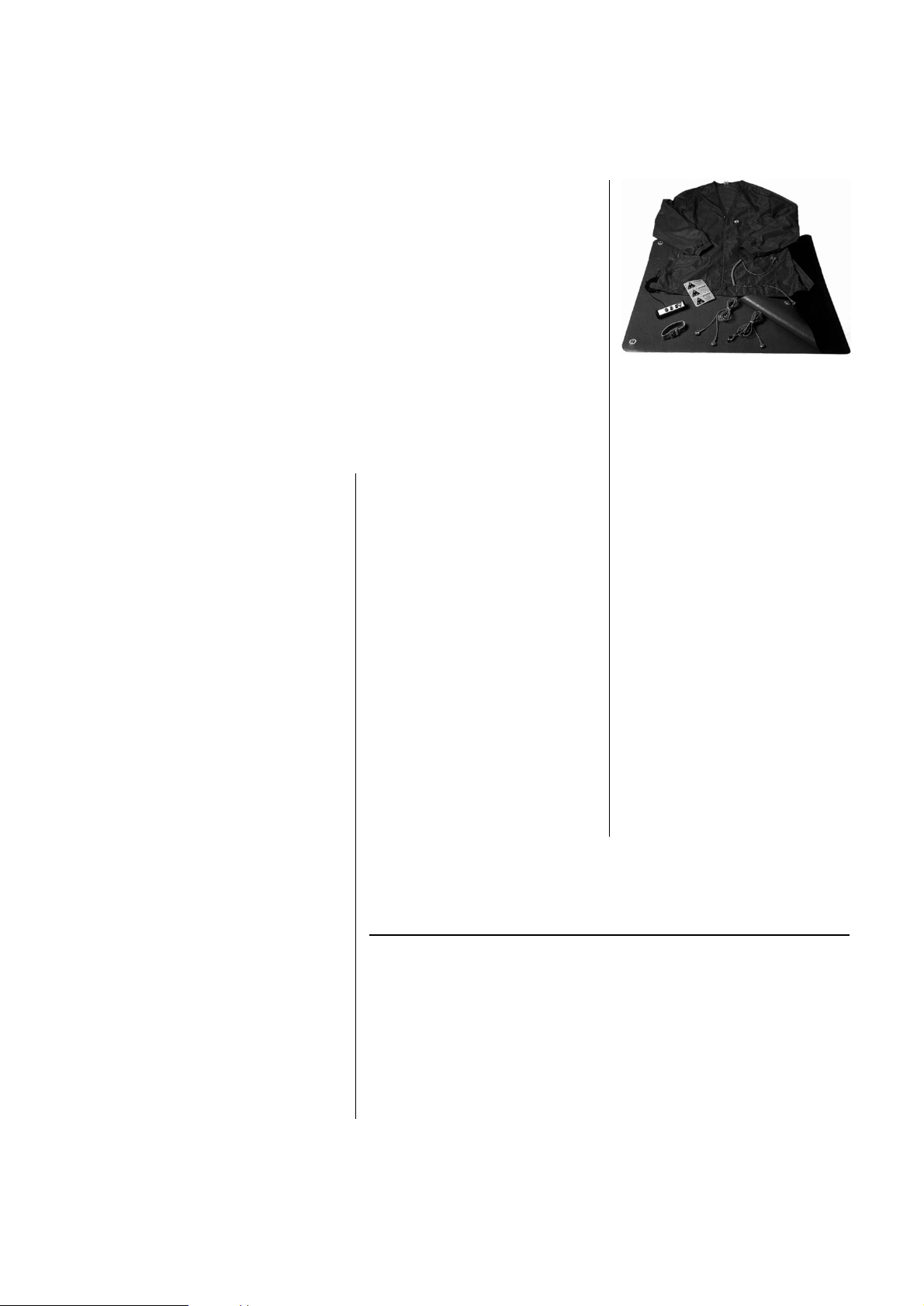
Philips Service offers a range of
equipment and accessories to help
prevent ESD.
BG Audio Service Newsletter 1996 7/8
Page 27
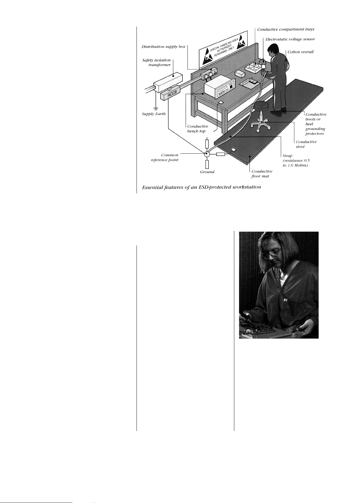
How to prevent ESD
and ESD damage
Static electricity cannot be
eliminated, but it can be kept under
control. Charging can be prevented
by an appropriate grounding system
for people and objects that may
come into contact with the
component or product. Preventing
ESD is relatively simple. It starts
with training everybody in the
workshop: make people aware of
the ESD dangers and stick to the
following rules:
1 All consumer electronic (CE)
products being brought in for
repair must be kept in ESD
protective packing material when
not in use.
2 All CE products being brought in
for repair must be processed in
an ESD protected working area
with an earthed dissipative mat.
Peolple should wear a wrist strap
and be connected to earth. 9
Philips Service has the following
equipment and aids available to
make your working environment an
ESD safe working place:
1 Connection box 4822 320 11307
Key item in your ESD set.This box has 3 press
stud connections and can easily be attached to a
work bench.Comes with 3m of cable.
Resistance 1 MOhm.
2 Anti-static 4822 395 10223
wrist band
With press stud.Anti allergic . Resistant to hot
water. Small metallic strip inside is isolated so
that only tiny metal threads are in contact with
the skin.Wrist band resistant to a minimum of
10 machine washes (40°C, no bleach).
Resistance 0 Ω.
3 Extendible cable 4822 320 11305
2m cable with press studs.Connects wrist band
to connection box.
Resistance 2 MΩ.
4 Anti-static table mat
With 4 connecting press-studs:
1200 x 650 x 1.25 mm
4822 466 10953
600 x 650 x 1.25 mm 4822 466 10958
Consisting of two different flexible materials.
Top layer (blue) surface resistance =
107-109Ω/square,bottom layer (black) surface
resistance = 104-105Ω/square.
5 Connecting cable 4822 320 11306
3m cable with press studs.Connects table mat
to connection box.
Resistance 2 MΩ.
6 Earth cable 4822 320 11308
with Mueller clip (3m)
Connects any product to ESD mat or
connection box.Press button at one end and
Mueller clip at the other end.
Resistance 1 MΩ
KIT ESD3 4822 310 10671
Complete kit combining all six prior products
(small table mat) above and ESD warning
stickers for the complete ESD solution for any
work station.
Wristband tester 4822 344 13999
Tests anti-static functioning of the wrist band.
Works on 9V battery (included).There are three
test outcomes:green light “PASS” lights when
the resistance of the circuit (wrist band and
cable together) is between 0.5 and 10 MΩ.Red
light “FAIL” blinks and some beeps are heard
when the resistance is below 0.5 MΩ or above
10 MΩ.In this case the wrist band and cable can
not be used in this combination.Other
combinations can be tried.Yellow light “LOW
BATTERY” lights when the battery needs
changing.
Anti-static jacket 4822 395 10224
Allows hands free working in ESD environment.
Tiny carbon threads contained inside the textile.
The Philips approved anti-static
jacket is lightweight and cool.
Perfect for hands fr ee working
The press buttons for connection to the
connection box or anti-static table mat are placed
on both side pockets on an extra strong textile to
avoid tear damage.Surface resistance of the OFX100 fabric is 105Ω/square.This textile gives a very
constant resistance all over the jacket and allows a
discharge from 1000V to 100V in less than 0.1 sec.
This textile (93% polyester, 7% “B ASF RESISTAT”
conducting fibres) allows long life (washing 30°C,
no bleach) and weighs only 77 gr/m2.
What ESD control equipment is available?
BG Audio Service Newsletter 1996 8/8
Page 28

For internal use only PHILIPS
ISSUE 96.06 (96-06-28)
Published by:
Service Depar tment BG Audio
06.01 TYPENUMBER(S): AE3650
SYMPTOM : FM sensitivity is too low.
CURE : FM IF is shifted because it might occur that it is not properly aligned
in production: In some cases the input signal for IF-alignment was too
strong.
Re-align FM IF following the procedure in the service manual.
Use weak input signal to avoid mis-alignment.
REMARKS : From week 9546 onwards, the alignment procedure at production is
strictly controlled by using weak input signal.
06.02 TYPENUMBER(S): AJ3920, AW7150, AW7250, AZ2100, AZ2600, AZ8350, AZ8351,
AZ8352, AZ8357, AZ9350, AZ9355
INFORMATION : In above mentioned sets, the output pins LED and BIAS of item 8110
are not used. From week 9621 onwards, a 4-pins socket is used in
the position of 8110. Consequently resistors 3103 and 3105 are also
deleted.
REMARKS :
06.03 TYPENUMBER(S): AJ3920
INFORMATION : Item 2309 is changed from 1000µF/10V to 1000µF/16V
(4822 124 40201) to safeguard enough safety margin.
REMARKS : Modification is implemented in production from week 9620 onwards.
06.04 TYPENUMBER(S): AQ6524, AQ6542
INFORMATION : The IC BA3528FP is now available via ser vice code 4822 209 13503.
This IC can also be added to service information A96-550 (Spare part
codenumbers for Service Category I products).
REMARKS :
SERVICE NEWSLETTER
BG Audio Service Newsletter 1996 1/14
Page 29

06.05 TYPENUMBER(S): AS450, AS455
SYMPTOM : CD Drawer does not open or close because items 202 & 204 have
been damaged.
CURE : The root cause of the problem is the insufficient guidance of the
drawer that can jump over the gear wheel 202, such that the drawer
cannot be closed completely. If the drawer is pulled or pushed, the
cam gear will be damaged.
Two guiding-brackets items 503 & 504 have been added at item 216
(tray).Also the pinion gear 213 has been modified. These actions
reduce the risk of misalignment or damage to gear wheel 202 and the
cam gear 204 when the CD tray is pulled or pushed.
For more infor mation see newsletter publication issue 64.40 and
65.01.
REMARKS : This modification has been implemented in production from week
9610 onwards.
06.06 TYPENUMBER(S): AW7140
INFORMATION : Cloth Speaker Grilles 4822 458 30648 and 4822 458 30649 are no
longer available. It is suggested to replace the cloth grills by Metal
Grilles 4822 458 40565 (for “L”) and 4822 458 40566 (for “R”).
REMARKS :
06.07 TYPENUMBER(S): AW7520
INFORMATION : The cassette deck type TK20FX-SW is now available via service code
4822 691 10493.
REMARKS :
06.08 TYPENUMBER(S): AZ2100, AZ2600
INFORMATION : In order to improve the accuracy of the regulated output voltage,
following changes have been introduced:
Diode 6304 has been changed to BZX79-F3V3 (4822 130 32806)
Resistor 3253 has been changed from 560Ω to 470Ω
(4822 116 52224)
REMARKS : Modification has been implemented in production from week 9611
onwards.
BG Audio Service Newsletter 1996 2/14
Page 30

06.09 TYPENUMBER(S): AZ2600
INFORMATION : Correction service manual
Following modifications have been implemented since production
start.
• Capacitor 2711 and 2712 have been changed from 220µF to
47µF (4822 124 41397) to improve low frequency over-load.
• Capacitor 2724 has been changed from 470pF to 680pF
(5322 122 32052) for controlling bias frequency to 73kHz ±1kHz.
• Resistor 3708 has been changed from 82kΩ to 68kΩ
(4822 116 52297) to improve Rec/Play distor tion.
REMARKS :
06.10 TYPENUMBER(S): AZ2600
INFORMATION : Service manual; added to Tape board partslist.
The motor of the cassette mechanism has been changed from
EG-530AD-9B to EG-530YD-9BH (4822 361 21592) in order to
improve starting torque. Following components have been added on
the cassette board to match the change of motor.
2703 4822 124 41397 Cap.47µF/25V
3703 4822 116 52176 Resistor 10Ω
3705 4822 116 83863 Resistor 1kΩ
3758 4822 100 20165 Potm.trim 500Ω
Tape speed adjustment:
Adjust 3758 instead of the potmeter inside the motor.
REMARKS : Changes have been implemented in production since production
start.
06.11 TYPENUMBER(S): AZ6827
INFORMATION : The Button Set-STOP 4822 410 62757 is not available. It can be
replaced by 4822 410 62754.
For colour matching reason, the following substitutions are
suggested:
Button Set-PLAY, 4822 410 62758 is replaced by 4822 410 62755,
Eject Button, 4822 410 62752 is replaced by 4822 410 62751.
REMARKS :
06.12 TYPENUMBER(S): AZ6827
INFORMATION : As the Front Panel 4822 444 30473 is no longer available, it can be
replaced by 4822 444 30472. For colour matching reason, it is
suggested to replace also the CD Door by existing CD Door
4822 444 60932.
REMARKS :
BG Audio Service Newsletter 1996 3/14
Page 31

06.13 TYPENUMBER(S): AZ6835
SYMPTOM : NiCd batteries (SBC6445) cannot be recharged in the set.
CURE : Reason for malfunction can either be:
Bad contact of accu detection springs (especially spring contact via
cabinet part) or over-discharge of NiCd batteries
(voltage on battery <0.9V).
In both cases the microcontroller will never switch on charging
because the accu_in line from the accu detection circuit remains low,
assuming no accus inserted. The solution is:
1. Replace D6252 by a SMD jumper (4822 051 20008)
2. Desolder T7282
3. Short-circuit collector/emitter line of T7282 by use of
SMD jumper (4822 051 20008)
WARNING
Above mentioned modification disables accu detection at two batter y
positions.
As a result also “normal” batteries can now be charged by the circuit,
if they are inserted in those positions.These batteries may become
leak and damage the CD-electronics.
CUSTOMERS MUST THEREFORE BE INSTRUCTED
NOT TO MIX-UP DIFFERENT BATTERY TYPES!!
REMARKS : This phenomenon has already been published in newsletter 65
and 96.04.05. However the concerned components were not
indicated clearly. It is only valid for typenumber AZ6835 and nor
for AZ6834, AZ6836 and AZ6837 because only AZ6835 is
rechargeable.
The service solution stated in this edition could not solve all
recharging complaints in the field.The new modifications will further
improve the detection behaviour.
It is possible that completely discharged accus (voltage around 0V)
cannot be recharged anymore.
For completely discharged accus an exter nal charger can be used.
If problems remain, customers should be informed to charge accus
even if the set is not in use for a longer period of time.
IMPORTANT NOTE:
It is advised to modify all sets brought-in for repair.
BG Audio Service Newsletter 1996 4/14
Page 32

06.14 TYPENUMBER(S): AZ6843, AZ6844, AZ6845
SYMPTOM : NiCd batteries (SBC6445) cannot be recharged in the set.
CURE : Reason for malfunction can either be:
Bad contact of accu detection springs (especially spring contact via
cabinet part) or over-discharge of NiCd batteries
(voltage on battery <0.9V).
In both cases the microcontroller will never switch on charging
because the accu_in line from the accu detection circuit remains low,
assuming no accus inserted. The solution is:
1. Replace D6251 by a SMD jumper (4822 051 20008)
2. Change R3275 from 470Ω to 2.2kΩ (4822 051 20222)
3. Change R3256 (4.7kΩ) and R3258 (5.6kΩ) to 22kΩ
(4822 051 20223)
4. Desolder T7280 and T7282
5. Short-circuit collector/emitter line of T7280 and T7282 by use of
SMD jumpers (4822 051 20008)
WARNING
Above mentioned modification disables accu detection at two batter y
positions.
As a result also “normal” batteries can now be charged by the circuit,
if they are inserted in those positions.These batteries may become
leak and damage the CD-electronics.
CUSTOMERS MUST THEREFORE BE INSTRUCTED
NOT TO MIX-UP DIFFERENT BATTERY TYPES!!
REMARKS : This phenomenon has already been published in newsletter 65.
The service solution stated in this edition could not solve all
recharging complaints in the field.The new modifications will further
improve the detection behaviour.
It is possible that completely discharged accus (voltage around 0V)
cannot be recharged anymore.
For completely discharged accus an exter nal charger can be used.
If problems remain, customers should be informed to charge accus
even if the set is not in use for a longer period of time.
IMPORTANT NOTE:
It is advised to modify all sets brought-in for repair.
06.15 TYPENUMBER(S): AZ6843, AZ6844, AZ6845, AZ6856, AZ6858
INFORMATION : From week 9616 onwards, 7300 CS4331-KS “H” version
(marked EYH____) has been used in production. Following changes
have been implemented in order to improve total harmonic distortion
of analogue output.
2311 and 2312 changed from 3.3nF to 1nF (4822 122 33446)
3305 and 3306 changed from 560Ω to 2.7kΩ (4822 051 20272)
3329 and 3330 changed from 33kΩ to 100kΩ (4822 051 20104)
REMARKS : In case the “old” IC is replaced by IC 4822 209 33969
(marked EYH____), the above mentioned components have to be
changed too.
BG Audio Service Newsletter 1996 5/14
Page 33

06.16 TYPENUMBER(S): AZ6846, AZ6847, AZ6848
SYMPTOM : NiCd batteries (SBC6445) cannot be recharged in the set.
CURE : Reason for malfunction can either be:
Bad contact of accu detection springs (especially spring contact via
cabinet part) or over-discharge of NiCd batteries
(voltage on battery <0.9V).
In both cases the microcontroller will never switch on charging
because the accu_in line from the accu detection circuit remains low,
assuming no accus inserted. The solution is:
1. Replace D6251 by a SMD jumper (4822 051 20008)
2. Change R3275 from 470Ω to 2.2kΩ (4822 051 20222)
3. Change R3256 (470Ω) and R3258 (560Ω) to 2.2kΩ
(4822 051 20223)
4. Desolder T7280 and T7282
5. Short-circuit collector/emitter line of T7280 and T7282 by use of
SMD jumpers (4822 051 20008)
WARNING
Above mentioned modification disables accu detection at two batter y
positions.
As a result also “normal” batteries can now be charged by the circuit,
if they are inserted in those positions.These batteries may become
leak and damage the CD-electronics.
CUSTOMERS MUST THEREFORE BE INSTRUCTED
NOT TO MIX-UP DIFFERENT BATTERY TYPES!!
REMARKS : This phenomenon has already been published in newsletter 65.
The service solution stated in this edition could not solve all
recharging complaints in the field.The new modifications will further
improve the detection behaviour.
It is possible that completely discharged accus (voltage around 0V)
cannot be recharged anymore.
For completely discharged accus an exter nal charger can be used.
If problems remain, customers should be informed to charge accus
even if the set is not in use for a longer period of time.
IMPORTANT NOTE:
It is advised to modify all sets brought-in for repair.
BG Audio Service Newsletter 1996 6/14
Page 34

06.17 TYPENUMBER(S): AZ8010, AZ8012, AZ8110, AZ8114, AZ8210, AZ8214, AZ8300,
AZ8301, AZ8304, AZ8400, AZ8404, AZ8700, AZ8704, AZ8705,
AZ8900, AZ8904, AZ9210, AZ9213, AZ9214, AZ9310, AZ9401,
AZ9510, AZ9513, AZ9514, AZ9610, AZ9613, AZ9614
INFORMATION : In above mentioned Service manuals two items of the shock-
absorber of the CD-mechanism (spring support and suspension
grommet) have been interchanged.
CORRECTION MECHANICAL PARTSLIST
––––––––––––––––––––––––––––––––––––––––––––––––––––
INTERCHANGE OF 4822 404 60471 (spring support) AND
4822 325 20138 (suspension grommet)
Typenumber interchanged item numbers
AZ8010, AZ8012 443 and 441
AZ8110, AZ8114 443 and 441
AZ8210, AZ8214 443 and 441
AZ8300, AZ8301, AZ8304 406 and 407
AZ8400, AZ9401, AZ8404 406 and 407
AZ8700, AZ8704, AZ8705 401 and 436
AZ8900, AZ8904 451 and 452
AZ9210, AZ9213, AZ9214 409 and 411
AZ9310 409 and 411
AZ9510, AZ9513, AZ9514 409 and 411
AZ9610, AZ9613, AZ9614 409 and 411
REMARKS : The shock-absorber consists of 3 parts of which above mentioned
items are interchanged. Usually the 3 parts are ordered all together,
that’s why no ser vice information will be prepared.
06.18 TYPENUMBER(S): AZ8050, AZ8051, AZ8052, AZ8061, AZ8150
SYMPTOM : Recording is unstable.
CURE : Problem is caused by high notes appearing in the music after the
ALC-elco has been almost fully charged.The recording amplifier has
high amplification for high notes and will thus intensify the problem.
Following steps give a ser vice solution.
1. Change 3264 and 3265 from 150kΩ to 330kΩ (4822 116 52272)
2. Change 3266 and 3267 from 180kΩ to 6.8kΩ (4822 116 52296)
3. Change 2258 and 2259 from 390pF to 4.7nF (4822 126 11714)
4. Remove 2282 (4822 126 11585) and connect it from
pin3 of IC7250 to the nodal point of 3264, 3266 and 2258.
5. Remove 2275 (4822 126 11585) and connect it from
pin14 of IC7250 to the nodal point of 3265, 3267 and 2259.
REMARKS : Above modification will be implemented in production from week 9626
onwards.
BG Audio Service Newsletter 1996 7/14
Page 35

06.19 TYPENUMBER(S): AZ8055, AZ8056, AZ8057, AZ8068, AZ8262, AZ8267, AZ8289
SYMPTOM : Recording is unstable.
CURE : Problem is caused by high notes appearing in the music after the
ALC-elco has been almost fully charged. The recording amplifier has
high amplification for high notes and will thus intensify the problem.
Following steps give a ser vice solution.
1. Change 3264 from 150kΩ to 330kΩ (4822 051 20334)
2. Change 3265 from 150kΩ to 330kΩ (4822 116 52272)
3. Change 3266 from 180kΩ to 6.8kΩ (4822 051 20682)
4. Change 3267 from 180kΩ to 6.8kΩ (4822 116 52296)
5. Change 2258 from 390pF to 4.7nF (4822 126 11714)
6. Change 2259 from 390pF to 4.7nF (4822 126 10223)
7. Remove 2282 and replace it by tubular cap. (4822 126 11585)
connected from pin3 of IC7250 to the nodal point of 3264, 3266
and 2258.
8. Remove 2275 and replace it by tubular cap. (4822 126 11585)
connected from pin14 of IC7250 to the nodal point of 3265, 3267
and 2259.
REMARKS : Above modification will be implemented in production from week 9626
onwards.
06.20 TYPENUMBER(S): AZ8562, AZ8567
INFORMATION : Service Manual, mechanical partslist
The service codes of item 429 and 453 are interchanged.
Correction:
item 429 should read 4822 529 10278
item 453 should read 4822 529 10257
REMARKS :
06.21 TYPENUMBER(S): AZ9055, SM6500, MS6050
SYMPTOM : A “plop” noise is recorded at the beginning and ending of a recording.
CURE : The noise is caused by the time difference between activation of the
motor switch and the record switch. The record switch is adjusted to
shorten the time difference so that problem is minimised. Situation
becomes worse because the record switch can be dislocated
afterwards. For service solution, adjust the position of the record
switch so that the switch is activated earlier.
Add glue to protect record switch getting loose.
REMARKS : Glue for fitting the switch has been added in production sets from
week 9542 onwards.
For long term, the location of the record switch has been changed.It
will be mounted near the middle of the record lever so that the time
difference can be further shortened. Modified mechanism has been
introduced in production from week 9621 onwards.
BG Audio Service Newsletter 1996 8/14
Page 36

06.22 TYPENUMBER(S): AZ9855
INFORMATION : Two types of cassette tape deck are used. Production will use
different factor y code to identify the deck:
KZ00xxxx for CDS-83FBF-27
KZ01xxxx for TK20FX-S
For details of TK20FX-S, see service information A95-560
(available via ser vice codenumber 4822 725 25403).
REMARKS : This publication will be followed by Service Information A95-560.
06.23 TYPENUMBER(S): CD210
INFORMATION : Microprocessor item 6530 service codenumber 4822 209 61894.
When ordering 4822 209 61894, an OTP 4822 900 10837 loaded
with software “MONO P113” for CD210 will be delivered.
REMARKS :
06.24 TYPENUMBER(S): CS2600, SC2060
SYMPTOM : The mains transformer is defective.
CURE : The thermal fuse of the mains transformer is blown. It is caused by
short circuit of capacitor AC31 that connects across the secondary of
transformer to ground.The problem may happen depending on the
quality of the capacitor.
After the defective transformer is replaced and whenever a set is sent
to workshop for repair, remove capacitors AC31, AC32 and AC33 that
are not necessary in circuit.
REMARKS : It is advised to remove the capacitors AC31, AC32 and AC33 in ever y
set brought-in for repair. From week 9540 onwards capacitors have
been deleted in production.
BG Audio Service Newsletter 1996 9/14
Page 37

06.25 TYPENUMBER(S): FR731, FR751, FR931, FR951, DSC950, FR920, FR930, FR940
INFORMATION : Test CD Dolby Surround 4822 395 10216
Dolby Surround sound is more and more included in todays Audio
equipment.
To measure specifications and to test Dolby Pro Logic equipment and
circuitry Philips developed a test CD for this purpose.
Below please find the composition of tracks together with a short
description of the application.
Dolby Pro Logic Test CD is available with service code
4822 395 10216.
REMARKS : Service Information A96-450 (service code 4822 725 23980)
describes the various tests to perform to check and measure Dolby
Pro Logic equipment by using above mentioned test CD.
A96-450 is an add-on to existing service manuals of Dolby Surround
equipment.
06.26 TYPENUMBER(S): FR731, FR751
INFORMATION : Service Manual, Electrical partslist
Capacitors C466 and C467 with value 4700µF/50V are now available
via service code 4822 124 42128.
REMARKS :
Track 1: Voice track to identify channels left, centre, right and
surround to check speaker connections
Track 2: 1kHz tone for electrical balance setting L/R,
Centre/Surround.
Track 3..6: Test signals from 20Hz to 20kHz to measure frequency
response, harmonic distortion, signal-to-noise ratio and
channel separation for each channel
Track 7..12: Test signals from 20Hz to 20kHz, max. 0dB CD level, to
check headroom for visible clipping for each channel.
Track 13: Unmodulated track during 30 sec. to measure S/N ratio
Track 14: Test signals from 100Hz to 7kHz to check the modified
Dolby B-type noise reduction decode characteristics in
Surround channel
Track 15..23:Test signals of 20Hz to 20kHz to enable distortion
measurements on all four channels at the same time
Track 24: Tone bursts of 1kHz during 1msec. to check the time
delay of the surround channel output
Track 25: Signal of 8.3kHz to check time delay in surround
channel by means of Lisajous phase test
Track 26: Not correlated noise on all four channels to test
temperature behaviour of output amplifiers
Track 27: Pink noise repeated in sequence L->C->R->S->L->C,
etc. to simulate the noise sequencer in the decoder to
enable the user to match speaker levels for proper
system balance
Track 28..34:Dolby Surround recorded music tracks to exper ience
Surround sound effect
BG Audio Service Newsletter 1996 10/14
Page 38

06.27 TYPENUMBER(S): FW12
INFORMATION : Service Manual, Electrical partslist
The ordering code for the Microprocessor IC 7401 on the Front/Power
board should read 4822 209 90436 instead of
4822 209 52484.
The marking on the correct IC should be “12S50950”.
REMARKS :
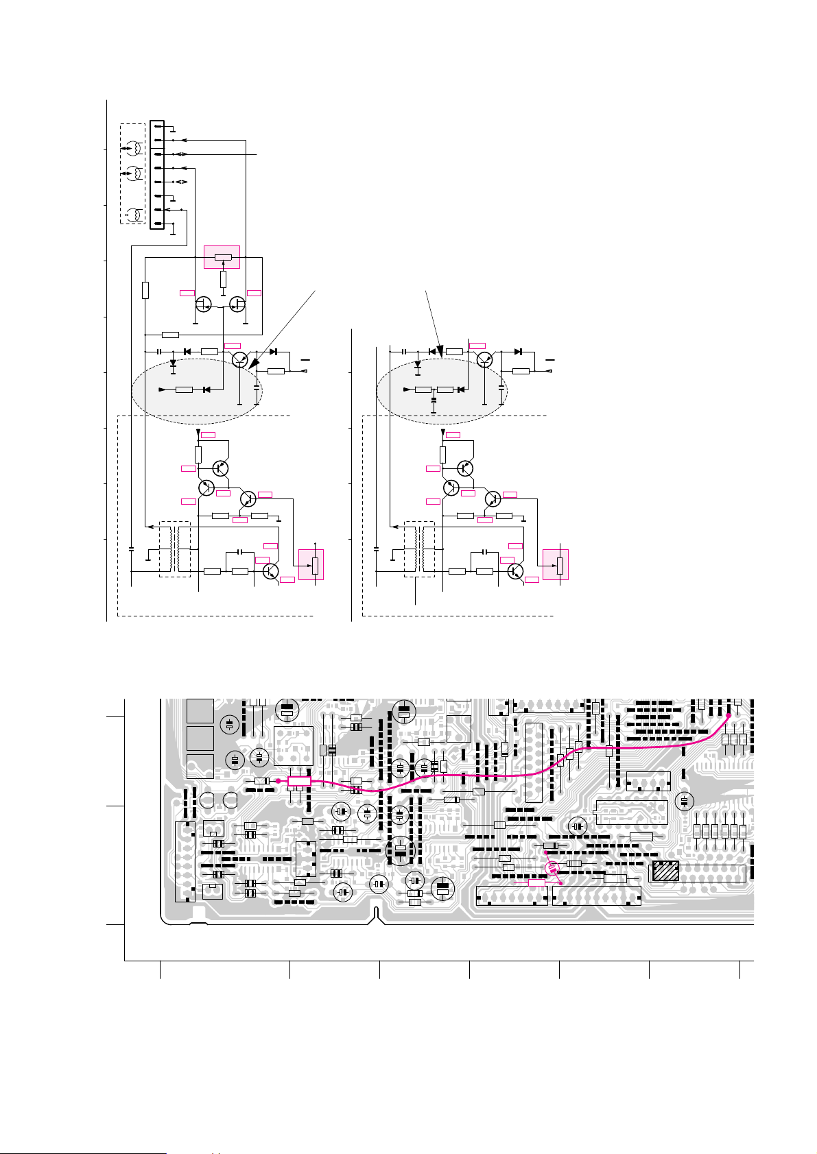
06.28 TYPENUMBER(S): FW610, FW620C, FW630, FW650C, FW670P, FW680V
SYMPTOM : Bias oscillator is not functioning properly.
CURE : In some cases it might happen that the bias oscillator is not
functioning properly. In that case an AC voltage of about 3V~ will be
measured on T162 instead of 30V~.
This phenomenon is caused by tolerances of FET J111.
To solve this problem the following actions should be performed:
1. Replace wirebr idge 9524 by resistor 10kΩ.
2. Connect an electrolytic capacitor (elcap) 22µF/50V
(4822 124 22337) with the negative pole on that side of the
resistor that is close to diode 6777.
Connect the positive pole to the wirebridge 9598.
3. Remove SMD resistor 3781.
4. Add “resistor cable” (wire with a resistor 4.7MΩ in series)
between cathode of 6778 and wirebridge 9518.
See next circuit diagram and printed board layout.
BG Audio Service Newsletter 1996 11/14
Page 39
REMARKS :
COMBI BOARD - CIRCUIT DIAGRAM
SYMM.
BIAS
LEVEL
BIAS
LEVEL
BIAS
BIAS
BIAS
Head
Erase
R
L
DECK
REC/PB
BIAS
ERASE OSCILLATOR
K
J
I
H
N
G
F
M
L
A
AA
A
A
P
A
A
AA
P
6773
1N4148
6772
1N4148
6774
1N4148
6778
1N4148
3770
1k5
3778
8R2
3776
6k8
3771
1k
1M
3780
3777
150R
3783
4k7
3784
15k
3782
4k7
3781
4M7
3779
330k
BC858C
7787
BC328-40
7782
BC856B
7784
REC
2781
10n
6n8
2782
2784
22n
100p
2786
100n
2783
33n
2787
+12V
-8V
T166
T165
T164
T163
T162
T161
5701
1
2
3
4
5
6
MT
3 2
1
10k
3773
3 2
1
100k
3785
BC848C
7783
7781
BC848C
J111
7785
J111
7786
1720
8
7
6
5
4
3
2
1
BIAS
ERASE OSCILLATOR
K
J
N
M
L
A
AA
P
P
6773
1N4148
6772
1N4148
6774
1N4148
6778
1N4148
3770
1k5
3778
8R2
3776
6k8
3771
1k
1M
3780
3777
150R
3781
4M7
3779
330k
BC858C
7787
BC328-40
7782
BC856B
7784
REC
2781
10n
6n8
2782
2784
22n
100p
2786
100n
2783
33n
2787
+12V
-30V
5701
1
2
3
4
5
6
MT
3 2
1
10k
3773
BC848C
7783
7781
BC848C
10k
22∝
original
after modification
7,9V
1,3V
0,9V
3,8V
3,3V
7,9V
10,9V
11,5V
12,0V
0V 0V
-33,6V
7,9V
1,3V
0,9V
3,8V
3,3V
7,9V
10,9V
11,5V
12,0V
-33,6V
COMBI BOARD - COMPONENTSIDE VIEW
654321
D
E
9512
9518
3896
3897
3887
9601
3857
3858
1825
9609
9613
9578
9604
9605
9606
9607
9608
9544
9531
9504
9519
4720
6792
4695
3895
9598
9899
9526
9527
9528
9571
9576
7862
3891
6777
3847
3848
2855
3580
3845
3846
1826
1828
2833
1833
9554
9559
9561
9596
9506
4709
6857
4707
4708
3656
1750
1831
1832
2694
3655
9597
9703
9789
9513
9550
9577
6760
6761
3735
3736
3761
3768
2763
2765
1829
9524
9794
979
9556
9793
3723
3717
3664
2727
2717
2693
9502
9549
9570
9792
9795
9796
9798
3715
3705
3718
3660
2761
2762
2715
2718
26422648
2711
2712
2713
2714
2722
3738
3765
6762
9501
2716
3706
9551
5632
3654
3690
36413636
2638
9702
9799
77857786
9547
9553
9557
9701
9704
6778
3733
3642
3646
2702
2703
3632
1712
1720
1730
2691
2692
2701
1711
2704
2735
4M7
10k?
22∝F/50V
BG Audio Service Newsletter 1996 12/14
Page 40

06.29 TYPENUMBER(S): FW630
INFORMATION : Service Manual
Correction of Electrical partslist on page 9-14.
Erroneously the same codenumber and description for item 7860 and
7861 has been published.
It should read:
7860 4822 209 90618 SAA7345GP/S5
7861 4822 209 32196 TDA1311AT/N2
REMARKS :
BG Audio Service Newsletter 1996 13/14
Page 41

For internal use only PHILIPS
ISSUE 96.06 (96-06-28)
Published by:
Service Depar tment BG Audio SERVICE NEWSLETTER
06.30 TYPENUMBER(S): FW68DCC
INFORMATION : In an addendum the following infor mation is added to the instruction
for use of FW68DCC:
Renumbering on a DCC Tape
The tracknumbers of the complete DCC can be checked, and if
necessary automatically corrected, if the beginning of the DCC was
marked (see “General infor mation on recording” - LEAD IN).
1. Insert the unprotected DCC that needs to be corrected.
2. Press repeatedly DCC/TAPE on the amplifier (DCC on the
remote control) until DCC appears on the display.
3. Press STOP on the DCC deck or on the remote control for more
than 2 seconds.
The “T”-message
Every time when the DCC deck marks the beginning of a track during
recording procedure (either automatic or manual) a “T” will appear on
the display.
REMARKS :
DCC
BG Audio Service Newsletter 1996 14/14
Page 42
For internal use only PHILIPS
ISSUE 96.05 (96-05-21)
Published by:
Service Depar tment BG Audio
05.01 TYPENUMBER(S): AQ4150
SYMPTOM : Defective mainstransformer.
CURE : This fault is caused by the thermal fuse.
Solution:
New transfor mer has been implemented in production;
The old transformer was marked “NC-I1887TM”
The new transfor mer is mar ked “NC-I1887TM1”
(remark: “1” is added).
The transformer is available via ser vice code 4822 146 31476.
REMARKS : This modification has been implemented in production from week
9550 onwards.This publication is a correction of newsletter 96.04.02
(Complete marked code has been offered instead of “1”).
05.02 TYPENUMBER(S): CD711
SYMPTOM : Sub-chassis (item 109) is found to be loose on the right front side.
CURE : A rib has been added onto the frame, item 110 (see draft below).
REMARKS :
SERVICE NEWSLETTER
BG Audio Service Newsletter 1996 1/3
Page 43

05.03 TYPENUMBER(S): FW12
INFORMATION : Wake-up volume adjustment
The wake-up volume level is controlled by the Microprocessor,
making it impossible to adjust the level without affecting the power
output of the set. However 2 solutions are available;
Solution 1:
Change resistors 3517/3518 from 39kΩ to 27kΩ - overall power
output will reduce by about 3dB.
Solution 2:
If the problem is only in one of the source selections it is possible to
reduce the level only for that par ticular source by reducing the input
shunt-resistors’ value.
For Tuner, reduce resistors’ 3503 and 3504 value.
For CD, reduce resistors’ 3507 and 3508 value.
For Tape, reduce resistors’ 3511 and 3512 value.
REMARKS : On Customer request this modification can be built-in.
05.04 TYPENUMBER(S): FW630
INFORMATION : Service Manual
Correction of the electrical partslist (page 9-14)
Concerning item 7860 and 7861; for both ICs the same service
codenumbers have been published.
The correct service codenumbers should read:
7860 4822 209 90618 SAA7345GP/S5
7861 4822 209 32196 TDA1311AT/N2
REMARKS :
BG Audio Service Newsletter 1996 2/3
Page 44

For internal use only PHILIPS
ISSUE 96.05 (96-05-21)
Published by:
Service Depar tment BG Audio SERVICE NEWSLETTER
05.05 TYPENUMBER(S): DCC170
INFORMATION : When in battery mode the service testmode is entered, the message
DAIO NG will be displayed (False condition).
With connected mains adapter the message reads: DAIO OK
(Good condition).
This is due to the Battery operation mode in which Digital I/O cannot
be used. In the Instructions For Use the warning “Digital I/O cannot
be used in battery mode” is already given.
REMARKS :
DCC
BG Audio Service Newsletter 1996 3/3
Page 45

For internal use only PHILIPS
ISSUE 96.04 (96-04-18)
Published by:
Service Depar tment BG Audio
04.01 TYPENUMBER(S): AE2340
INFORMATION : Additional to Newsletter 96.02.01
Sets produced with new µP are marked KZ0296xx onwards.
REMARKS :
04.02 TYPENUMBER(S): AQ4150
SYMPTOM : Defective mainstransformer
CURE : Fault is caused by the ther mal fuse.
SOLUTION:
New transfor mer has been implemented in production;
the new transfor mer is mar ked “-1”.
The transformer is available via ser vice code 4822 146 31476.
REMARKS : This modification has been implemented in production from
week 9550 onwards.
04.03 TYPENUMBER(S): AQ6446
SYMPTOM : One channel gives no sound
CURE : This fault might be caused by the headphone socket:
The headphone socket mounted slanted or cold-soldered.
SOLUTION:
Re-solder headphone socket.
Mounting procedure in production has been modified to ensure that
the socket is flat mounted on printed board panel.
REMARKS : This modification has been implemented in production from
week 9534 onwards.
SERVICE NEWSLETTER
BG Audio Service Newsletter 1996 1/9
Page 46

04.04 TYPENUMBER(S): AQ6548
SYMPTOM : Headphone interruption.
CURE : Fault might be caused by headphone wiring, which could have a dry
joint connection to speaker, because temporarily two twisted wires
have been applied with different lengths.
REMARKS : The modified headphones have been implemented in production from
week 9536 onwards.
04.05 TYPENUMBER(S): AZ6834, AZ6835, AZ6836, AZ6837
SYMPTOM : NiCd batteries (SBC6445) cannot be recharged in the set
CURE : Reason for malfunction can either be:
Bad contact of accu detection springs (especially spring contact via
cabinet part) or over-discharge of NiCd batteries (voltage on battery
<0.9V). In both cases the microcontroller will never switch on charging
because the accu_in line from the accu detection circuit remains low,
assuming no accus inserted.
The solution is:
1. Replace D6252 by a SMD jumper (4822 051 20008)
2. Change R3275 from 470Ω to 2.2kΩ (4822 051 20222)
3. Change R3256 and R3258 from 4.7kΩ to 22kΩ (4822 051 20223)
4. Desolder T7280 and T7282
5. Short-circuit collector/emitter line of T7280 and T7282 by use of
SMD jumpers (4822 051 20008)
WARNING
Above mentioned modification disables accu detection at two batter y
positions.
As result also “normal” batteries can now be charged by the circuit, if
they are inserted in those positions.These batteries may become
leak and damage the CD-electronics.
CUSTOMERS MUST THEREFORE BE INSTRUCTED
NOT TO MIX-UP DIFFERENT BATTERY TYPES!!
REMARKS : This phenomenon has already been published in newsletter 65.
The service solution stated in this edition could not solve all
recharging complaints in the field.The new modifications will further
improve the detection behaviour.
It is possible that completely discharged accus (voltage around 0V)
cannot be recharged anymore.
For completely discharged accus an exter nal charger can be used.
If problems remain customers should be informed to charge accus
even if the set is not in use for a longer period of time.
IMPORTANT NOTE:
It is advised to modify all sets brought in for repair.
BG Audio Service Newsletter 1996 2/9
Page 47

04.06 TYPENUMBER(S): AZ6834, AZ6835, AZ6836, AZ6837, AZ6843, AZ6844, AZ6845,
AZ6846, AZ6847, AZ6848
INFORMATION : The accessory SBC3546 stated in IFU and service manual is not
correct.
The car base SBC3546 cannot hold the CD portable models from
AZ6830 until AZ6850.
To mount these CD portable sets in a car, it is suggested to order car
base SBC6560 (4822 466 93339) and car base adaptor SBC6562
(4822 466 93338 for Magnavox or 4822 466 93437 for Philips
Modelnumbers).
REMARKS :
04.07 TYPENUMBER(S): AZ8049, ND6600, RD6060
SYMPTOM : The cassette door damper gear (item 14) moves out easily.
CURE : The cassette door (item 2; 4822 443 64542) has been modified by
adding a rib to prevent the gear from moving off.
REMARKS : New doors are used in production with sets marked KY02 from week
9604 onwards. Consumer Ser vice stock has been adapted.
04.08 TYPENUMBER(S): AZ8052
SYMPTOM : Crackling noise (servo noise) audible in left speaker dur ing
CD-play mode.
CURE : Add 2 wireconnections on Feature/Amplifier-board 2.
1 wire between Ground of potentiometer and Emitter 7261 and
1 wire between Emitter 7262 and Emitter 7260.
REMARKS : Phenomenon occurs only in sets with layout stage .5 of
Feature/Amplifier-board 2.
From about production week 9531 onwards the 2 wires have been
implemented in production.
04.09 TYPENUMBER(S): AZ8310, ND7500, RD7050
INFORMATION : Service manual, Mechanical partslist
The CD lens cover bracket (item 75 in exploded view diagram on
page 18) is now available via ser vice code 4822 402 10201.
REMARKS :
04.10 TYPENUMBER(S): AZ8349, ND7600, RD7060
INFORMATION : Service manual, Mechanical partslist:
The CD lens cover bracket (item 115 in exploded view diagram on
page 15-3) is now available via ser vice code 4822 402 10201.
REMARKS :
BG Audio Service Newsletter 1996 3/9
Page 48

04.11 TYPENUMBER(S): AZ9350, AZ9355, AZ9555
SYMPTOM : Distorted sound in tape playback mode after making a
CD recording.
CURE : The cause of the distortion is a poor recording quality due to a too
low bias current (below 0.3mA). A correct bias curren is about
0.36mA.The correct bias current can be achieved by changing the
oscillator transistor 7770 from BC548B to BC548C (4822 130 44196).
REMARKS :
04.12 TYPENUMBER(S): FA775
INFORMATION : Service manual, additional electrical par tslist:
Switch SR16 is available via ser vice codenumber 4822 276 11933.
REMARKS : This is a correction of newsletter 25.17.
04.13 TYPENUMBER(S): FC290, FC291
INFORMATION : Service manual, partslist
Service codenumber for blue lamp LA1 and LA2 (5V/115mA) should
read 4822 134 40829 instead of 4822 134 40952
(orange lamp).
REMARKS :
04.14 TYPENUMBER(S): FC911, FC931
SYMPTOM : Cassette cannot be ejected
CURE : It might happen that in case the set is placed as the lowest part of the
system, the cassette cannot be ejected.
Fault is caused by a war ped cassette door lever.
To solve this problem the following 2 solutions are proposed:
1. Push the upper cabinet (item 501) up by:
Loosen (not completely) the 2 screws of the top cover near the
front panel.
Push the upper cabinet up.
Fasten the two screws again.
Or:
2. Cut adhesive tape on the four cabinet-supports on the front
panel, so that the upper cabinet (item 501) is pushed up a little.
REMARKS :
BG Audio Service Newsletter 1996 4/9
Page 49

04.15 TYPENUMBER(S): FC731
INFORMATION : Service manual
Additional Partslist information
Capacitor C203 changed from 3300µF into 4700µF/40V.
New Capacitor is available via service codenumber 4822 124 81305.
REMARKS : See also service newsletter 64.32.
04.16 TYPENUMBER(S): FR400, FR410
INFORMATION : Service manual
Service Manual Tuning-button and preset-button have been added to
the mechanical partslist:
service code description
––––––––––––––––––––––––––––
4822 410 10391 button tuning
4822 410 10392 button preset
REMARKS :
04.17 TYPENUMBER(S): FR731, FR751
INFORMATION : Service manual
The capacitor C204, 0.047µF/5.5V for memory back-up is now
available via ser vice code 4822 124 80923.
REMARKS :
04.18 TYPENUMBER(S): FR931
SYMPTOM : In stand-by mode, a “buzz” is audible from the center speaker.
CURE : Add two additional mass wires from two below mentioned points to
the screw at the main board (chassis ground).
– the centre point of connector CN13 (Printed Circuit Board M74)
– Collector of Q701 (Printed Circuit Board M78)
REMARKS : This solution will not be implemented in production because
production has been stopped.
04.19 TYPENUMBER(S): FW12
INFORMATION : Service manual
The service code for the complete tape mechanism is
4822 691 20966.
When replacing the complete mechanism, the record lever pos. 119
must be exchanged with that used in the defective mechanism.
This is due to standardisation of the tape mechanism.
REMARKS :
BG Audio Service Newsletter 1996 5/9
Page 50

04.20 TYPENUMBER(S): FW18
INFORMATION : Service manual, Partslist correction
The service code for the Remote control transmitter should be
4822 218 10733 instead of 4822 218 10562.
REMARKS :
04.21 TYPENUMBER(S): FW28, FW33, FW34
INFORMATION : Service manual
The optical pickup unit for the CD mechanism is now available as
service spare par t:
- pos. 62 for FW28 and FW33
- pos. 67 for FW34
The service code is 4822 691 10482.
REMARKS :
04.22 TYPENUMBER(S): FW56
INFORMATION : Service manual, Partslist correction – Front cabinet item 200
Modelnumber Description Published servicecode Should read
––––––––––––––––––––––––––––––––––––––––––––––––––––––––––––––––––––––
FW56/20/22/25 Philips front 4822 426 51751 4822 426 51752
FW56/21/30 Philips front 4822 426 51752 4822 426 51751
(Karaoke version)
FW56/37 Magnavox front 4822 426 51753 4822 426 51753
REMARKS :
04.23 TYPENUMBER(S): FW68
INFORMATION : Service manual
Item 212 of Short loader is incorrectly coded.
Service codenumber should read 4822 402 61412 instead of
4822 691 61412.
REMARKS :
BG Audio Service Newsletter 1996 6/9
Page 51
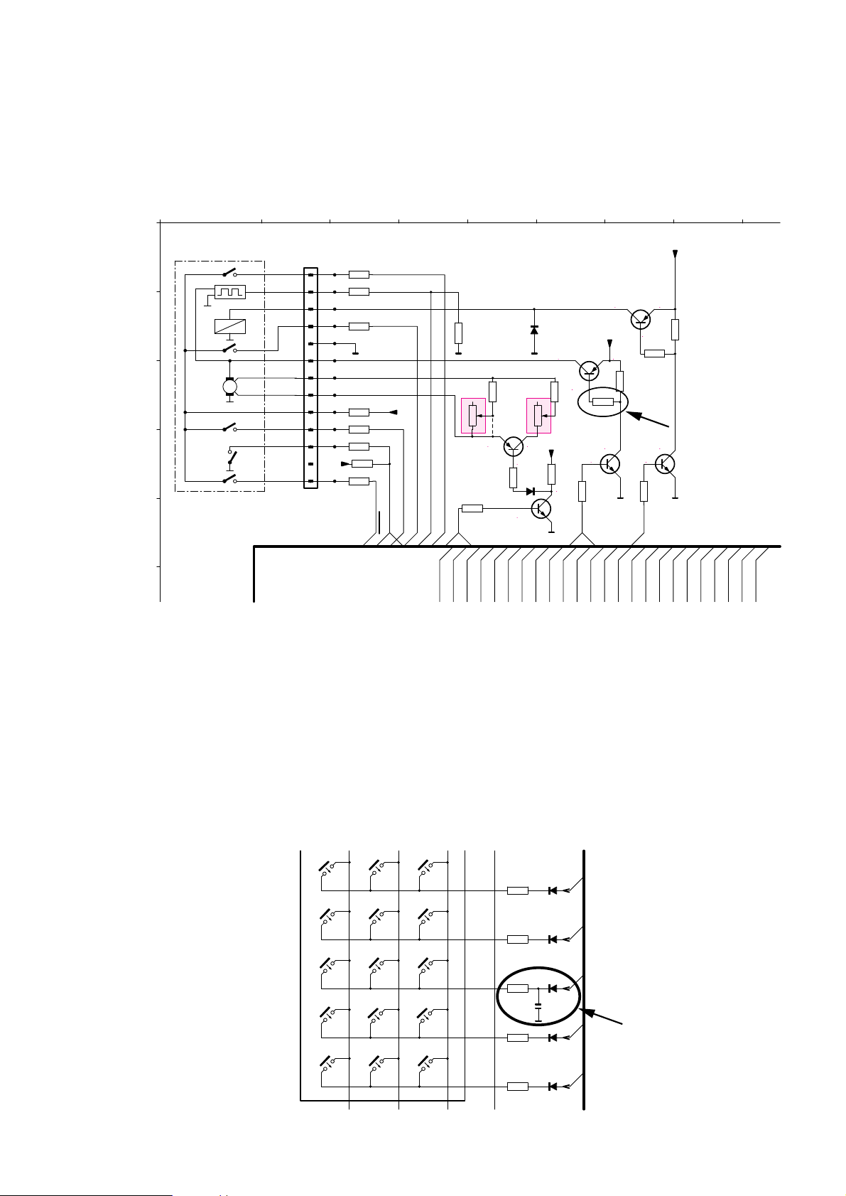
04.24 TYPENUMBER(S): FW610, FW620C, FW630, FW650C
SYMPTOM : Both cassettedecks are in-operative because the motor supply
transistor 7653 chip component (BC807/40) is out of order.
CURE : Change Resistor 3687 from 1kΩ to 470Ω.
In case the motor is blocked this modification gives a reduction of
VCE from approx. 1V to 0.5V, which halves the transistor load.
REMARKS : Transistor 7653 is a chip component (BC807/40).
Introduced from productionweek 9613 onwards.
04.25 TYPENUMBER(S): FW610, FW620C, FW630, FW650C
SYMPTOM : At high temperatures inside the set (>50°C) sometimes not used FTD
segments are blinking.
CURE : Add a capacitor of 220pF between cathode 6409 and ground.
This phenomenon is caused by long coppertracks.
REMARKS :
P15 P10 P09 P08 P07
4456
330E
4442
330E
4444
330E
4448
330E
4449
330E
6415
1N4148
6416
1N4148
6409
1N4148
6411
1N4148
6418
1N4148
1420
C2
1421
CLASS
1422
ROCK
1426
C3
1439
JAZZ
1440
DEMO
1441
C1
1442
DISP
1443
ANALY
1448
A3
1447
A2
1446
A1
1427
C4
1428
POP
1438
FLAT
CONTROL BOARD Chapter 6-2
220pF
High Speed
Normal Speed
CC
V
M
HALL
Tape Electronic
HALL-B
SOL-B
SOL-B
TAPE-A
INNERSWITCH
EJECT'
CRO2-B
TAPE-B
TAPE-B
SOL-A
2A2
SW1
SW2
SW3
CENTER-P-O
H-POS
HS
HS
B-REC-RVS
B-REC-RVS
B-REC-FWD
B-REC-FWD
2A1
MOTOR
MOTOR
MODE-B
MODE-B
2A0
3A0
3A1
3A2
1A1
1A0
Motor L
Motor H
REC.RVS
NC
CRO2-B
MODE-B
COMMON
VCC-B
GND
TAPE-B
SOL-B
EOT-B
REC.FWD
DECK - B
COMBI TAPE LOGIC / MUP PART
4 5 6 71 82 3
E
D
C
B
A
PP
P
PP
P
100k
3689
1k
3674
47k
3677
1k
3678
1k
3676
1k
3675
1k
3673
100k
3672
1k
3671
1k
3741
100k
3742
47k
3740
4k7
3685
5k6
3683
470R
3687
100k
3688
4k7
3680
47k
3686
4k7
3681
47k
3679
+uP
+uP
+MOTOR
+MOTOR
+MOTOR
7654
BC848C
7652
BC848C
7650
BC848C
T113
T114
T115
T116
T117
T118
T119
T120
T121
T122
T123
T124
6790
1N4002
6651
1N4148
9783
N
32
1
1
3684
10k
32
3682
10k
DD
7655
BC807-40
7651
BC858C
7653
BC807-40
1741
13
12
11
10
9
8
7
6
5
4
3
2
1
10,4V
0V
0V0V
11,1V 11,1V
11,0V
11,1V
11,1V
11,1V
6,2V 6,2V
5,5V
0V
0,7V
BG Audio Service Newsletter 1996 7/9
Page 52
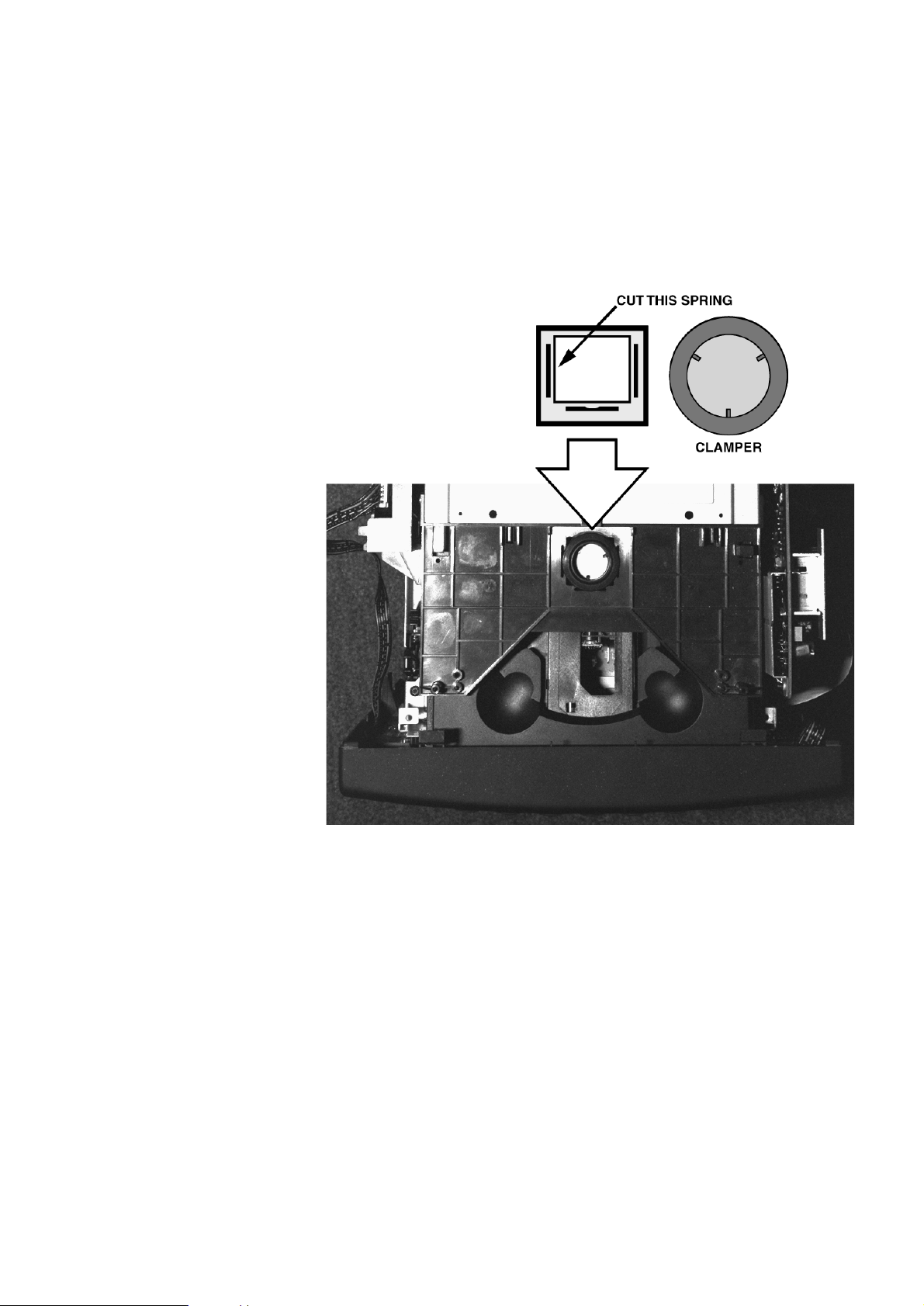
04.26 TYPENUMBER(S): FW650C
SYMPTOM : After transports - when the set is dropped down at the right hand
sidewall - sometimes the clamper is jammed.
Sometimes the clamper is pushed back when the CDM comes into
play-position, but it may also happen that the clamper jams
completely.
CURE : Cut the left hand plastic spring (see sketch below), then the CDM is
ALWAYS able to push the clamper back.
REMARKS :
BG Audio Service Newsletter 1996 8/9
Page 53

For internal use only PHILIPS
ISSUE 96.04 (96-04-18)
Published by:
Service Depar tment BG Audio SERVICE NEWSLETTER
04.27 TYPENUMBER(S): DCC730, DCC951, FW68
SYMPTOM : DCC head defect, no recording, several isolation shorts on DCC
head.
CURE : Isolation shorts are caused by ESD.To protect against ESD replace
(or bridge) C2999 on Read/Write panel with a 4,7kΩ resistor
(4822 051 20472). It is advised to introduce this in all mentioned sets
which will be offered for repair, and the modification has not been
implemented yet.
Implementation date: In R/W boards from production week 9540
onwards.
REMARKS :
DCC
BG Audio Service Newsletter 1996 9/9
Page 54

For internal use only PHILIPS
ISSUE 96.03 (96-03-07)
Published by:
Service Depar tment BG Audio
03.01 TYPENUMBER(S): AZ8055, AZ8056, AZ8057, AZ8262, AZ8267, AZ8289
SYMPTOM : The set give a whistling sound when playing a disc.
It sounds like mechanical oscillation.
CURE : Fault is caused by a peak in the gain response cur ve of the track
servo amplifier at about 15kHz.This is far above the bandwidth of
1.5kHz.This does not influence the behaviour of the track servo itself,
but causes mechanical noise produced by the pick-up.
The lay-out of combi board has been modified.
With the modified board C2859 and C2858 have been added and the
mechanical noise has been reduced by 5dB.
AZ8055, AZ8056, AZ8057:
Modified board is marked “.4” and has been introduced in week 9552.
AZ8262, AZ8267, AZ8289:
Modified board is marked “.5” and has been introduced in week 9601.
Service solution for sets without modified boards:
Add a capacitor of 2.7nF in parallel to R3826 (4822 126 12148).
SERVICE NEWSLETTER
BG Audio Service Newsletter 1996 1/8
Page 55
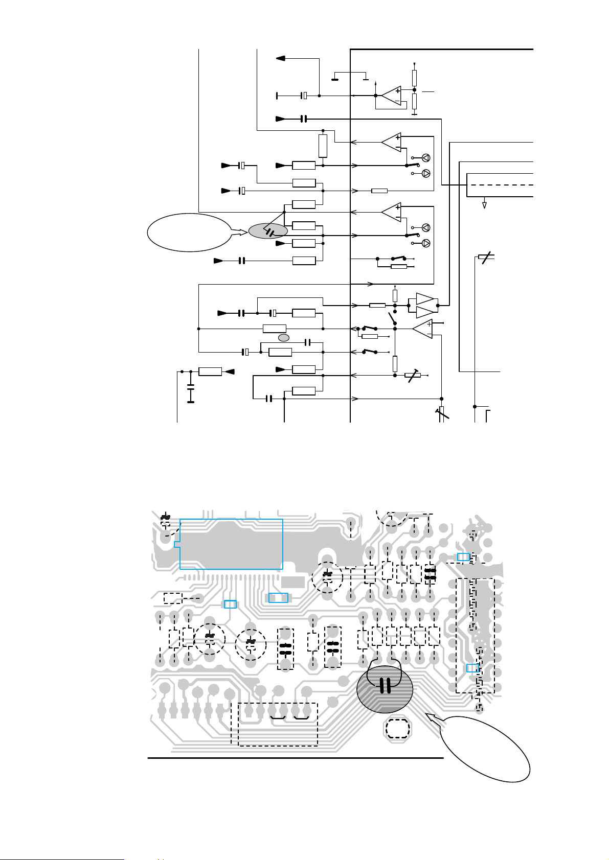
REMARKS :
TRACK
SLIDE
PW
PW
PW
REF
REF
REF
REF
REF
REF
REF
REF REF
+LASER
2859
2n7
100n
2815
2819
100n
2817
22n
100p
2814
2822
100n
3860
5k6
3856
33k
3k3
3857
3823
15k
3822
56k
3821
3k3
3820
82k
3824
150
3825
39k
3826
6k8
3827
5k6
3828
10k
3829
39k
T803
28181u
2820
0.22u
2821
2u2
2823
4u7
2816
0.22u
17
19
18
20
21
7
8
9
10
11
12
13
14
15
16
TEGain
OUT
OUT
TS
TRACK
DET.FILTER
Signal Generator
ADJUST LOGIC
TC/SHOCK
TS+
+
-
GND
BIAS
BIAS
SLIDE
SS-
SS+
TS-
TG2
A-B
TE-
TG1
TE
V
cc
V
cc
2
OUT
FOCUS/ALPC
7803
M62475FP
.5
Service solution
to reduce mech.
servo noise
2.1V
2.1V
2.1V
2.1V
2.1V
2.1V
2.1V
2.1V
2.1V
2.1V
2.1V
2.1V
2.1V
2.1V
3.4V
1
1
8
1
1
21
9840
9846
3854
1807
1810
2.7nF
3850
3851
3853
3856
3828
3829
3852
2835
3824
3825
3826
3827
2816
2818
2820
3860
3823
3820
3821
CONTROL/CD-PART – COPPERSIDE VIEW
GND DA
LASER
GND DA
1
1
FOCUS
TRACK
INNER
DISC
MOTOR
MOTOR
SWITCH
SLIDE
7806
1 16
1 16
98
Service solution
to reduce mech.
servo noise
1
42
3822
2822
21
22
7803
2856
2857
2819
2817
BG Audio Service Newsletter 1996 2/8
Page 56
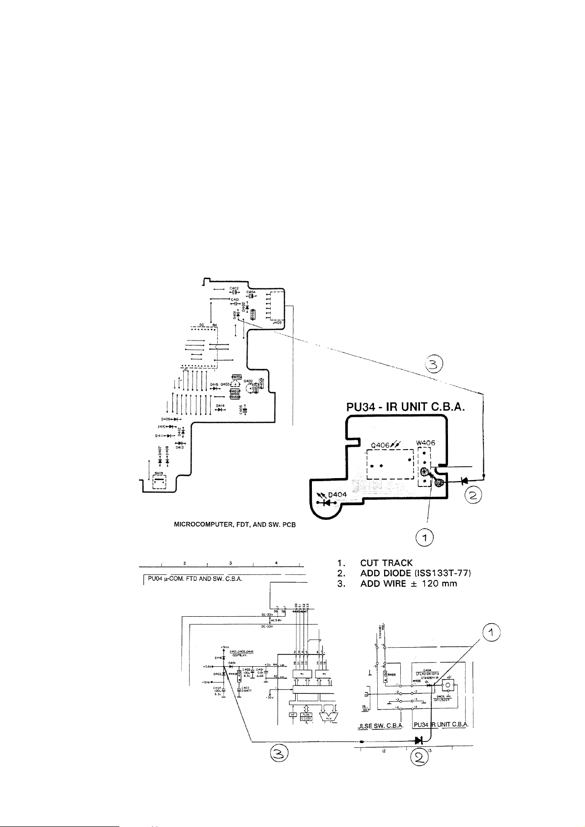
03.02 TYPENUMBER(S): FR951
SYMPTOM : Remote control does not activate the volume knob at temperatures
below 7°C.
CURE : Cause:
The supply voltage of the IR-eye is not clean, but has a ripple of
about 250mV peak-to-peak during IR reception.This ripple is caused
by the blinking standby LED dur ing IR reception due to a shared
supply line.
Cure:
The problem can be solved by isolating the supply line as follows:
1. Cut PC Board track between D404 and Q406
2. Add diode 1SS133T-77 (4822 130 33305)
3. Add wire (~120mm) between junction D401/D402 to D404 positive
Refering to next Figure. Part of schematic and layout drawing.
REMARKS :
BG Audio Service Newsletter 1996 3/8
Page 57

03.03 TYPENUMBER(S): FW14, FW15, FW36, FW56, FW350C, FW351C, FW360C, FW370G
SYMPTOM : The CD changer part is produces a scratching sound.
CURE : This can be solved by replacing the sub-chassis item 40,
service code: 4822 691 10477.
REMARKS :
03.04 TYPENUMBER(S): FW14, FW15, FW36, FW56, FW350C, FW351C, FW360C, FW370G
SYMPTOM : CD changer mechanism jammed and display shows “DEF”.
CURE : Cause:
1. CD clamped between the carr iage and the tray;
fault is normally not reproducible.
2. Disc can drop in when the tray is open.
Cure:
1. New software version 66 with improved timing of carriage
movement will prevent the CD from being clamped between
carriage and tray. Service code for µP is 4822 209 91162.
2. Rib on the r ight side of the tray will be removed.
Implemented from week 9546 onwards.
REMARKS : See also newsletter issue 96.01.11.
BG Audio Service Newsletter 1996 4/8
Page 58

For internal use only PHILIPS
ISSUE 96.03 (96-03-07)
Published by:
Service Depar tment BG Audio SERVICE NEWSLETTER
03.05 TYPENUMBER(S): DCC730, DCC951
INFORMATION : A demo mode have been defined in the software program:
Demo mode; Non protected:
After switching-on the power and with the set in STOP position, the
Demo mode can be entered by pressing the SCROLL button.
Pressing the STOP button will disable this mode.
Demo mode; protected (only for the trade):
When switching-on the power, while pressing the SCROLL button, the
protected trade mode will be entered. In this mode the drawer cannot
be opened.This mode can only be disabled by means of the O/C
button of the remote control (or by erasing the EEPROM in ser vice
mode).
REMARKS :
03.06 TYPENUMBER(S): DCC951
SYMPTOM : Wrong “COPY PROHIBIT” indication
CURE : Cause:
DCC951 display gives the indication “COPY PROHIBIT” when
recordings according to SCMS are made. Par ticular ly recordings from
SONY CD-players and MD-players (with pre-recorded software)
cause problems.
Cure: Replace digital microprocessor, item 7700 on digital board of
DCC module, by an OTP loaded with software programme D028
(service code 4822 209 12972).
REMARKS :
DCC
BG Audio Service Newsletter 1996 5/8
Page 59
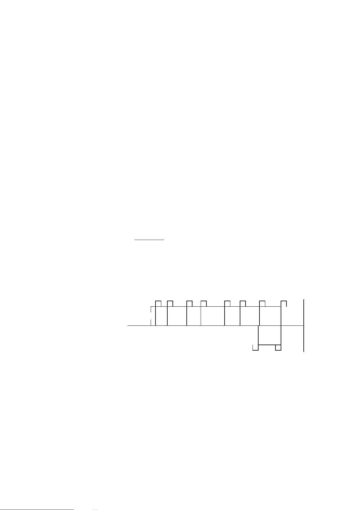
03.07 TYPENUMBER(S): DCC951
INFORMATION : USE OF EDIT MODE
When making a digital recording from CD player to DCC via CD
dubbing (controlled by ESI), EDIT can be selected by most of the
players e.g. CD931, CD940, CD911. CD951 (CD950) does not have
this feature and will always add 4 seconds AUTOSPACE in the CD
dubbing mode.
When EDIT mode has been entered, the CD player indicates the
tracks that will be recorded on side A and B depending on the
selected tape length.When recording on an Analogue recorder, the
recording will be made as indicated by the CD player.When on side
A, the last possible track has been recorded, the CD player will come
into the pause mode.The next track which will be recorded is
displayed.At the end of the tape, the recorder head (automatic
reverse), will switch to side B.The tape star ts r unning and after 6
seconds the recording will continue.
When recording digitally to DCC951, the way of recording is different.
1. CD911 (CD94 program)
The recorded CD of Peter Gabriel has 8 tracks with a total playing
time of 45'48".
In edit mode
the CD player selects tracks 1-7 on side A, track 8 on
side B.When track 7 has been recorded, the CD911 change over to
pause with track 8 selected.The DCC951 writes a “CONT. B” marker
on side A, the recorderhead will be reversed, and the recording will
continue with track 8.In comparison with a recording on an analogue
tape, a greater section of the tape will not be used.
CD911 (EDIT)
1
1
2 3 4 5 6 7 CONT B
END
OF
SIDE
A
B
LEAD IN
32 4 6 75
STOP
8
8
BG Audio Service Newsletter 1996 6/8
Page 60
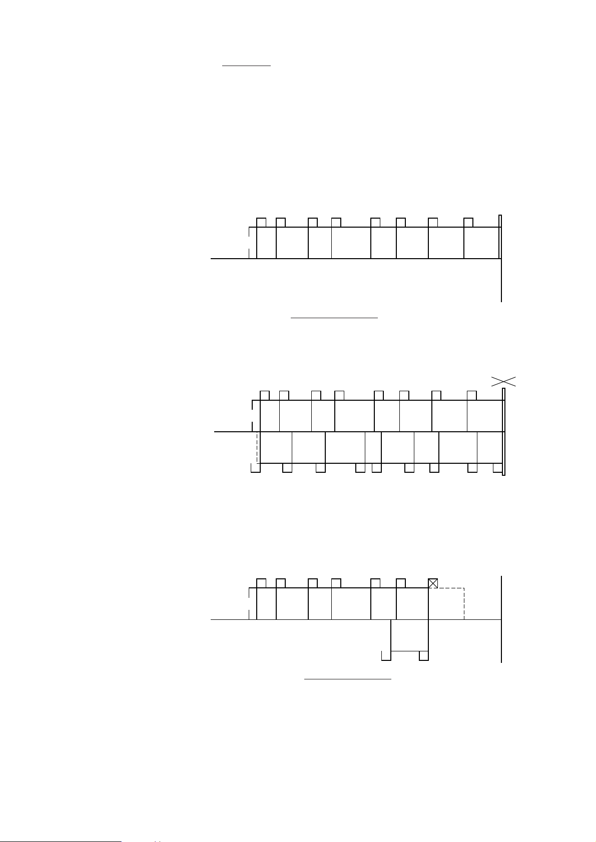
2. CD931(= CD930, CD93 program)
In edit mode, the CD player selects also tracks 1-7 on side A, track 8
on side B.When track 7 has been recorded, CD931 changes over to
pause with track 8 selected. DCC951 continues the recording till end
of side A.Then it rewinds to the last written marker, in this case
startmarker of track 7, overwrites this marker by a “CONT. B” marker
and continues recording of track 8 on side B, indicating recording
track 7.When playing back the recorded tape, track 7 of the CD will
not be audible, because it is marked by the “CONT. B” marker, forcing
the tape to continue on side B.
CD931 (NO EDIT)
When recording without edit mode
, all 8 tracks will be recorded on
side A, because the tape length (46') seems to be sufficient for this
CD.
CD931 (NO EDIT, NEXT RECORDING)
When making a next recording of the same CD via APPEND, DCC
starts the recording but when reaching the end of side A after 30",
DCC rewinds to the written start marker of track 9, replaces it by a
“CONT. B” marker, and recommences the recording of track 9 on
side B.
CD931 (EDIT)
Recording of a CD without edit mode
results in a better utilisation of
the tape, no tracks will be lost.
A peculiarity of DCC951 is that before the CD will be recorded a
second time completely, DCC displays: “TAPE FULL” although one
expects that enough space was left.This is caused by the procedure
of calculating the used tape length.
1
1
2 3 4 5 6 7
CONT B
END
OF
SIDE
A
B
STOP
LEAD IN
32 4 6 7
7
8
5
1
1
2 3 4 5 6 7
END
OF
SIDE
A
B
STOP
LEAD IN
32 4 6 7 85
8
CONT B
TAPE FULL
9
9
10
10111213141516
1113 12141516
1
1
2 3 4 5 6 7
END
OF
SIDE
A
B
STOP
LEAD IN
32 4 6 7 85
8
BG Audio Service Newsletter 1996 7/8
Page 61
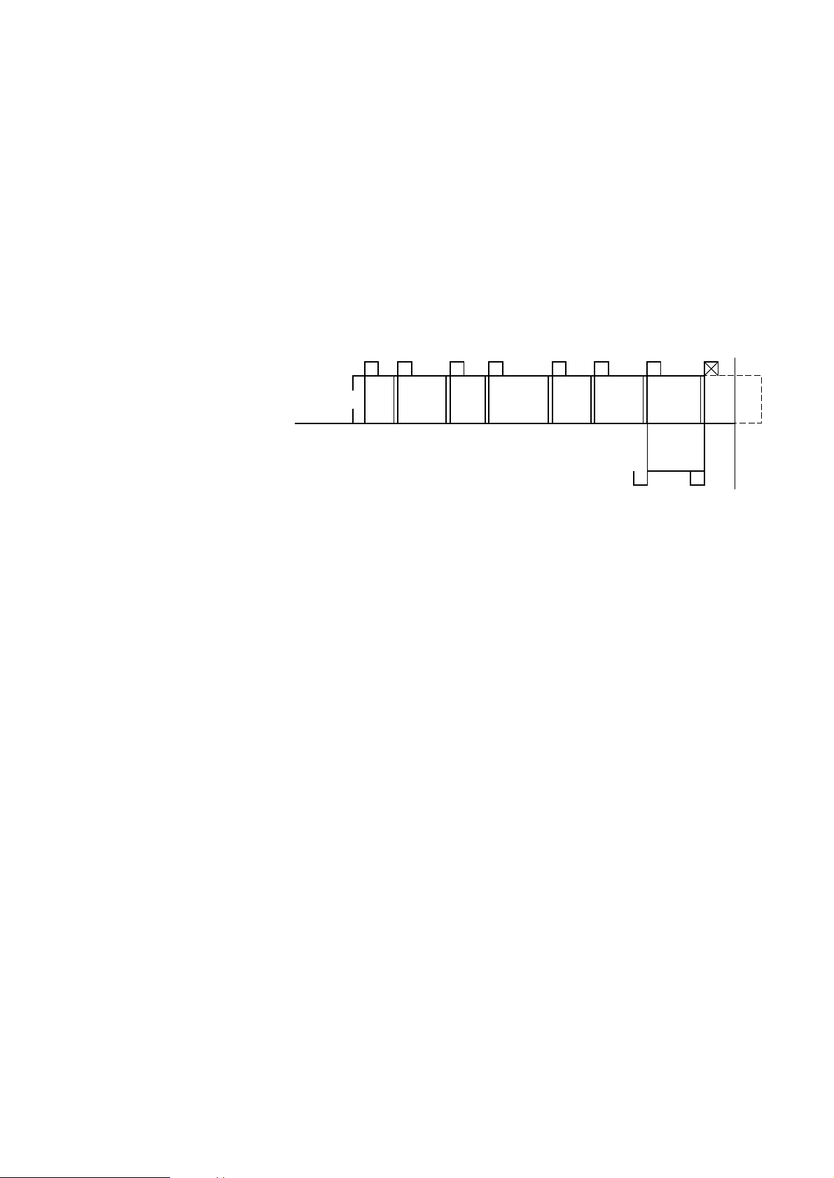
3. CD951(= CD950, CD93 program)
CD951 has no EDIT mode and in CD dubbing, an AUTOSPACE of 4
seconds will be added between the recorded tracks.This
AUTOSPACE cannot be switched off. Analogue recorders need this 4
seconds gap for the FAST TRACK ACCESS feature.
Before the recording of track 8 has been finished, the tape will reach
the end of side A . DCC rewinds to startmarker of track 8, replaces it
by a “CONT. B” marker and recommences the recording on side B.
No tracks will be lost.The disadvantage of the 4 seconds
AUTOSPACE is that when recording live recorded CDs, between
tracks an undesired pause will be audible. This can only be solved by
recording without CD Dubbing(CD SYNCHRO OFF).
CD951 (NO EDIT POSSIBLE, 4 SEC.AUTOSPACE)
CONCLUSION
EDIT mode has no use when recording digitally via CD Dubbing.
When recording via CD dubbing without EDIT, the DCC recorder
organises its own recording in an efficient way.Tracks interrupted by
the end of side, will be repeated on the next side. This interruption is
inaudible during play back.
Using EDIT mode might result in a loss of the last track on side A by
an inadequate software in the CD player (CD931), or in loss of tapespace (CD911).
The EDIT feature is only useful for analogue recordings.
1
1
2 3 4 5 6 8
CONT B
END
OF
SIDE
A
B
STOP
LEAD IN
32 4 6 8
8
8
5
7
7
BG Audio Service Newsletter 1996 8/8
Page 62

For internal use only PHILIPS
ISSUE 96.02 (96-02-05)
Published by:
Service Depar tment BG Audio
02.01 TYPENUMBER(S): AE2340
SYMPTOM : A selected preset frequency is replaced by another frequency.
CURE : In case presets are used to change stations, the frequency of the last
preset station may be lost, when waking up by Radio.
Temporarily an addendum sheet is packed by with the following
content:
Protecting preset stations when using the alarm RADIO mode.
Your selected stored frequencies (presets) may be lost as a result of
using the alarm RADIO mode. In order to safeguard your selected
presets, please follow the 3 steps below:
1. Set the desired alar m time.
2. Press the POWER ON/OFF button twice.
3. Now set the alar m switch to RADIO mode.
REMARKS : An Addendum sheet is added in the Instruction for Use of sets
produced from week 9606 onwards.
From April 1996 onwards, an updated Microprocessor IC will be
mounted.
This updated Microprocessor will safeguard the last preset frequency.
02.02 TYPENUMBER(S): AZ8006, ND6500, RD6050
INFORMATION : In Service Information A94-576 (4822 725 25358), the test points
were erroneously not given.
Please add on page 23 (circuit diagram) the location of test points as
described below:
TP1 = junction of RV103 and JP1
TP2 = pin 18 of U101
TP3 = junction of R111 and JP1
TP4 = pin 31 (RF) of U101
TP5 = pin 1 of U101
TP6 = junction of RV104 and JP2
REMARKS :
SERVICE NEWSLETTER
BG Audio Service Newsletter 1996 1/3
Page 63

–––––––––––––IMPORTANT–––––––IMPORTANT–––––––IMPORTANT–––––––––––––
02.03 TYPENUMBER(S): AZ9055
SYMPTOM : CD does not start-up or uses too long time to star t-up (8-10 sec.)
CURE : Fault is caused by the cross-talk between track and focus servo.
The problem can be corrected by the following actions:
1. Replace J112, where temporar ily a 1Ω resistor was mounted,
by a jumper wire.J112 can be found on CD Main Board
(layout diagram), near IC104 pin2. With this jumper pin2 of IC104
is connected to ground.
2. Change R106 from 39kΩ to 33kΩ (4822 050 23303).
One side of R106 is connected to IC101 pin72 (HF SUM).
3. Change C108 from 330pF to 220pF (5322 122 32346).
One side of C108 is connected to IC101 pin69 (BH).
After this modification: Check the E/F balance for a value within
range: 40mV ±20mV.
REMARKS : 1. This modification has been implemented in production from
week 9546 onwards.
2. CHANGING THE COMPLETE CD- DRIVE WILL NO
T
SOLVE THE PROBLEM SATISFACTORILY.
––––––––––––––––––––––––––––––––––––––––––––––––––––––––––––––––––––––––
02.04 TYPENUMBER(S): FW11
SYMPTOM : In the stand-by mode, noise from the loudspeaker box is audible.
CURE : The power supply switching circuit is defective, resulting in audio IC
TA8216H (IC501) is still working at standy mode.
Check: 1. Pin 55 of IC106 should be “low”.
2. Diode D116 (at CN302 pin 2) should be “low”.
3. Q501 should be “low”.
4. Pin 11 of IC501 should be “low”.
If either one is not “low”, the component concerned or the peripheral
is defective.
REMARKS :
02.05 TYPENUMBER(S): FW11
INFORMATION : During production, in order to improve shock sensitivity, two
suspension springs (item 243) at the rear side of CDM have been
changed.
New service code is 4822 404 21354. While 4822 492 71613 is
retained as the service code for the two suspension springs at the
front side.
REMARKS :
BG Audio Service Newsletter 1996 2/3
Page 64

02.06 TYPENUMBER(S): FW40, FW41
INFORMATION : For tape deck CWA409RR the ARM FR assy, item 22 on tape deck
exploded view, is available via service code 4822 403 71213 and
command gear wheel (cam gear), item 31 on tape deck exploded
view, is available via service code 4822 522 33524.
REMARKS :
02.07 TYPENUMBER(S): FW46, FW56, FW610, FW630
INFORMATION : For tape deck and CWA424RR the ARM FR assy, item 22 on tape
deck exploded view, is available via ser vice code 4822 403 71213.
REMARKS :
–––––––––––––IMPORTANT–––––––IMPORTANT–––––––IMPORTANT–––––––––––––
02.08 TYPENUMBER(S): MS6500, SM6050
SYMPTOM : CD does not start-up or uses too long time to star t-up (8-10 sec.)
CURE : Fault is caused by the cross-talk between track and focus servo.
The problem can be corrected by the following actions:
1. Replace J112, where temporar ily a 1Ω resistor was mounted,
by a jumper wire.J112 can be found on CD Main Board
(layout diagram), near IC104 pin2. With this jumper pin2 of IC104
is connected to ground.
2. Change R106 from 39kΩ to 33kΩ (4822 050 23303).
One side of R106 is connected to IC101 pin72 (HF SUM).
3. Change C108 from 330pF to 220pF (5322 122 32346).
One side of C108 is connected to IC101 pin69 (BH).
After this modification: Check the E/F balance for a value within
range: 40mV ±20mV.
REMARKS : 1. This modification has been implemented in production from
week 9546 onwards.
2. CHANGING THE COMPLETE CD- DRIVE WILL NO
T
SOLVE THE PROBLEM SATISFACTORILY.
––––––––––––––––––––––––––––––––––––––––––––––––––––––––––––––––––––––––
BG Audio Service Newsletter 1996 3/3
Page 65

For internal use only PHILIPS
ISSUE 96.01 (96-01-26)
Published by:
Service Depar tment BG Audio
01.01 TYPENUMBER(S) : General
INFORMATION : With this newsletter a modified issue numbering has been introduced.
From now on the year in which the newsletter is published, will be
added in front of the issue number and item number.
Example:
96.01.03 = itemnumber 3 of issue number 1 published in 1996.
REMARKS :
01.02 TYPENUMBER(S): AQ6548, AQ6549
SYMPTOM : No headphone output or headphone output signal is intermittent.
CURE : Fault is caused by a cracked copper-track at the headphone socket.
Check copper-track and re-connect the broken track with jumpers.
REMARKS : Following modification had been implemented:
Main Cabinet tool from week 9516 onwards
Rear Cabinet tool from week 9531 onwards
Printed Circuit Board Copper-track from week 9538 onwards
01.03 TYPENUMBER(S): AQ6548, AQ6549
SYMPTOM : A squeaking sound is audible.
CURE : Pin 1 of IC LAG673 has loose contact due to the pressure from the
rear cabinet. Check and touch up the solder connection at
IC LAG673.
REMARKS : From week 9522 onwards, rear cabinet has been modified to avoid
pressing the IC.
SERVICE NEWSLETTER
BG Audio Service Newsletter 1996 1/6
Page 66

01.04 TYPENUMBER(S): AZ8050, AZ8051, AZ8052, AZ8150, AZ8055, AZ8056, AZ8057,
AZ8262, AZ8267
INFORMATION : Service Manual
correction EXPLODED VIEW / drawing 1 page 8-1:
Description and position numbers 448 (knob slide MODE) and 449
(knob slide BAND) are interchanged in the Exploded View/drawing 1
of the service manuals.
The drawn position of item number 448 should read Knob slide Band
and item number 449 should read knob slide MODE.
In the partslist ser vice code numbers and descriptions are correct.
Ordering 4822 411 61999 will deliver knob slide "MODE"
Ordering 4822 411 62001 or 4822 411 62003 will deliver the desired
knob slide "BAND"
REMARKS :
01.05 TYPENUMBER(S): AZ8051
INFORMATION : For Region Hongkong the new version AZ8051/11H will be
introduced.
For further repair information see Service Manual AZ8050, AZ8051,
AZ8052, AZ8150 (4822 725 24954).
Difference to AZ8051/01: mains cord 4822 321 10886
REMARKS :
01.06 TYPENUMBER(S): AZ8340, AZ8345, AZ8350, AZ8357, AZ856
INFORMATION : Service Manual, Addition to specifications
Microphone input impedance: approximately 2.5kΩ
Microphone input sensitivity: 0.1mV
REMARKS :
01.07 TYPENUMBER(S): AZ9350, AZ9450, AZ9555
INFORMATION : Service Manual Addition to specifications Microphone input
impedance: approximately 10kΩ.Applied microphones may have
output impedance of 30 till 600Ω.
REMARKS :
01.08 TYPENUMBER(S): AZ9350, AZ9355, AZ9555
SYMPTOM : CD shows “Door open” or CD loaded but does not function.
CURE : The problem is due to heavy oxidation of the leaf switch 1920 causing
poor contact (permanent or intermittent).
REMARKS : Switch of improved quality has been applied and the mechanical door
activation has been re-designed. Both improvements have been
implemented from week 9529 onwards.
BG Audio Service Newsletter 1996 2/6
Page 67
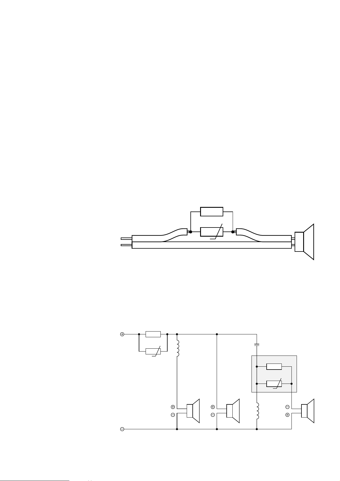
01.09 TYPENUMBER(S): CD400, CD410, FR400, FR410, FS400, FS410
INFORMATION : WARNING:DO NOT CONNECT CD400 WITH FR410!!!
The CD400 (from system FS400) looks identical to CD410 (from
system FS410). Even the cable to connect the CD-set to the receiver
is the same.
If only the set CD400 is brought-in for repair this set should NOT be
connected to the FR410.
USE ONLY CD400 TOGETHER WITH FR400
USE ONLY CD410 TOGETHER WITH FR410.
The voltages for CD410 and CD400 are not identical.
Fuses might be blown after that connection!!
REMARKS :
01.10 TYPENUMBER(S): FB695, FB696
INFORMATION : Service hints:
For loudspeakerbox produced before week 9545 and brought in for
repair of a defective tweeter AD11401/T6 (4822 240 70223), it is
necessary to add a tweeter protection circuit in the wire to the
tweeter.
See next drawings or ser vice information A95-101 (4822 725 24783).
The extra components used are:
R = resistor 5.6Ω 5Watt (4822 053 32568)
PTC = PTC RXE040 (4822 116 40264)
In boxes produced from week 9545 and onwards, this protection
circuit has already been implemented.
From week 9606 onwards the protection circuit has been integrated
on the filter unit (4822 214 51297).
woofer bottom
PTC
5002
3101
PTC
3102
5001
2001
woofer up tweeter
Tweeter
Protection
3002
3001
Brown
Black
Input
PTC
R
tweeter
BG Audio Service Newsletter 1996 3/6
Page 68

item service code descr iption
––––––––––––––––––––––––––––––––––––––––––––––––––
5001 4822 157 62595 air coil 330µH
5002 4822 157 62596 ferrite coil 820µH
2001 4822 124 21436 bipolar capacitor 4.7µF 100VDC
3001 4822 116 82638 resistor 5.6Ω 25Watt
3002 4822 053 32568 resistor 5.6Ω 5Watt
3101 4822 116 40201 PTC RXE135
3102 4822 116 40264 PTC RXE040
REMARKS : This modification should be applied in each box FB695 and FB696
offered for repair.
This publication will be followed by Service Information A95-101.
01.11 TYPENUMBER(S): FW14, FW15, FW36, FW54, FW56, FW350C, FW351C, FW360C
INFORMATION : The microprocessor of the CDC Module is changed to
4822 209 91162 (software version 66) with printing mark
“CDC51050”.
Included in this new software are:
a) During Standby mode the cam gear will go into stocker mode
making it safer for transpor tation and drop-test.
b) Improve disc detection to prevent the top disc from dropping into
mechanism if 2 discs have been loaded.
REMARKS : Implemented in production from week 9550 onwards.
01.12 TYPENUMBER(S): FW36, FW351
SYMPTOM : In stand-by mode: LCD display shortly lights-up or CDC-unit makes
noise.
CURE : When the unit is in Stand-by mode the units LCD display may flash
On and then Off momentarily. The unit may also initialize the CDC
Mechanism.The customer may complain that his unit is making noise
when the unit is not being used.
This symptom is caused by:
AC (mains) voltage which might drop about 10 to 15 volts for about
30ms to 70ms.
This voltage drop is detected as a Powerdown (or AC interruption).
The CDC Mechanism is then initialized and returns into Stand-by
mode.
The Powerdown circuit is too sensitive to AC voltage drops.
The AC voltage drop may be caused by e.g. the Central Heat and Air
installation in the home turning on.
The symptom can be solved by:
Add a 10kΩ resistor 5%, 0.5W (ser vice number 4822 116 52233)
between ground and AC connection AC2.
This component has to be added on the Combi Board.
(Mount resistor 10kΩ on printed board side between jumping wire
9318 and connector 17, pin 3 & 4).This solution has been applied
and drawn in service manual FW360: resistor 3253.
REMARKS :
BG Audio Service Newsletter 1996 4/6
Page 69

01.13 TYPENUMBER(S): FW46, FW56, FW610, FW620C, FW630, FW650C
INFORMATION : Partslist:
The complete (DOUBLE) tape deck mechanism (A1 + A2) is available
via 4822 691 20928.
REMARKS :
01.14 TYPENUMBER(S): FW68
INFORMATION : Complete loudspeakerboxes are available as spareparts:
Left box 4822 445 10493
Right box 4822 445 10494
REMARKS :
01.15 TYPENUMBER(S): FW330, FW331G, FW360, FW370C
INFORMATION : Alarm or Wake-up volume problem
The wake-up volume is designed such that the buzzer is independent
on the volume level. If CD or Tuner is selected the wake-up volume
will start from volume 01 and gradually increases to a maximum
volume 15 (3 bar on the display) after 1 min and 45 sec.
During this period if any buttons/knobs is activated, this gradual
volume increase process will stop permanently even before the
maximum volume 15 is reached.This may create an impression that
the alarm or wake-up volume is not working if the customer turns the
volume knob to check why there is no alar m sound.
REMARKS :
BG Audio Service Newsletter 1996 5/6
Page 70

01.16 TYPENUMBER(S): FW610, FW620C
SYMPTOM : No sound
CURE : It has been found in showrooms where sets of FW610 and FW620C
are shown together with FW630 and FW650C, the INCREDIBLE
SOUND command from a FW630 or FW650C Remote control also
activates the FW610 and FW620C.However than there remains no
output signal.
The “incredible sound” remote control command causes the IC7553
(TEA6321) to switch from FRONT to REAR output.
See also Service manual block diagram on page 9-4.
Due to the fact that the FW610 and FW620C sets have not
implemented the Incredible Sound feature no sound is audible at the
speaker any more.
To make the set playing again one can choose out of two possibilities:
1) Press the INCREDIBLE Sound button on the FW650C or FW630
Remote Control again.
This causes the set to switch to normal Stereo again.
2) Use the EEPROM CLEAR Test as shown in the Ser vice Test
Program (Page 3-5).
This command will load the default data in the EEPROM.
A modification of the set is under investigation.
WARNING
DO NOT SHORT-CIRCUIT THE FRONT TO THE REAR OUTPUT OF
IC 7553.This will damage the IC.
REMARKS : This publication will be followed by a service information.
01.17 TYPENUMBER(S): ST2010, ST4010,TS2100,TS4100
SYMPTOM : The record player does not move.
CURE : The ON/OFF switch assembly on the record player has to be
replaced due to broken holder and oxidized contacts.
The switch is known as “SW8” in the schematic for Tuner/EQ and it is
available via ser vice code 4822 277 11503.
REMARKS : From week 9537 onwards, the tooling of the plastic holder of the
switch assembly had been modified. Also the surface of the contact
plate is provided with a nickel plated finishing.
BG Audio Service Newsletter 1996 6/6
 Loading...