

Page 1

For internal use only PHILIPS
ISSUE SNL2001.02 (01-05-16)
Published by:
Service Depar tment Audio
BUSINESS CREATION UNIT AUDIO
02.01 TYPENUMBER(S): ACT7585
INFORMATION : Correction to Service Manual
CD-drive DA23LN (3103 309 05320) has been used instead of
DA23L (3103 309 05340). The new CD-drive requires the following
modification for proper detection of the drive version:
Add 3418 4822 051 30008 Chip Jumper 0603
Delete 3419
REMARKS :
02.02 TYPENUMBER(S): ACT7585
INFORMATION : Correction to the Service Manual, Partslist
Resistor 3869 should be 47Ω (4822 051 30479).
REMARKS :
02.03 TYPENUMBER(S): AZ1018
INFORMATION : In course of production, resistor 3452 has been changed from 2.7kΩ
to 4.7kΩ (4822 051 30472) to improve “LCD leakage”.
REMARKS :
02.04 TYPENUMBER(S): AZ1110, AZ1111, AZ1112, AZ1113, AZ1114, AZ1116, AZ1117,
AZ1118, AZ1119, AZ8084, AZ8085, AZ8086, AZ8087
SYMPTOM :
Set doesn’t work with some specific batteries due to inproper battery
contact.
CURE : The guiding rib in the battery compar tment has been modified.
REMARKS : Modified parts are used in production with production code
KZ010049136XXX from week 0049 onwards.
X112IRIS CODE
SERVICE NEWSLETTER
Service Newsletter 2001 – BCU Audio 1/6
Page 2

02.05 TYPENUMBER(S): AZ2020, AZ2025
INFORMATION : Correction to Service Manual, Mechanical Partslist
The codenumber of the Contact Plate (item 449) should read
3140 111 21320.
REMARKS :
02.06 TYPENUMBER(S): AZ2785
INFORMATION : Correction to Service Manual, Mechanical Partslist
Items 443 (Cass Keys A) and 444 (Cass Keys B) will be delivered
together as a service kit. The codenumber reads 9965 000 09156.
REMARKS :
02.07 TYPENUMBER(S): CD6660
INFORMATION : Correction to Service Manual, Wiring Diagram and Electrical Partslist
The item number of the Flexible Foil 8800 is incorrect. It should read
8000 4822 320 12178 Flexible Foil
REMARKS :
02.08 TYPENUMBER(S): CDR570, CDR600, CDR602, CDR770, CDR771, CDR775, CDR776,
CDR778, CDR785, CDR786, CDR930, CDR950, CDR951, FW-R7,
FW-R8, FW-R88
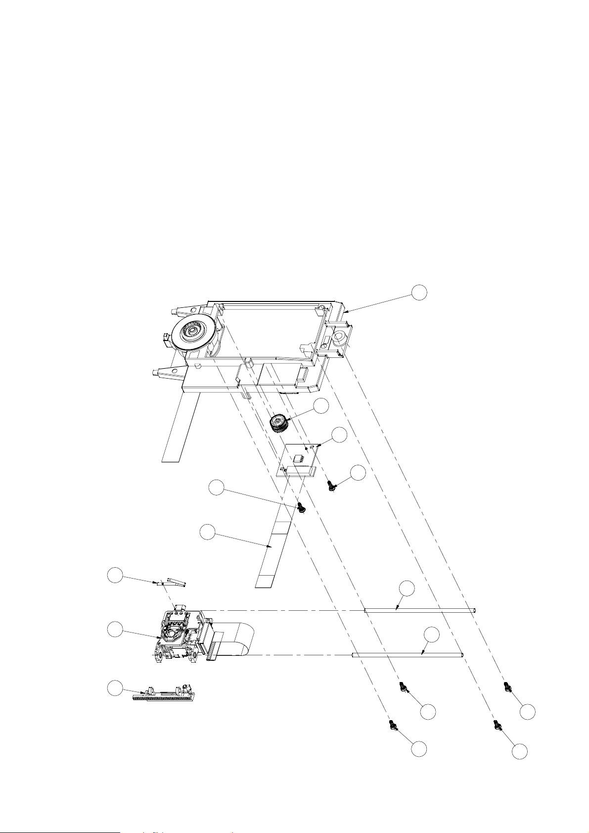
INFORMATION : In case the Optical Pickup Unit “OPU” (item 2) has to be replaced, it
is absolutely necessary to replace the axle (item 4) at the same
time. For reference see Exploded View CDM3800 on next page resp.
chapter 4.4 of 2nd line Service Manual CDR570,... 3104 125 40110.
Also gear rack (item #) has to be investigated for damages of its
teeth. As follows the instr uction how to replace these parts.
1. Demounting
1.1. First demount loader CDL4009 and CDR-MainBoard as given in
Mechanical Instructions, chapter 4.1.
1.2. Now the OPU can be de-mounted.See chapter 4.4 (Exploded
View CDM3800)
1.3. Loosen 2 screws (6 and 8)
1.4.Take away the old OPU 2 with its axle 4 and gear rack assy #
by lifting it up at that released side and then shift it from it's other
axle 3.
1.5.Take care of spring ™. It can be reused for the new OPU.
1.6. Remove gear rack # from the OPU by removing axle 4. If the
gear rack is not damaged it can be reused for the new OPU.
2. Mounting
2.1. Mount the new axle 4 through new OPU and gear rack #
2.2. Mount spr ing ™
2.3. Position the OPU under axle 3.Take care of spring ™.
2.4. Press the gear rack # in such a way that both rackteeth are in
line with each other.Interlock gear rack # with gear wheel @.
Service Newsletter 2001 – BCU Audio 2/6
Page 3
The tension on the gear-rack will reduce the offset of the
mechanical movement drastically.
2.5. Fasten axle 4 with 2 screws (6 and 8)
2.6. Now the OPU is mounted in the CDM. Write down the
parameters of the OPU for later adjustments.The parameters
represent the last five digits of the 12 NC, the 0.7mW value and
the 20mW value (i.e.13981;00735;02098).
2.7. Remount and reconnect the CDR-main-board and do not forget
to execute the adjustment procedure via ComPair in order to
match the CDR-main-board with the new OPU.
3. Adjustment
3.1. After replacement of the OPU it is absolutely necessar y to star t
ComPair Adjustment procedure immediately. Follow the
instructions as given by ComPair.
REMARKS :
EXPLODED VIEW CDM3800
12
1
23
26
24
3
4
7
8
6
5
22
2
13
25
Service Newsletter 2001 – BCU Audio 3/6
Page 4

02.09 TYPENUMBER(S): ECO5, ECO6 T uner Board
SYMPTOM :
After a few minutes of operation there is no sound audible although
the display shows still the correct tuning frequency.
When the tuner is switched off for some time the displayed frequency
will be completely wrong after switching on again.
CURE : The most probable reason is a leaky ceramic capacitor 2165
(resistance of a few hundred Ohm can be measured).
The defective capacitor causes a drop of Vref (1.5V instead of 2V at
pin 1 of IC7101) along with a drop of the internal stabilized voltages
VstabA and VstabB (0.8V instead of 1.4V at pins 34 and 38).
As a result IC7101 will not work anymore.
The problem can be solved by replacing capacitor 2165.
REMARKS : Check also ceramic capacitors 2139 and 2152.
02.10 TYPENUMBER(S): FW-R7, FW-R8, FW-R88
INFORMATION : Correction to the Service Manual, Mechanical Partslist chapter 12-3
The codenumber for Rubber Foot pos. 271 should read
3104 217 72032.
REMARKS :
02.11 TYPENUMBER(S): FW-V220, FW-V320
INFORMATION : Correction to the Service Manual, Circuit diagram and Partslist
Combi Board
2405 Deleted
3456 Deleted
3681 4822 116 52276 3.3kΩ 5% 0,5W
3682 4822 116 52276 3.3kΩ 5% 0,5W
REMARKS :
02.12 TYPENUMBER(S): MC-10, MC118
SYMPTOM :
Sharp voice is audible on recording.
CURE : Change resistor 3732 from 10Ω to 15Ω (4822 116 82182).
REMARKS : Modification has been implemented in production from week 0101
onwards.
2451IRIS CODE
0123IRIS CODE
Service Newsletter 2001 – BCU Audio 4/6
Page 5
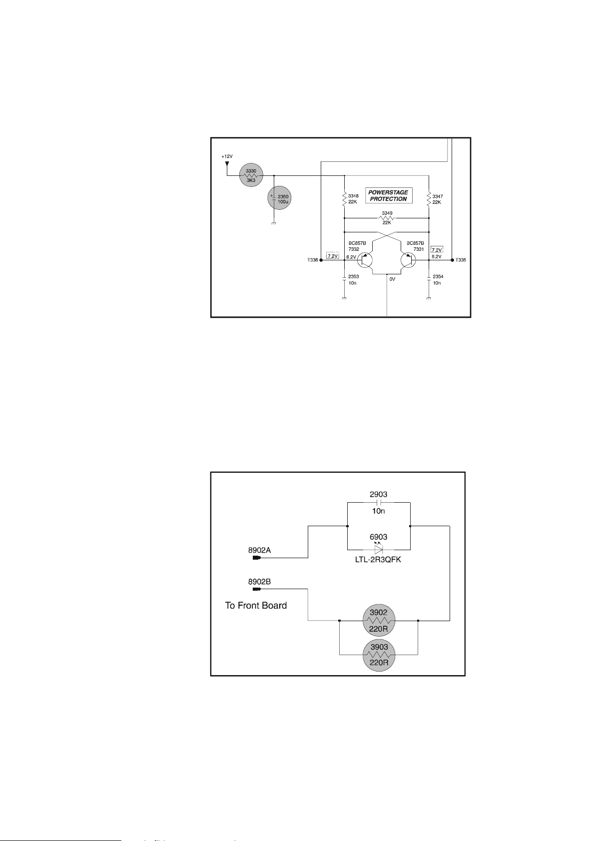
02.13 TYPENUMBER(S): MC-10, MC-20, MC-30, MC118, MC148
INFORMATION : In course of production, the following components have been added
on the Combi Board to improve power muting:
2350 4822 124 40207 100µF
3330 4822 116 52269 3.3kΩ
REMARKS :
02.14 TYPENUMBER(S): MC-30
INFORMATION : Backlight board: In course of production, resistor 3903 has been
added in parallel to resistor 3902 to prevent overheating.
The value for both resistors is 220Ω, available with codenumber
4822 117 11503.
REMARKS :
Service Newsletter 2001 – BCU Audio 5/6
Page 6

02.15 TYPENUMBER(S): MC-30/37
INFORMATION : Correction to Service Manual, Mechanical Partslist
The codenumber of the Mains Cord Relief for /37 (item 439) should
read 3140 113 22100.
REMARKS :
02.16 TYPENUMBER(S): MC-45, MC-50
INFORMATION : Correction to the Service Manual, Circuit diagram and Partslist
Front Control Board
6300 4822 130 11589 LTL-1CHAE
6301 4822 130 11589 LTL-1CHAE
6302 4822 130 11589 LTL-1CHAE
6303 4822 130 11589 LTL-1CHAE
6400 9322 167 73676 LTL-4221NLC-KA
REMARKS :
02.17 TYPENUMBER(S): MC-70
INFORMATION : Correction to the Service Manual, Circuit diagram and Partslist
Front Control Board
6400 9322 167 73676 LTL-4221NLC-KA
Front Display Board
3201 4822 052 10228 2.2Ω 5% 0,33W
3202 4822 052 10228 2.2Ω 5% 0,33W
Mechanical & Accessories – Main Unit
141 3139 113 27010 Cut Sheet Display Blue
1131 3139 110 35560 Flex Cable 19pin 18cm AD folded
1133 3139 110 35570 Flex Cable 9pin 10cm AD
1138 3139 110 35520 Flex Cable 19pin 10cm AD
REMARKS :
02.18 TYPENUMBER(S): MC118, MC148
INFORMATION : It might happen that sets are returned with broken CD Door (item
442) and CD Tray (item 434). The broken area is around the holder
for CD Door Spring. From production week 0112 onwards the parts
have been strengthened by increasing the wall thickness of the spring
holder and adding supporting ribs.
REMARKS : Modified parts are used in production from week 0112 onwards.
Service Newsletter 2001 – BCU Audio 6/6
 Loading...