

Page 1

Page 2

EN
Contents
33 SSaaffeettyy IInnssttrruuccttiioonnss
33 PPrroodduucctt DDeessccrriippttiioonn
44 OOppeerraattiioonn aanndd IInnssttrruuccttiioonnss
77 WWaarrrraannttyy
77 TTeecchhnniiccaall SSuuppppoorrtt
2
Page 3

Safety Instructions
IIMMPPOORRTTAANNTT
RREEAADD
EN
WARNING INSTALLATION OF THIS PRODUCT NEAR POWER LINES
IS DANGEROUS. FOR YOUR SAFETY, KEEP LADDER AND ANTENNA
AWAY FROM POWER LINES. CONTACT MAY CAUSE ELECTROCUTION.
BBEEFFOORREE
IINNSSTTAALLLLAATTIIOONN
Antenna Grounding and Safety Warning
1. Outdoor antennas and lead-in conductors from antenna to a building, should
not cross over open conductors of electric light of power circuits.They should
be kept away from all circuits to avoid the possibility of accidental contact.
2. Each conductor of a lead-in from an outdoor antenna should be connected
with an antenna discharge unit. Antenna discharge units (or Lightning
Arrestors) should be located outside the building or inside the building
between the point of entrance of the lead-in and the TV, and as near as practical to the entrance of the conductors to the building.
Product Description
The rotator is designed to turn and accurately position even large antennas,
allowing best possible reception. Rotation of the rotator unit is synchronized
with commands from the indoor control unit to automatically go to up to 12 different memorized positions or any direction chosen manually.The connecting
cable between the control unit and the rotator unit carries only safe, low voltage power.When the operating command sequence is finished, the unit shuts off
automatically and draws no current until activated by a remote or manual command to the control unit.
3
Page 4
EN
Operation and Installation
Operating and Installation Instructions
TTIIP
P
– While you are still on the ground and before mounting the rotator unit to
the support mast, temporarily connect the rotator unit to the control unit with
the control cable and perform the alignment (and basic system check) by following Steps 2 and 5 and 8 below.
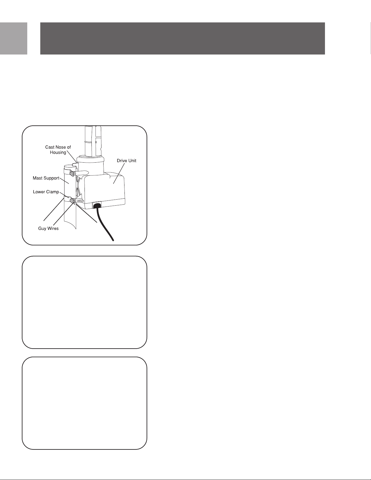
Fig. 1
Fig.
Step 1 - Rotator Unit Mounting
If not mounting the rotator unit inside a tower, attach the the rotator unit to
the support mast by loosening the nuts enough to slide the clamps over the
mast. Lower the rotator unit until the cast nose of the drive housing sits on top
of the suppor
7/16” wrench will cause the teeth of the clamp to grip the mast securely. DO
NOT over-tighten to the point that you deform the mast, as this will reduce its
strength.
Mast Diameters of 1 1/4” to 2” (3-5cm) may be used.The 1 1/2” (3.8 cm) size
or larger is recommended for un-guyed mast over 6’ long or where large antennas are used. If guy wires are used, fasten two through each of the two holes of
the lower clamp.
t mast and tighten the nuts. Moderate tightening of the nuts with a
Step 2 - Rotator Unit (Rotator) Connection
Up to 280’ of 20 AWG 3 conductor cable may be used. For longer runs use heavier gauge wire.To attach cable to rotator unit, open the bottom cover using a
screwdriver. Remove the grommet and insert the cable through the slot. Press
the grommet back into the slot. Separate leads 1 1/4” and strip off 1/2” insulation. Find the silver (or wide jacketed lead) and connect it to terminal 1. Connect
the adjacent lead to terminal 2 and the next lead to terminal 3. If 4 wire cable is
used connect both wire 3 and 4 to terminal 3. Make sure there are no loose
strands which can short between terminals. Recheck the wiring order and then
ely close the bottom cover. To avoid moisture collecting in the cable, be
secur
2
sure the jacket passes through the grommet.
4
Fig. 3
Step 3 - Antenna Mast
Antennas should be mounted as close as possible to the r
1-1/4” – 1-1/2” mast to a length not exceeding that shown in the chart below
and mount the antenna at the top of the mast.
line to antenna.
• Small - Up to 5’ (1.5M) Long 5’ (1.5M)
• Medium - Up to 8’ (2.4M) Long
• Large - Over to 8’ (2.4M) Long 2’ (0.6M)
• Large with braces See Note
wo antennas* 4’ (1.2M)
T
•
3’ (0.9M)
Be sure to attach transmission
otator unit.
Cut
Page 5

Page 6

Page 7

Warranty
MEMORY CHANNEL(S) (DEGREES)
D
IRECTION
A
B
C
D
E
F
G
H
I
J
K
L
Limited One-Year Warranty
Philips warrants that this product shall be free from defects in material, workmanship and assembly, under normal use, in accordance with the specifications
and warnings, for one year from the date of your purchase of this product.This
warranty extends only to the original purchaser of the product, and is not transferable.To exercise your rights under this warranty, you must provide proof of
purchase in the form of an original sales receipt that shows the product name
and the date of purchase. For customer support or to obtain warranty service,
please call 919-573-7863. THERE ARE NO OTHER EXPRESS OR IMPLIED
WARRANTIES. Philips’ liability is limited to repair or, at its sole option, replacement of the product. Incidental, special and consequential damages are disclaimed where permitted by law. This warranty gives you specific legal rights. You
may also have other rights that vary from state to state.
EN
Technical Support
Technical Support
For technical support send an email with the model number of the product and
a detailed description of your problem to:
Email: accessorysupport@philips.com
©2006
Accessories Ser
Philips
Accessories and Computer Peripherals,
Ledgewood, NJ 07852 USA
Manufactured in China
Printed in China
vice Center
7
Page 8

SP
Contenido
9 Instrucciones de seguridad
9 Descripción del producto
10 Instalación y operación
14 Garantía limitada por un año
14 Asistencia Técnica
8
Page 9

Instrucciones de seguridad
A ADVERTENCIA LA INSTALACION DE ESTE PRODUCTO CERCA DE
L
LINEAS DE FUERZA ES PELIGROSA. PARA SU SEGURIDAD, MANTENGA ESCALERA Y ANTENA LEJOS DE LINEAS DE FUERZA. LA ELECTROCUCION DE LA CAUSA DEL MAYO DEL CONTACTO.
Puesta a tierra de la antena y advertencia de
IMPORTANTE
LEER ANTES DE
INSTALAR
seguridad
11..
Las antenas de exterior y los conductores que ingresan a un edificio desde
la antena no deberían cruzarse con conductores abiertos de iluminación o
circuitos de energía eléctrica.Deberían mantenerse alejados de todos los circuitos para evitar la posibilidad de un contacto accidental.
22
. Cada conductor de un cable de entrada desde una antena de exterior
debería conectarse a una unidad de descarga de antena. Las unidades de
descarga de antena (o supresores de sobretensiones de origen atmosférico)
deberían estar ubicados fuera del edificio o,dentro del edificio,entre el punto
de ingreso del cable de entrada y el televisor, y tan cerca como sea posible
de la entrada de los conductores al edificio.
SP
Descripción del producto
El rotor fue diseñado para girar y posicionar en forma precisa incluso antenas
grandes, permitiendo la mejor recepción posible. La rotación de la unidad de
rotor está sincronizada con los comandos de la unidad de control interior para
posicionarse en 12 puntos guardados en memoria, o en cualquier posición seleccionada en forma manual. El cable de conexión entre la unidad de control y la
unidad de rotor solamente transporta corriente segura de bajo voltaje. Cuando
se finaliza la secuencia de comandos de operación, la unidad se apaga automáticamente y no transmite corriente hasta que se active desde el control remoto
o a través del comando manual de la unidad de control.
9
Page 10

SP
Instalación y operación
Fig. 1
Fig. 2
Instrucciones de instalación y operación
CONSEJO: Mientras que aún se encuentre en el piso y antes de montar la unidad
de rotor en el mástil de soporte, conecte temporalmente la unidad de rotor a la
unidad de control con el cable de control y realice la alineación (y la verificación
del sistema básico) siguiendo los pasos 2, 5 y 8 que se indican debajo.
PASO 1 – Montaje de la unidad de rotor
Si no monta la unidad de rotor en el interior de una torre, sujete la unidad de
rotor al mástil de soporte aflojando los tornillos lo suficiente como para deslizar
las abrazaderas por el mástil. Baje la unidad de rotor hasta que la punta fundida
de la carcasa de transmisión se asiente encima del mástil de soporte, y ajuste las
tuercas. Al apretar las tuercas en forma moderada con una llave de 7/16˝ los
dientes de la agarradera se sujetarán al mástil en forma segura. NO APRIETE las
tuercas al punto de que deformen el mástil, ya que esto reducirá su fortaleza.
Se puede usar un mástil de 1-1/4˝ a 2˝ (3 a 5 cm) de diámetro. Se recomiendan
mástiles de 1-1/2˝ (3,8 cm) o mayores para mástiles sin tirantes de 6 pies o más
de longitud, cuando se usan antenas grandes. Si se usan tirantes, ajuste dos a
través de cada uno de los orificios de la agarradera inferior.
PASO 2 - Conexión de la unidad de rotor (rotor)
Se pueden usar hasta 280 pies de cable conductor 20 AWG3. Para usar cables
más largos, use un cable de calibre mayor.
Para fijar el cable a la unidad de rotor, abra la cubierta inferior usando un
destornillador. Remueva la arandela aislante e inserte el cable a través de la ranura. Presione la arandela aislante nuevamente en la ranura. Separe los conductores
de 1 1/4" y retire 1/2" del aislante. Encuentre el conductor plateado (o el conductor ancho enchaquetado) y conéctelo al terminal 1. Conecte el conductor
adyacente al terminal 2 y el siguiente al terminal 3. Si se usa un cable de 4 conductores conecte tanto el conductor 3 como el 4 al terminal 3. Asegúrese de
que no queden alambres sueltos, ya que pueden causar cortocircuitos entre los
erifique el orden del cableado y luego cierre la tapa inferior en forma
terminales.
segura. Para evitar que la humedad se acumule en el cable
encamisado pase a través de la arandela aislante.
V
asegúrese que el
,
10
Fig. 3
PASO 3 - Mástil de antena
Las antenas deben montarse tan cerca de la unidad de rotor como sea posible.
te el mástil de 1-1/4˝ a 1-1/2˝ a una medida que no exceda lo que se mues-
Cor
tra en la tabla debajo, y monte la antena encima del mástil.Asegúrese de fijar la
línea de transmisión a la antena.
• Pequeño – Hasta 5’ (1.5M) de largo 5’ (1.5M)
• Mediano – Hasta 8’ (2.4M) de largo 3’ (0.9M)
• Grande – Hasta 8’ (2.4M) de largo 2’ (0.6M)
• Largo con abrazaderas Véase la nota
• Dos antenas* 4’ (1.2M)
NOTA – Corte el mástil de antena 12” (30cm) más largo de la medida necesaria
para montar la antena y abrazadera.
• Monte la antena pequeña en la parte superior, y la grande a 12” del piso.
Page 11

Page 12

SP
Instalación y operación
Fig. 6
Fig.7
imadamente cada cuatro pies.Asegúrese de proporcionar un bucle generoso de
cable a la unidad de rotor para permitir que rote una vuelta completa.Use alambre de nylon o encinte para fijar el cable de la unidad de control del rotor directamente al mástil de soporte con cinta eléctrica de buena calidad (se vende por
separado).
NOTA – Véase el Paso 1 de la Hoja de Precauciones Importantes (Important
Safeguards Sheet) que se adjunta a su paquete para poner el cable de control a
tierra y para la bajada de cable, por información de protección contra rayos.
PASO 7 – Conexión de la unidad de control
Prepare la punta del cable de control como se muestra. Separe los conductores
de 1 1/2" y retire 1/4" del aislante. Pase el cable a través del canal de alivio de
tensión en la parte inferior de la unidad de control. Encuentre el conductor
plateado (o el conductor ancho enchaquetado) y conéctelo al terminal 1.
Conecte el conductor adyacente al terminal 2 y el siguiente al terminal 3. Si se
usa un cable de 4 conductores conecte tanto el conductor 3 como el 4 al terminal 3.Apriete todos los tornillos terminales luego de verificar nuevamente el
orden de los cables conductores. Asegúrese que no queden hilos sueltos que
puedan causar cortocircuito entre los terminales.
IMPORTANTE: El terminal No.1 de la unidad de rotor y unidad de control deben
estar conectados correctamente entre ellos, así como los terminales 2 y 3. Una
conexión errónea puede resultar en malfuncionamiento o daño permanente.
IMPORTANTE: El terminal
No. 1 de la unidad de rotor y
unidad de control deben estar
conectados correctamente
entre ellos, así como los terminales 2 y 3. Una conexión
errónea puede resultar en
malfuncionamiento o daño
permanente.
PASO 8 – Operación y guardado en memoria
NOTA – Véase las instrucciones que se adjuntan por separado por más información acerca del uso del control remoto universal.
Sintonice el televisor en la estación deseada en la que desea recibir. Si usted no
está segur
naw
locales. Mientras mira la TV, mueva la antena hacia delante y atrás usando las
teclas > (en sentido horario) y < (en sentido antihorario) hasta que obtenga la
mejor imagen. Si usted está sintonizando canales de televisión digital (Digital
Televisión Channels, DTV) muchos receptores disponen de medidores de intensidad de señal. Consulte el manual de usuario de su receptor para saber cómo
usar este medidor de la mejor manera. Cuando haya logrado la mejor recepción,
puede guardar las ubicaciones en la memoria de la unidad de control.
1. Presione la tecla de memoria (MEMORY) (en el panel frontal o control remo-
2. Seleccione una de las 12 teclas de memoria de ubicación desde la A a la L,
3.
o de la dirección del transmisor de la estación visite http://www.anten-
eb.org, lo que podrá ayudarlo a encontrar las ubicaciones de los trasmisores
to), y el indicador de la posición de antena destellará.
presione una que señale la posición de la antena. La posición ha sido guardada. El indicador de ANT POSITION mostrará la ubicación de la antena. Se
sugiere anotar la posición de la antena y su correspondiente letra en la tabla
.
debajo
Repita el pr
guardar hasta 12 ubicaciones. Es posible que una única posición de antena
va para más de una estación.
sir
ocedimiento ar
riba indicado para cada ubicación.
Se pueden
12
Page 13

Instalación y operación
M
EMORY CHANNEL(S) (DEGREES)
DIRECTION
A
B
C
D
E
F
G
H
I
J
K
L
OTA –Las teclas de memoria de ubicación pueden ser reprogramadas fácil-
N
mente presionando MEMORY, luego presione la tecla A - L correspondiente. Esto
se grabará encima de la anterior.
PARA BORRAR LA MEMORIA - El siguiente procedimiento borrará toda la
memoria de la unidad de control.Luego de realizar este paso, puede volver a sincronizar (PASO 5) y volver a guardar las ubicaciones de antena en la memoria.
1. Apague la alimentación de la unidad de control.
2. Con la unidad apagada, presione la tecla “ ”, sosténgala mientras vuelve a
encender la alimentación de la unidad de control. Cuando las luces < >
destellen en forma intermitente suelte la tecla “ ”.
3. Apague la alimentación otra vez y vuelva a encenderla.
4. Siga las instrucciones para volver a sincronizar del Paso 5.
NOTA – Es posible que después de tormentas fuertes deba volver a sincronizar
el rotor y la unidad de control. Esto se considera normal. La unidad está diseñada de esta manera para evitar daños a la unidad durante vientos fuertes.
D
D
SP
13
Page 14

SP
Garantía
Garantía limitada por un año
Philips garantiza que este producto carece de defectos de material, manufactura
o armado, bajo uso normal y de acuerdo con las especificaciones y advertencias,
por el plazo de un año a partir de la fecha de compra de este producto. Esta
garantía cubre únicamente al comprador original del producto y no es transferible. Para ejercer sus derechos bajo esta garantía, debe proporcionar una prueba
de compra mediante una factura original que muestre el nombre del producto y
la fecha de compra. Por atención al cliente o para obtener servicio de garantía,
sírvase llamar al 866-892-4765. NO EXISTEN OTRAS GARANTÍAS IMPLÍCITAS
O EXPLÍCITAS. Las obligaciones de Philips se limitan a la reparación o, a su sola
opción, al reemplazo del producto. No se aceptan reclamos por daños incidentales, especiales e indirectos, de acuerdo a lo permitido por la ley. Esta garantía
le otorga a usted derechos legales específicos. Usted también tener otros derechos que pueden variar de estado a estado.
Asistencia Técnica
Asistencia Técnica
Correo electrónico:
accessorysupport@philips.com
14
Page 15

SP
15
Page 16

Specifications are subject to change without notice
Trademarks are property of Philips Accessories and Computer Peripherals
2006© Philips Accessories and Computer Peripherals, Ledgewood, NJ USA
Printed in China
www.philips.com
 Loading...