

Philips SDV7700K-17 User Manual
1
SDV9011K/17
SDV7700K/17
MANT901
EN User manual 3
SP Manual de utilizador 10
Manuel d'utilisateur 18FR

2
EN
Contents
3 Safety Instructions
5 Included with Antenna
5 Mounting Antenna
6 Connecting to your TV
7 Warranty
8 Technical Support
3
Antenna grounding and safety warning
1 . Outdoor antennas and lead-in conductors from antenna to a build-
i n g , should not cross over open conductors of electric light or
p ower circ u i t s .T h ey should be kept aw ay from all circuits to avo i d
the possibility of accidental contact.
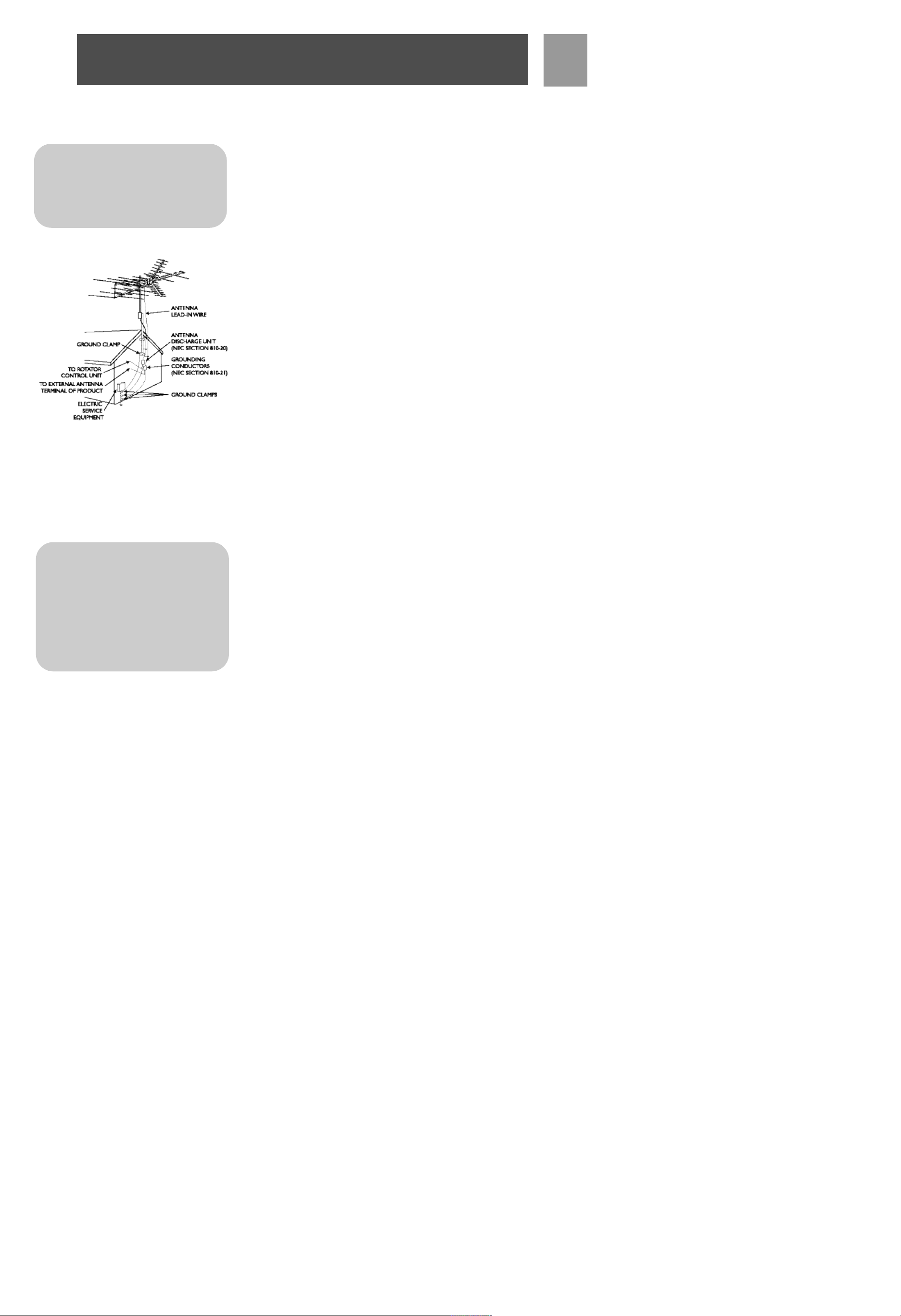
2 . Each conductor of a lead-in from an outdoor antenna should be
connected with an antenna discharge unit.Antenna discharge units
(or Lightning A rrestor) should be located outside the building or
inside the building between the point of entrance of the lead-in and
the T V, and as near as practical to the entrance of the conductors
to the building.
I m p o rtant Safety Notes
If you do not feel comfo rtable or competent to install this antenna we
recommend that you seek the assistance of a qualified pro fe s s i o n a l
antenna installer.
Read the instructions for this device thoro u g h ly befo re attempting
i n s t a l l a t i o n .
The installation or dismantling of any antenna near power lines is dang e ro u s . Each year hundreds of people are killed or injured while
attempting to install or service antennas. For your safety and pro p e r
antenna installation, read and fo l l ow all safety pre c a u t i o n s .
Choose an installation site for safety as well as perfo r m a n c e.
All electric power lines, cable lines and telephone lines look alike.To
be safe, assume ANY overhead line can kill yo u .
Do not place an antenna where it could potentially fall on to,or blow
into a power line. If in doubt call your electric prov i d e r. Let them
rev i ew your site.
Outdoor antennas should be grounded with an ap p r oved lighting arre s t ing dev i c e.Local codes may ap p l y. Use 8 AWG or larger ground wire.
Height or other restrictions on antennas may ap p ly to your installation depending on your proximity to an airport , or local ord i n a n c e s .
EN
Safety Instructions
I M P O RTA N T
READ
B E F O R E
I N S TA L L AT I O N
NEC - National Electrical Code
*Antenna Discharge Unit is not required if
lead in conductors are enclosed in a continuous metallic shield that is permanently
and effectively grounded.
Warning Installation of this product
near power lines is dangerous. For
your safety, keep ladder and antenna
away from power lines. Contact may
cause electrocution.
4
EN
Safety Instructions
Ta k e the time to plan your installation pro c e d u re. Do all assembly
work on the antenna on the gro u n d . Raise the completed antenna
after assembly.
Do NOT work on a we t , s n owy or windy day or if a thunderstorm is
ap p ro a c h i n g . Do NOT use a metal ladd e r.
If the antenna assembly starts to fall, get aw ay from it and let it fall.
Remember that the antenna mast and cable are all excellent conductors of electrical curre n t .
Do NOT install the antenna by yo u r s e l f . Be sure that there are two
other people available for help.
If any part of the antenna should come in contact with a power line .
. . DON'T TOUCH IT OR T RY TO REMOVE IT YO U R S E L F. Call yo u r
local power company immediately.T h ey will re m ove it.
Should an electrical accident occur .. .DON'T TOUCH THE PERSON
IN CONTACT WITH THE POWER LINE, or you too can become
e l e c t ro c u t e d . I n s t e a d , use a DRY board , s t i c k , or rope to push or pull
the victim aw ay from the power lines and antenna. Once clear, c h e c k
the victim. If he has stopped bre a t h i n g , i m m e d i a t e ly administer card i o p u l m o n a ry resuscitation (CPR) and stay with him. H ave someone
else call for medical help.
Install wire antennas high enough that they will not be "walked into"
by people.
Do not install antenna wire(s) over or under utility lines.
I M P O RTA N T
READ
B E F O R E
I N S TA L L AT I O N
5
EN
P a rts included:
a. UHF Boom-A . . . . . . . . . . . . . . . . . 2
b. UHF Boom-B . . . . . . . . . . . . . . . . . 2
c. VHF Boom-A . . . . . . . . . . . . . . . . . 1
d. VHF Boom-B . . . . . . . . . . . . . . . . . 2
e. Reflector Elements . . . . . . . . . . . . . 2
f. 46˝ Element . . . . . . . . . . . . . . . . . . 2
g. 50˝ Element . . . . . . . . . . . . . . . . . . 2
h. Tubing Brace . . . . . . . . . . . . . . . . . . 2
j. Phasing Wire . . . . . . . . . . . . . . . . . . 2
k. Reflector Brackets . . . . . . . . . . . . . 2
l. Pivot Brackets . . . . . . . . . . . . . . . 4
n. Locking Brackets . . . . . . . . . . . . . . . 4
p. End Caps . . . . . . . . . . . . . . . . . . . . . 8
q. Screws (1-3/4˝) . . . . . . . . . . . . . . . . 5
r. Screws (1-1/2˝) . . . . . . . . . . . . . . . 10
s. Screws (3/4˝) . . . . . . . . . . . . . . . . . 2
t. Lock Washers/ Washers . . . . . . . 6, 4
u. Wing-Nuts . . . . . . . . . . . . . . . . . . 17
v. Nuts . . . . . . . . . . . . . . . . . . . . . . . . 6
w. Band Separator . . . . . . . . . . . . . . . . 1
x. U-Bolt . . . . . . . . . . . . . . . . . . . . . . . 3
y. Cross Piece (for U-Bolt Assembly) 3
z. Antenna Saddle . . . . . . . . . . . . . . . . 1
*Quantities listed include those which may already be attached to antenna
NOTE: Cable, mast and mounting brackets are not included.
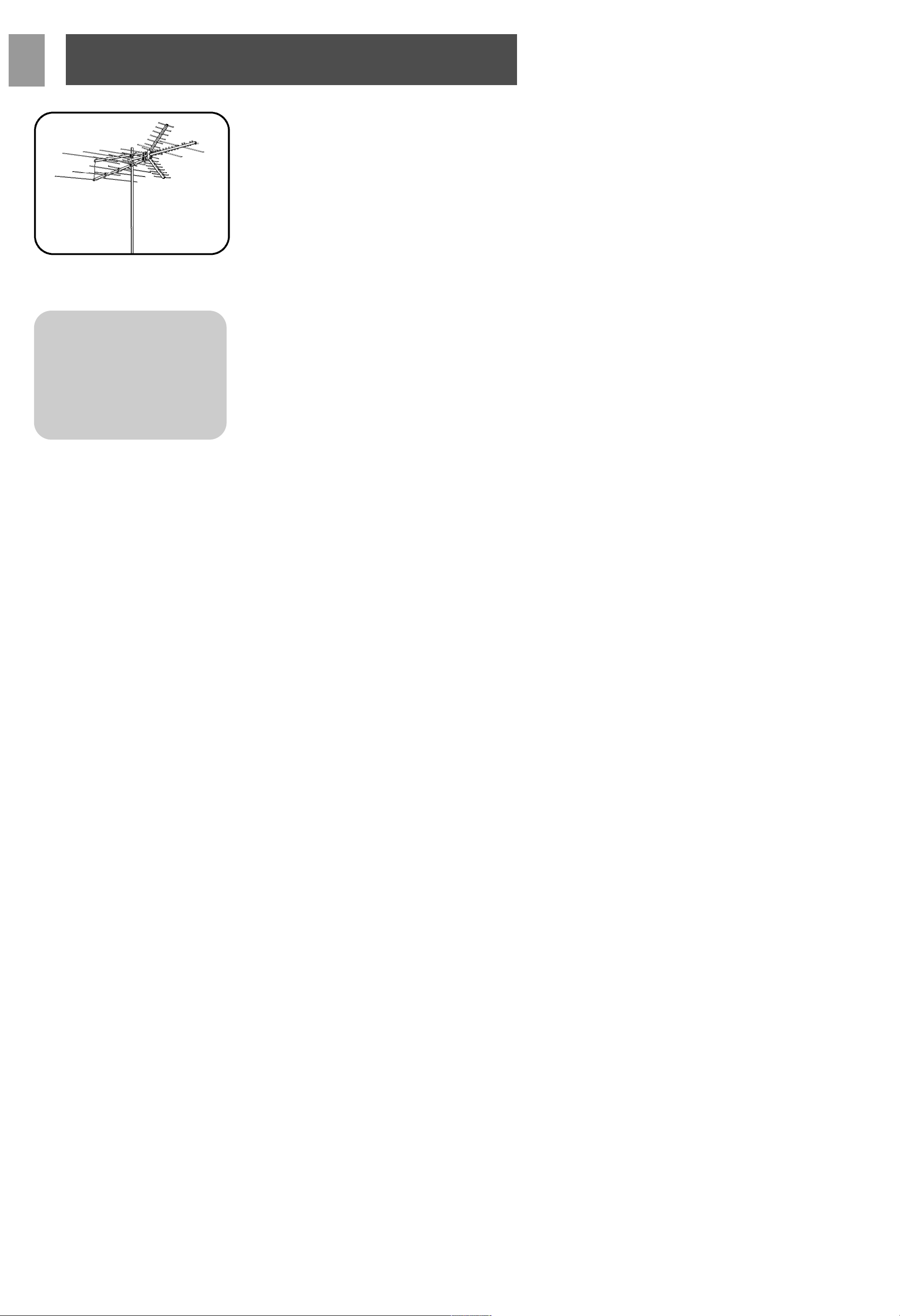
Assembly of UHF Portion
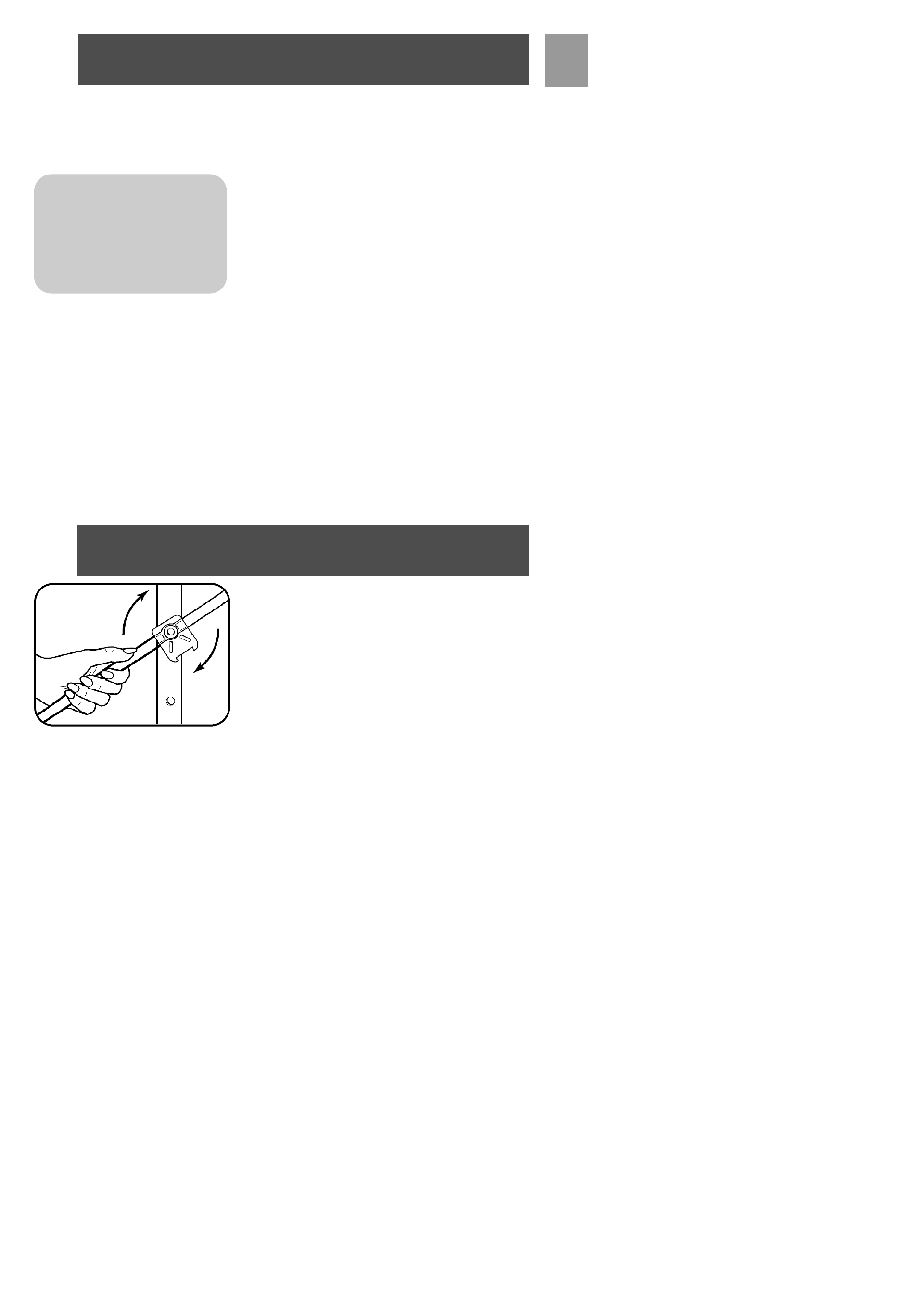
• Rotate reflector element rods into place. NOTE: When
rotating element rods, grasp close to pivot and relieve spring
pressure on pivot bracket detents. Don’t apply excess pressure to reflector element rods.
Included with Antenna
Assembly
N o t e : For final installation and
connection of your antenna, a dd i tional hard w a re may be re q u i re d .
B e fo re starting assembly, p l e a s e
read through the instructions caref u l l y to determine your specific
re q u i re m e n t s .
6
EN
Assembly
• Insert UHF Boom-A into UHF Boom-B and secure using
1-1/2˝ screw and lock washer.
• Attach Reflector Arm Mounting Brackets to assembled UHF
Boom (previous step) using two 1-1/2˝ screws and wing-nuts.
Ensure that rotation arcs in Reflector Arm Mounting Brackets
face toward UHF Boom elements.
• Attach Corner Reflector Arms to Reflector Arm Mounting
Brackets by sliding Reflector Arms between Mounting
Brackets. Secure with 1-1/2˝ screw and wing-nuts. To fully
secure Reflector Arms, snap into locking tabs and tighten
screws.
Assembly of VHF Portion
• Rotate reflector element rods on VHF Boom-A and VHF
Boom-B into place. NOTE: When rotating element rods,
grasp close to pivot and relieve spring pressure on pivot
bracket detents. Don’t apply excess pressure to reflector element rods.
• Attach one 46˝ Element to hole A in VHF Boom-B.
• Attach one 50˝ Element to VHF Boom-B.
Repeat each steps with second boom for VHF Boom-B.
7
EN
Assembly
• InsertVHF Boom-B into VHF Boom-A and secure using 1-1/2˝
screw and lock washers. Repeat steps for 2nd boom as well.
• Attach tubing brace to rear of VHF Boom with 1-1/2˝ screws
and wing-nuts.
• Slide UHF Boom through center slot of VHF Boom support
block until hole A of UHF Boom aligns with hole B of VHF
Boom. Secure with 1-1/2˝ screw and wing-nut.
• Attach phasing wire and lead-in wire to UHF antenna using
3/4˝ screws, washers, and wing-nuts.
• Insert end caps at ends of all booms.
Mast Assembly (Mast not included)
• Assemble U-bolts to cross pieces.
• Use saddle on center of boom.
• Assemble U-bolt assemblies loosely to antenna.
• Insert mast through U-bolts.
• Tighten U-bolts securely. All U-bolts should be on one side
of mast.
• Attach mast standoff to mast.
• Insert wire in standoff and tighten with pliers.
• Power lines should be as far away as possible.
• Assemble U-bolts in wall mounts with lock washers and nuts.
• Secure mounts to wall with wood screws.
• Separate mounts by at least two feet.
• Insert mast with assembled antenna through both U-bolts.
• Face antenna toward TV station.
• Tighten U-bolts securely.
• Wall mounts and chimney mounts are not included.
8
EN
Assembly
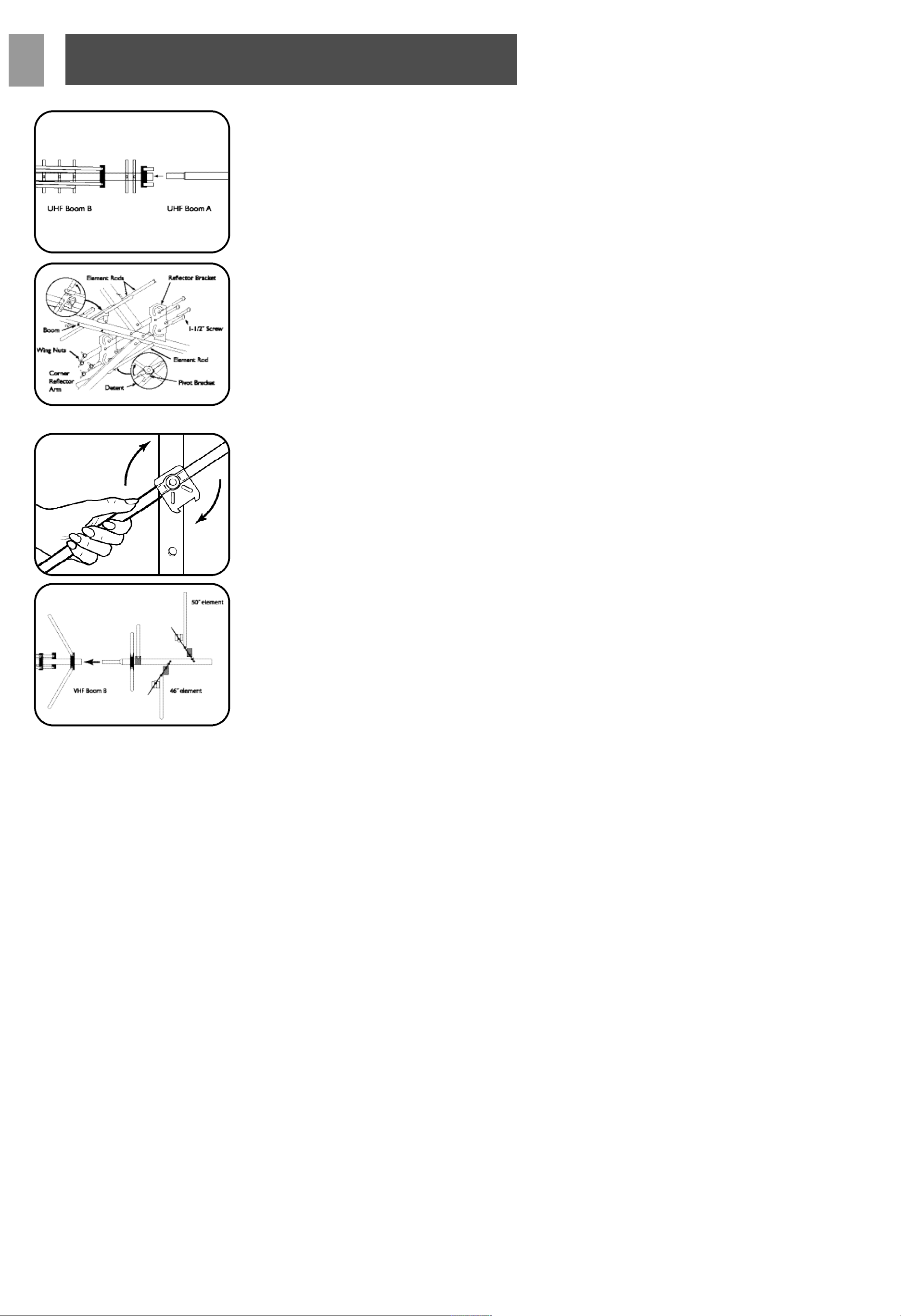
Lead-In Wire
• Attach lead-in wire to house with screw-type standoffs.
• Tighten standoffs with pliers after wire is installed.
• Avoid sharp bends in lead-in wire.
• Form drip loop where wire enters wall.
• Wall mounts not included.
• Mounts, mast and standoffs are not included.
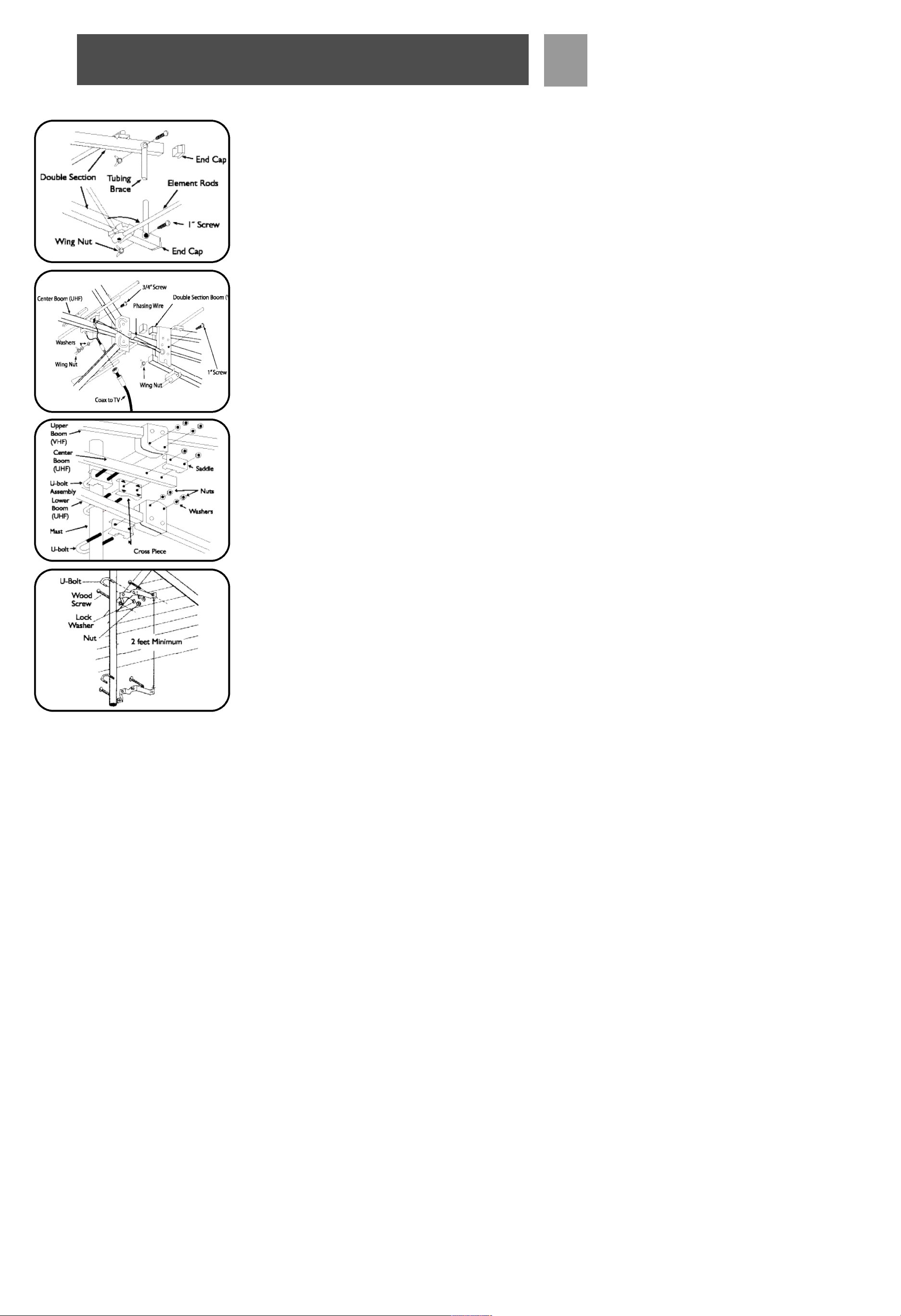
Band Separator
• Attach band separator to appropriate terminals on TV set.
• Attach antenna lead-in wire to band separator.
• An FM set or second TV set may be attached to second output
of band separator.
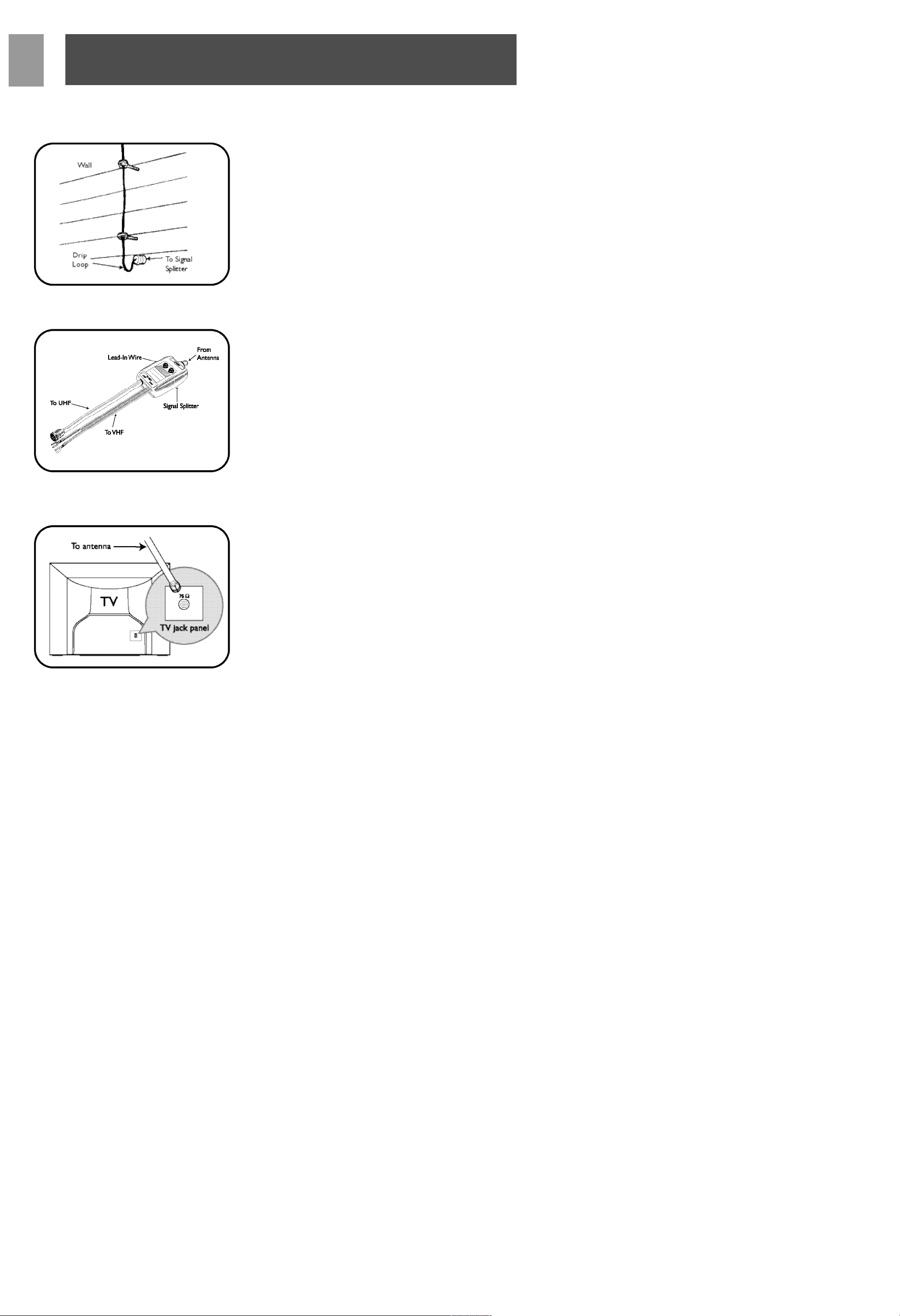
NOTE: Band separator is only required for older TV sets with separate VHF/UHF inputs. For most newer sets, simply connect cable
from antenna to ‘F’ input.

9
SP
Warranty
Limited Lifetime Warranty
The manufacturer warrants that this product shall be free from
defects in material,workmanship and assembly,under normal use, in
accordance with the specifications and warnings, for as long as you
own this product. This warranty extends only to the original purchaser of the product, and is not transferable. Defective products,
together with the dated proof of purchase, must be returned to the
place of purchase for repair or replacement. THERE ARE NO
OTHER EXPRESS WARRANTIES. Incidental and consequential
damages are disclaimed where permitted by law. This warranty gives
you specific legal rights, and you may also have other rights which
vary from state to state.
Technical Support
For Technical support send an email with the model number of the
product and a detailed description of your problem to:
Email: tech.support@philips.com
©2006
Accessories Service Center
Philips
Accessories and Computer Peripherals,
Ledgewood, NJ 07852 USA
Quality assured in USA
Printed in China
Technical Support
 Loading...