

Page 1
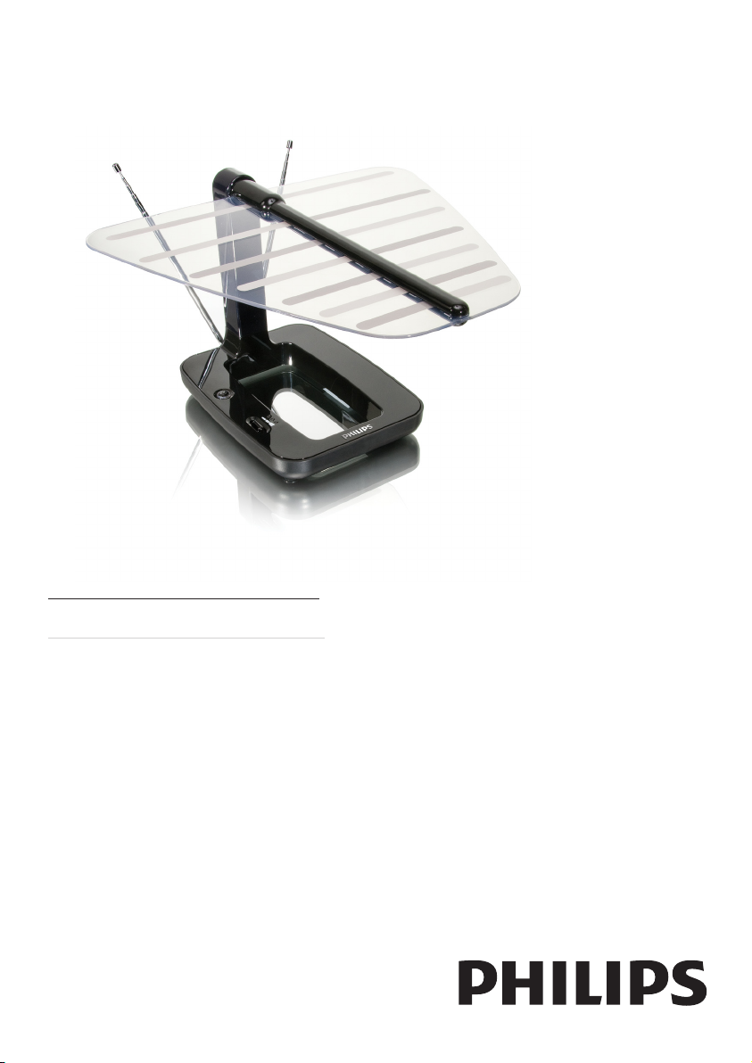
Register your product and get support at
www.philips.com/welcome
SDV7120/10
EN User manual
Page 2

Page 3

Contents
1 Important 4
Safety 4
Recycling 4
2 Your SDV7120 5
Overview 5
3 Get started 6
Installation 6
4 Set up SDV7120 7
For VHF/FM reception 7
For UHF reception 7
Set up a digital tuner with this antenna 8
5 Frequently asked questions 9
6 Warranty and service 9
English
7 Glossary 10
EN
3
Page 4
1 Important
Safety
This manual contains important information
about the Philips indoor television antenna.
Read it carefully before you start the installation
and setup.
Recycling
Your product is designed and manufactured
with high quality materials and components,
which can be recycled and reused.
When you see the crossed-out wheel bin
symbol attached to a product, it means the
product is covered by the European Directive
2002/96/EC:
When this logo is attached to a product, it
means a nancial contribution has been paid to
the associated national recovery and recycling
system.
© 2008 Koninklijke Philips Electronics N.V. All
rights reserved. Reproduction in whole or in
part is prohibited without the written consent
of the copyright owner. Trademarks are the
property of Koninklijke Philips Electronics N.V.
or their respective owners.
Never dispose of your product with other
household waste. Please inform yourself about
the local rules on the separate collection of
electrical and electronic products. The correct
disposal of your old product helps prevent
potentially negative consequences on the
environment and human health.
4 EN
Page 5
2 Your SDV7120
9
2
3
4
6
8
Congratulations on your purchase and welcome
to Philips!
To fully benet from the suppor t that Philips
offers, register your product at www.philips.
com/welcome.
Overview
English
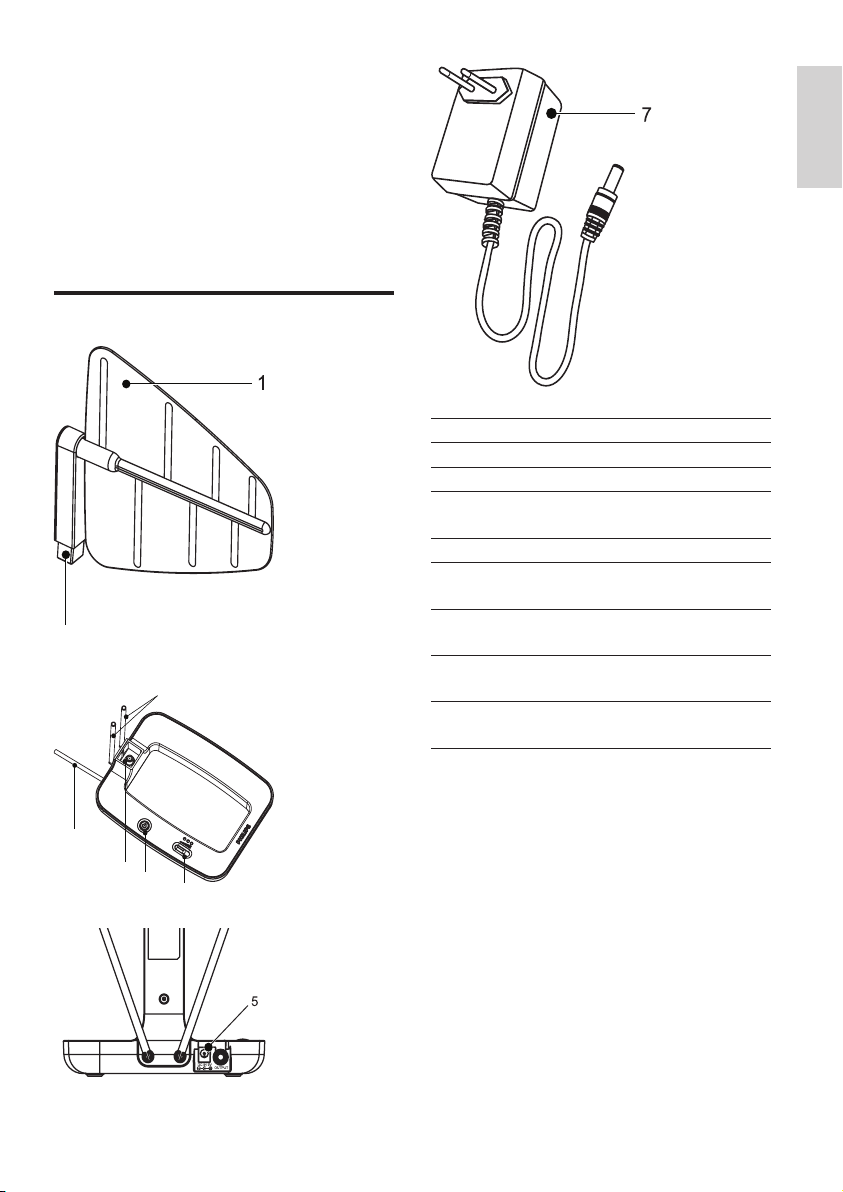
1 UHF log periodic antenna
2 VHF rod antenna
3 UHF/VHF gain control switch
4 Power switch with LED
indicator
5 9V DC power connection
6 Coaxial cable (for TV
connection)
7 230-240V AC/9V DC power
adaptor (included)
8 Antenna base with female
connector
9 UHF log periodic antenna
with male connector
5
EN
Page 6
3 Get started
To ensure the antenna to work properly, read
the user manual of your television before you
start. Set the television so that it receives the
signal from an ANTENNA instead of CABLE or
SATELLITE.
Installation
Determine the signal strength
Before Installation, determine the best location
for optimum reception. It is impor tant for the
antenna to have an unobstructed path to the
transmitter. For best results, ensure the antenna
faces the location of the transmitter.
Note
Choose a location near a window which gives the •
antenna a clear view of the transmitter.
Note
Place the antenna away from the metal surface to •
avoid interference.
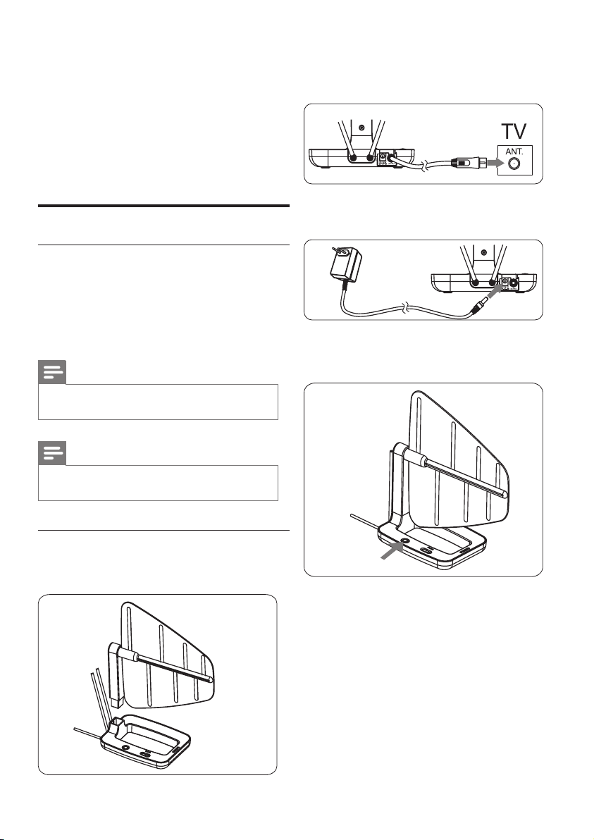
2 Connect the other end of the built-in
coaxial cable to the input on the TV
receiver.
3 Connect the DC plug to the antenna and
the power supply to a 230V AC outlet.
4 Turn the power switch on.
The blue LED is lit. »
Connect to the TV
1 Assemble the antenna base to the UHF log
periodic antenna.
6 EN
Page 7
4 Set up SDV7120
For VHF/FM reception
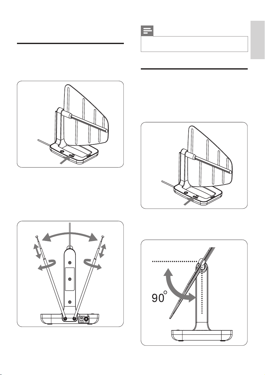
To turn the amplier up, switch the gain
1
control towards the max level.
2 Extend the VHF rod antenna to the
longest possible length.
3 Turn the TV or FM radio to the desired
channel/station. Move the VHF rod
antenna in different directions up and
down until the reception is achieved.
Note
It is possible to switch the gain control level down for •
best reception.
For UHF reception
Turn the TV to the desired channel/
1
station.
2 To turn the amplier up, switch the gain
control towards the max level.
3 Tilt or swivel the UHF log periodic
antenna towards the transmitter until the
reception is achieved.
English
EN
7
Page 8

Note
It is possible to switch the gain control level down for •
best reception.
Note
The UHF log periodic element only allows 90 •
degrees rotation.
Set up a digital tuner with this antenna
You can install available channels with the digital
TV tuner. This automatic process is part of the
setup of the tuner. Ensure the antenna has
set up properly before the tuner can receive
viewable channels.
There are two ways to connect the antenna to
the TV:
Connect the antenna to a digital tuner. •
If the signal strength is good enough, the
channels can be memorized in the tuner
automatically .
Connect the antenna directly to the TV. •
Tune to the analogue channels and nd the
best antenna location. Then re-connect
the antenna to the digital tuner. Ensure the
signal strength is good enough before you
install the channels with the tuner.
8 EN
Page 9
5 Frequently
6 Warranty and
asked questions
Can this antenna work with Analogue
transmissions?
Yes, this antenna can receive analogue
television broadcasts in the UHF and VHF
bandwidths.
Can this antenna receive digital or work with
HD-DVB broadcasts?
Yes, this antenna is designed to receive digital
DVB and HDTV broadcasts in the UHF &
VHF bandwidths.
Can the antenna be powered by a DC power
supply in a boat, RV or camper?
Yes, there is a DC power socket located at the
back of the antenna. Plug your cable/adapter into
the antenna and then into your power source.
Where should I place the antenna in order to
get the best reception possible?
Choose a location near a window which gives
the antenna a clear view of the transmitter.
Note
For bes t reception , place the antenna away from the •
metal surface to avoid interference .
service
Warranty information can be found at: www.
philips.com/welcome
For technical support, send us an email
with the model number of the product
and a detailed description of your problem
to:accessorysuppor [email protected]
English
How do I know how much gain (amplication)
is required to receive a clear picture?
Once you have the VHF dipoles ex tended to the
longest length, turn on the amplier. Turn the
amplier up to the max position and then reduce
as needed. In some case, you need to turn the
amplier down to receive a clearer picture.
Can I set up this antenna with a digital tuner?
Yes, this antenna can be set up with a digital
tuner. (see ‘Set up a digital tuner with this
antenna’ on page 9)
EN
9
Page 10

7 Glossary
A
Amplier
A device, either a single stage or a large scale
circuit with multiple stages for creating gain,
i.e. it makes small signals larger.
Antenna
A device, such as a rod or wire, which picks up
a received radio frequency signal or radiates a
transmitted RF signal.
C
Coaxial
A single copper conductor, surrounded with
a layer of insulation, covered by a surrounding
copper shield and nally, an insulating jacket.
An unbalanced transmission line with constant
impedance. In audio, this type is commonly
used for low level, line signals terminated in
RCA connectors.
F
Female connector
A female connector is a connector attached
to a wire, cable, or piece of hardware, having
one or more recessed holes with electrical
terminals inside, and constructed in such a
way that a plug with exposed conductors
(male connector ) can be inser ted snugly into
it to ensure a reliable physical and electrical
connection.
FM (Frequency Modulation)
In radio broadcasting: a method of modulation
in which the frequency of the carrier voltage
is varied with the frequency of the modulation
voltage.
H
HDTV (High-Denition Television)
It is a digital television broadcasting system
with higher resolution than traditional
television systems (standard-denition TV,
or SDTV ). HDTV is digitally broadcast;
the earliest implementations used analog
broadcasting, but today digital television
(DTV) signals are used, requiring less
bandwidth due to digital video compression.
M
Male connector
A male connector is a connector attached
to a wire, cable, or piece of hardware, having
one or more exposed, unshielded electrical
terminals, and constructed in such a way that
it can be inser ted snugly into a receptacle
(female connector) to ensure a reliable
physical and electrical connection .
U
UHF (Ultra high frequency)
In radio or TV broadcasting: it is the frequency
range of electromagnetic waves which lies
between 300 MHz and 3 GHz (3000 MHz).
V
VHF (Very high frequency)
In radio or TV broadcasting: it is the frequency
range of electromagnetic waves which lies
between 30 MHz and 300 MHz.
10 EN
Page 11

Page 12

© 2008 Koninklijke Philips Electronics N.V.
All rights reserved. PDCC-PENG-0908
 Loading...